Sélection de la langue

Search

Sommaire du brevet 2374427 

Énoncé de désistement de responsabilité concernant l'information provenant de tiers

Une partie des informations de ce site Web a été fournie par des sources externes. Le gouvernement du Canada n'assume aucune responsabilité concernant la précision, l'actualité ou la fiabilité des informations fournies par les sources externes. Les utilisateurs qui désirent employer cette information devraient consulter directement la source des informations. Le contenu fourni par les sources externes n'est pas assujetti aux exigences sur les langues officielles, la protection des renseignements personnels et l'accessibilité.

Disponibilité de l'Abrégé et des Revendications

L'apparition de différences dans le texte et l'image des Revendications et de l'Abrégé dépend du moment auquel le document est publié. Les textes des Revendications et de l'Abrégé sont affichés :

  • lorsque la demande peut être examinée par le public;
  • lorsque le brevet est émis (délivrance).
(12) Brevet: (11) CA 2374427
(54) Titre français: DISPOSITIF DE FIXATION POUR AUTOPERCAGE
(54) Titre anglais: SELF-PUNCHING FASTENER
Statut: Périmé
Données bibliographiques
(51) Classification internationale des brevets (CIB):
  • F16B 37/00 (2006.01)
  • B23P 19/06 (2006.01)
  • F16B 37/06 (2006.01)
(72) Inventeurs :
  • ROSS, GEROLD (Allemagne)
  • LUDWIG, DETLEF (Allemagne)
(73) Titulaires :
  • NEDSCHROEF SCHROZBERG GMBH (Allemagne)
(71) Demandeurs :
  • TEXTRON VERBINDUNGSTECHNIK GMBH & CO. OHG (Allemagne)
(74) Agent: KIRBY EADES GALE BAKER
(74) Co-agent:
(45) Délivré: 2010-11-30
(22) Date de dépôt: 2002-03-04
(41) Mise à la disponibilité du public: 2003-02-22
Requête d'examen: 2006-04-10
Licence disponible: S.O.
(25) Langue des documents déposés: Anglais

Traité de coopération en matière de brevets (PCT): Non

(30) Données de priorité de la demande:
Numéro de la demande Pays / territoire Date
201 13 853.0 Allemagne 2001-08-22

Abrégés

Abrégé français

Attache auto-emboutissante à enfoncer dans un élément de feuille métallique de façon à empêcher la rotation ou le détachement. L'attache est constituée d'un corps annulaire dont l'un des côtés fait face à la feuille métallique et comporte des projections disposées en rayons. Les projections s'enfoncent dans la feuille métallique pendant l'emboutissage de façon à arrimer l'attache. Le centre de l'attache est fileté à l'intérieur. Le côté du corps annulaire comprend une cavité annulaire faisant face à la feuille métallique. Une partie du matériau est poussée dans la cavité annulaire pendant l'opération.


Abrégé anglais


A self-punching fastener can be pressed into a metal
sheet member in a way that prevents against rotation and
pressing out. The fastener has an annular body with a
side facing the metal sheet having radially disposed
projections. The projections are pressed into the metal
sheet member during the pressing-in and thereby secures
the fastener against rotation. An interior thread is
positioned in the center of fastener. An annular
depression is provided on the side of the annular body
facing the metal sheet member. Material is displaced
into the annular depression during the setting.

Revendications

Note : Les revendications sont présentées dans la langue officielle dans laquelle elles ont été soumises.


6

CLAIMS


1. Self-punching fastener for pressing into a metal
sheet in a manner that is safe from rotation and
pressing-out, the fastener comprising:

an annular body, having radially positioned
projections on a side thereof facing the metal sheet, the
projections being pressed into the metal sheet during
pressing and thereby securing the fastener against
rotation;

an interior thread in a center of the annular body;
and
the annular body having an annular depression on the
side facing the metal sheet, the projections being evenly
distributed in the annular depression;
the depression having a punching collar at an inner
limitation and a collar at an exterior limitation, the
projections being positioned at the collar at the
exterior limitation, the collar at the exterior
limitation having an undercut facing the annular
depression to receive material of the metal sheet for
locking against an axial pressing-out;
the punching collar limiting the annular depression
on the side of the annular body facing the metal sheet in
the direction of the interior thread such that the
punching collar punches a hole of a diameter of the
punching collar into the metal sheet during setting of
the fastener, the punching collar having an undercut
facing the annular depression in which material from the
metal sheet is received during pressing-in to provide a
further locking of the fastener against an axial
pressing-out, the annular depression being free of
projections adjacent the punching collar.


7

2. The fastener according to claim 1, wherein the
punching collar is adapted to a gauge of the metal sheet
with respect to a height of the metal sheet.


3. The fastener according to any one of the claims 1
or 2, wherein a bottom face of the annular depression is
inclined from an interior to an exterior in a direction
of the metal sheet.

Description

Note : Les descriptions sont présentées dans la langue officielle dans laquelle elles ont été soumises.


CA 02374427 2009-06-02

1
SELF-PUNCHING FASTENER
FIELD OF THE INVENTION

The present invention relates to a self-punching fastener
for pressing into a metal sheet in a manner that is safe
from rotation and pressing out.

BACKGROUND OF THE INVENTION

It is the task of the present invention to improve a
fastener so that a maximal range of gauges of the metal
sheet can be used without changing geometry of the

fastener and still providing a high safety against
rotation and pressing out without requiring a previous
punching or a special preparation of the holes into which
the fastener is to be set.

According to the prior art, known solutions were based on
the assumption that an optimal safety against rotation
and pressing out and a broad range of use of the fastener
is achieved if continuous ridges are provided within the
annular depression for locking against rotation and the
bottom of the annular depression is parallel to the
surface of the metal sheets.


CA 02374427 2009-06-02

2
SUMMARY OF THE INVENTION

The present invention is based on achieving an optimal
safety against rotation using burl-shaped locking
elements in a maximal distance to a central axis to make

use of the most effective lever against the rotational
momentum at the utmost supporting collar of an annular
depression.

By the above described displacing of the security against
rotation and the inclined formation of the bottom of the
annular depression at the innermost limit of the annular
depression - the punching collar - there is more space
available for the penetration of the cutting ring of the
punching die. This means it is possible to work with
larger thicknesses of the metal sheets or larger gauge

ranges with the solution according to the invention.
The coordination between the punching die geometry and
the shape of the annular depression and the security
against rotation according to the invention ensures that,
after the pressing-in of the metal sheet, jamming on the

punching die is prevented providing a high working
safety.

Material from the metal sheet is shaped into undercuts
formed during the production of parts and at the inner
punching collar as on the supporting collar of the

annular depression during the pressing-in. This ensures
that even when working with thin metal sheets, a high
safety against rotation and pressing out of the fastener
is achieved.


CA 02374427 2009-06-02

3
The shape of the projections or burls can be arched as
well as with sharp edges (triangular).

BRIEF DESCRIPTION OF THE DRAWINGS

In the following, the invention is more detailly
described with reference to the attached drawings.

Fig. 1 is a side elevation view of a fastener according
to the present invention;

Fig. 2 is a bottom plan view of the fastener of Fig. 1;
Fig. 3 is a bottom plan view of another embodiment of the
fastener;

Fig. 4 is a side elevation view of the fastener of Fig. 1
and a punching die in an open configuration;

Fig. 5 is a side elevation view of the fastener of Fig. 1
and the punching die in a closed configuration; and

Fig. 6 is a side elevation view of the fastener of Fig. 1
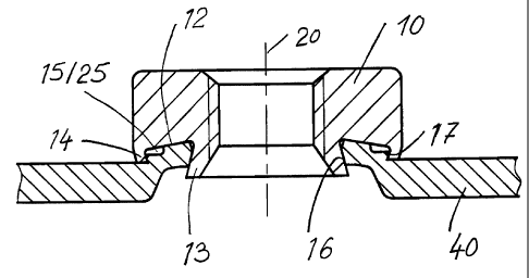
set in a metal sheet member.

DETAILED DESCRIPTION

Fig. 1 shows a fastener according to the invention in the
shape of a nut consisting of an annular basic body 10.

In a center of the cylindrical fastener 10 there is a
throughbore on which is formed a thread 11 over at least
a part of the height of the fastener 10.


CA 02374427 2009-06-02

4
On the bottom side, the fastener 10 has an annular
depression 12. The bottom face of the annular
depression 12 starts from an inner limitation, the
punching collar 13 and is inclined to an outer

limitation, the supporting collar 14. Within this
annular depression 12 there are evenly distributed
burl-shaped locking elements 15 in an annular array at
the supporting collar 14. The punching collar 13 has an
undercut 16 towards an axis 20 of the fastener 10. The
supporting collar 14 has an undercut 17 in the direction
of an exterior enveloping face 18 of the fastener 10.
The punching collar 13 has a cutting edge 19.

Fig. 2 shows the fastener 10 of Fig. 1 in a bottom view.
The shape and the position of the burl-shaped locking
elements 15 are clearly shown. The burl-shaped locking

elements 15 are positioned at the outer supporting
collar 14 and form a free-space towards the punching
collar 13. In this representation (Fig. 2) the variant
with annularly shaped burl-shaped locking elements 15 is
shown.

Fig. 3 shows the fastener 10 in an embodiment having
sharp-edge (triangular) burl-shaped locking elements 25.
Fig. 4 shows the fastener 10 in accordance to Figs. 1, 2
and 3 as well as a punching die 30 and a metal sheet 40.
From this representation it can be seen that the metal
sheet 40 does not have a prefabricated hole and does not
need any further preparation. The punching die 30 has a
cutting edge 31 and a swaging ring 32 having a special
geometry 33. An exterior enveloping face 34 of the
swaging ring 32 runs conically towards the central


CA 02374427 2009-06-02

axis 20 of the punching die 30. This ensures that after
the punching and pressing-in of the metal sheet 40 into
the annular depression 12, jamming of the swaging ring 32
in the metal sheet 40 is avoided.

5 Fig. 5 shows the fastener 10 of Figs. 1 to 3 shortly
after the finalization of the setting procedure. The
punching collar 13, in cooperation with the cutting edge
31 of

the punching die 30, punches a disk 41 from the metal
sheet 40. The material of the metal sheet 40 is swaged
into the annular depression 12 by the swaging ring 32
enclosing the burl-shaped locking elements 15, 25. The
stemmed out disk 41 is discarded downwardly from the
punching die 30.

Fig. 6 shows the fastener 10 completely set in a metal
sheet 40. The action of the undercut 16, 17 at the
punching collar 13 and at the supporting collar 14 is
clearly shown. The annular depression 12 is filled with
the material of the metal sheet 40. The burl-shaped
locking elements 14, 25 are embedded in the metal
sheet 40. The positive action of the bottom face of the
annular depression 12 inclined to the exterior for
enlarging the active length of the punching collar 13 and
therefore for increasing the range of useable gauge

ranges of the metal sheets for the fastener 10 according
to the invention can be clearly noticed.

Dessin représentatif
Une figure unique qui représente un dessin illustrant l'invention.
États administratifs

Pour une meilleure compréhension de l'état de la demande ou brevet qui figure sur cette page, la rubrique Mise en garde , et les descriptions de Brevet , États administratifs , Taxes périodiques et Historique des paiements devraient être consultées.

États administratifs

Titre Date
Date de délivrance prévu 2010-11-30
(22) Dépôt 2002-03-04
(41) Mise à la disponibilité du public 2003-02-22
Requête d'examen 2006-04-10
(45) Délivré 2010-11-30
Expiré 2022-03-04

Historique d'abandonnement

Il n'y a pas d'historique d'abandonnement

Historique des paiements

Type de taxes Anniversaire Échéance Montant payé Date payée
Enregistrement de documents 100,00 $ 2002-03-04
Le dépôt d'une demande de brevet 300,00 $ 2002-03-04
Taxe de maintien en état - Demande - nouvelle loi 2 2004-03-04 100,00 $ 2004-02-18
Taxe de maintien en état - Demande - nouvelle loi 3 2005-03-04 100,00 $ 2005-02-18
Taxe de maintien en état - Demande - nouvelle loi 4 2006-03-06 100,00 $ 2006-01-31
Requête d'examen 800,00 $ 2006-04-10
Taxe de maintien en état - Demande - nouvelle loi 5 2007-03-05 200,00 $ 2007-01-31
Taxe de maintien en état - Demande - nouvelle loi 6 2008-03-04 200,00 $ 2008-02-05
Enregistrement de documents 100,00 $ 2008-05-26
Taxe de maintien en état - Demande - nouvelle loi 7 2009-03-04 200,00 $ 2009-02-04
Taxe de maintien en état - Demande - nouvelle loi 8 2010-03-04 200,00 $ 2010-02-16
Taxe finale 300,00 $ 2010-09-15
Taxe de maintien en état - brevet - nouvelle loi 9 2011-03-04 200,00 $ 2011-01-19
Taxe de maintien en état - brevet - nouvelle loi 10 2012-03-05 450,00 $ 2012-03-29
Taxe de maintien en état - brevet - nouvelle loi 11 2013-03-04 250,00 $ 2013-01-28
Taxe de maintien en état - brevet - nouvelle loi 12 2014-03-04 450,00 $ 2014-07-10
Taxe de maintien en état - brevet - nouvelle loi 13 2015-03-04 450,00 $ 2016-02-25
Taxe de maintien en état - brevet - nouvelle loi 14 2016-03-04 250,00 $ 2016-02-25
Taxe de maintien en état - brevet - nouvelle loi 15 2017-03-06 450,00 $ 2017-01-25
Enregistrement de documents 100,00 $ 2017-07-28
Taxe de maintien en état - brevet - nouvelle loi 16 2018-03-05 650,00 $ 2018-03-22
Taxe de maintien en état - brevet - nouvelle loi 17 2019-03-04 650,00 $ 2019-03-20
Taxe de maintien en état - brevet - nouvelle loi 18 2020-03-04 450,00 $ 2020-02-20
Titulaires au dossier

Les titulaires actuels et antérieures au dossier sont affichés en ordre alphabétique.

Titulaires actuels au dossier
NEDSCHROEF SCHROZBERG GMBH
Titulaires antérieures au dossier
ACUMENT GMBH & CO. OHG
LUDWIG, DETLEF
ROSS, GEROLD
RT HOLDINGS III WG (US), LP SCS
RUIA GLOBAL FASTENERS AG
TEXTRON VERBINDUNGSTECHNIK GMBH & CO. OHG
WHITESELL GERMANY GMBH & CO. KG
Les propriétaires antérieurs qui ne figurent pas dans la liste des « Propriétaires au dossier » apparaîtront dans d'autres documents au dossier.
Documents

Pour visionner les fichiers sélectionnés, entrer le code reCAPTCHA :


Pour visualiser une image, cliquer sur un lien dans la colonne description du document. Pour télécharger l'image (les images), cliquer l'une ou plusieurs cases à cocher dans la première colonne et ensuite cliquer sur le bouton "Télécharger sélection en format PDF (archive Zip)" ou le bouton "Télécharger sélection (en un fichier PDF fusionné)".

Liste des documents de brevet publiés et non publiés sur la BDBC .

Si vous avez des difficultés à accéder au contenu, veuillez communiquer avec le Centre de services à la clientèle au 1-866-997-1936, ou envoyer un courriel au Centre de service à la clientèle de l'OPIC.


Description du
Document 
Date
(yyyy-mm-dd) 
Nombre de pages   Taille de l'image (Ko) 
Description 2002-03-04 4 182
Revendications 2002-03-04 2 63
Description 2009-06-02 5 157
Abrégé 2009-06-02 1 16
Revendications 2009-06-02 2 46
Dessins 2002-03-04 3 63
Dessins représentatifs 2002-06-03 1 8
Page couverture 2003-01-27 1 39
Abrégé 2002-03-04 1 20
Page couverture 2010-11-08 1 37
Revendications 2010-04-14 2 48
Dessins représentatifs 2010-11-08 1 9
Poursuite-Amendment 2006-04-10 1 33
Cession 2002-03-04 4 127
Correspondance 2010-09-15 1 36
Cession 2008-05-26 6 208
Cession 2008-09-17 8 224
Poursuite-Amendment 2009-03-17 4 154
Poursuite-Amendment 2009-06-02 11 306
Poursuite-Amendment 2009-11-18 2 52
Poursuite-Amendment 2010-04-14 4 107
Taxes 2012-03-29 1 163
Correspondance 2012-03-29 1 89
Taxes 2014-07-10 1 33
Taxes 2016-02-25 1 33