Language selection

Search

Patent 2394601 Summary

Third-party information liability

Some of the information on this Web page has been provided by external sources. The Government of Canada is not responsible for the accuracy, reliability or currency of the information supplied by external sources. Users wishing to rely upon this information should consult directly with the source of the information. Content provided by external sources is not subject to official languages, privacy and accessibility requirements.

Claims and Abstract availability

Any discrepancies in the text and image of the Claims and Abstract are due to differing posting times. Text of the Claims and Abstract are posted:

  • At the time the application is open to public inspection;
  • At the time of issue of the patent (grant).
(12) Patent: (11) CA 2394601
(54) English Title: FEED ROLLER AND A METHOD FOR ASSEMBLING A FEED ROLLER
(54) French Title: ROULEAU D'ENTRAINEMENT ET PROCEDE D'ASSEMBLAGE D'UN ROULEAU D'ENTRAINEMENT
Status: Expired
Bibliographic Data
(51) International Patent Classification (IPC):
  • B27B 25/02 (2006.01)
(72) Inventors :
  • NILSSON, GUNNAR (Sweden)
(73) Owners :
  • PARTEK FOREST AB (Sweden)
(71) Applicants :
  • PARTEK FOREST AB (Sweden)
(74) Agent: SMART & BIGGAR IP AGENCY CO.
(74) Associate agent:
(45) Issued: 2008-07-08
(86) PCT Filing Date: 2000-12-08
(87) Open to Public Inspection: 2001-07-05
Examination requested: 2003-11-06
Availability of licence: N/A
(25) Language of filing: English

Patent Cooperation Treaty (PCT): Yes
(86) PCT Filing Number: PCT/SE2000/002471
(87) International Publication Number: WO2001/047672
(85) National Entry: 2002-06-17

(30) Application Priority Data:
Application No. Country/Territory Date
9904810-0 Sweden 1999-12-28

Abstracts

English Abstract


Feed roller in tree processing machinery for feeding
tree trunks through the machinery distinguished in that the
flange (2) is arranged essentially in the centre of the wheel rim
(1) and that a track (4) of elastic material is arranged on either
side of the flange (2). A ring (5) is arranged on the side of the
respective track (4) that is opposite the flange, whereby the rings
(5) that abut the outer sides of the elastic track on either side of the
wheel are joined with one another by means of tensioning devices
(8).


French Abstract

L'invention se rapporte à un rouleau d'entraînement mis en oeuvre dans une machine de traitement du bois et conçu pour amener des troncs d'arbres dans ladite machine. Ce rouleau d'entraînement se caractérise en ce qu'il comporte une bride (2) disposée sensiblement au centre de la jante (1) de roue et en ce qu'un tracé (4) de matière élastique est disposé de part et d'autre de la bride (2). Un anneau (5) est disposé sur le côté du tracé respectif (4) qui est opposé à la bride, ce qui permet aux anneaux (5) qui sont en aboutement avec les côtés externes du tracé élastique de part et d'autre de la roue de s'assembler au moyen de dispositifs de mise en tension (8).

Claims

Note: Claims are shown in the official language in which they were submitted.


3

CLAIMS:


1. Feed roller for tree-processing machinery for
feeding tree trunks through the machinery characterised in
that it comprises an essentially cylindrically-shaped wheel
rim (1) with a radially outwardly facing flange (2) located
essentially at the centre of the wheel rim (1), a pair of
tracks (4) of elastic material each arranged on the wheel
rim on opposite sides of the flange (2) such that they abut
the flange (2), plus a pair of rings (5) each arranged on
the side of each track (4) opposite to the flange (2) such
that they abut the track (4), wherein the pair of rings (5)
abutting the outside of the tracks (4) are joined by means
of a tensioning device (8).


2. The feed roller of claim 1 wherein the flange (2)
has a plurality of holes or recesses adapted to receive the
elastic material of the tracks (4).


3. The feed roller of claim 1 or 2 wherein the
tensioning device is a chain.


4. The feed roller of any one of claims 1 to 3 which
further comprises attachment means for attaching the
tensioning device (8) to the rings (5) which attachment
means comprise an end piece projecting outwardly from each
of the rings (5) which end piece is provided with a hole for
receiving securing means.


5. Procedure for fitting a feed roller to tree-
processing machinery for feeding tree trunks through the
machinery characterised in that a ring-shaped track (4) of
elastic material is pushed onto either side of a wheel rim
(1) provided with an outwardly facing flange (2) located
essentially at the centre of the wheel rim such that the
track (4) abuts the flange (2), a ring (5) is applied to the


4


side of the track (4) opposite the flange (2) and a
tensioning device (8) is brought between the ring (5) and
another part of the feed roller on the opposite side of the
ring (5).


6. The procedure of claim 5 wherein the flange (2)
further comprises a plurality of holes or recesses which
receive the elastic material of the tracks (4).


7. The procedure of claim 5 or 6 wherein the
tensioning device is a chain.


8. The procedure of any one of claims 5 to 7 wherein
the tensioning device (8) is attached to the ring (5) by
means of an end piece projecting outwardly from the ring (5)
which end piece is provided with a hole for receiving
securing means.


9. The procedure of any one of claims 5 to 8 wherein
the another part of the feed roller on the opposite side of
the ring comprises an additional ring.


Description

Note: Descriptions are shown in the official language in which they were submitted.


CA 02394601 2007-12-06
20368-724

1
Feed roller and a method for assembling a feed roller
The present invention relates to a feed roller

used in tree-processing machinery to feed the trunk of the
tree through the machinery.

Such feed rollers used in tree-processing machines
or tree harvesters are normally equipped with a vulcanised
tread of, for example, rubber, attached to a wheel rim and
surrounded by cross-running chain links or a net of chain
links to attain a better grip when feeding the tree trunks

forward. When the desired function of the feed roller no
longer exists, the roller must be dismounted and equipped
with a new tread. The costs for dismounting and fitting, as
well as for a new feed roller, are substantial.

The present invention seeks to eliminate the said
disadvantages of known feed rollers and provide these with a
longer life length and thus lower operating costs.

In accordance with the present invention there is
provided feed roller for tree-processing machinery for
feeding tree trunks through the machinery characterised in

that it comprises an essentially cylindrically-shaped wheel
rim with a radially outwardly facing flange located
essentially at the centre of the wheel rim, a pair of tracks
of elastic material each arranged on the wheel rim on
opposite sides of the flange such that they abut the flange,

plus a pair of rings each arranged on the side of each track
opposite to the flange such that they abut the track,
wherein the pair of rings abutting the outside of the

tracks are joined by means of a tensioning device.


CA 02394601 2007-12-06
20368-724

la
In a further aspect of the present invention there
is provided procedure for fitting a feed roller to tree-
processing machinery for feeding tree trunks through the
machinery characterised in that a ring-shaped track of

elastic material is pushed onto either side of a wheel rim
provided with an outwardly facing flange located essentially
at the centre of the wheel rim such that the track abuts the
flange, a ring is applied to the side of the track opposite
the flange and a tensioning device is brought between the
ring and another part of the feed roller on the opposite
side of the ring.

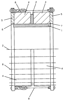
An example of the invention will be described in
greater detail with reference to the drawing where Figs. 1
and 2 show schematically as two different embodiments an

upper half of the roller as a cross-section through it and a
lower half of the roller seen across the direction of its
axis.

1 designates a cylindrical roller or hub in the
form of a wheel rim 1, made of steel, for example, that
radially along its periphery and in the centre of the rim
has an outwardly projecting flange 2 that is, for example,
permanently attached by welding to the wheel rim, see

Fig. 1. The roller 1 is supported in the traditional manner
so that it can be driven to rotate around an axle 3. A

circular-shaped track 4 of elastic material, for example
rubber, that runs around the wheel rim is arranged on each
side of the flange 2. Each track 4 is pushed onto the
cylindrical wheel rim 1 so that it abuts the flange 2. A
rigid ring 5, made of steel, for example, whose inner

periphery 6 has a radius that is greater than the outer
diameter of the wheel rim 1 is brought onto the outside of
the respective track 4. This is evident at 7. The rings 5
are joined with one another by means of a tensioning


CA 02394601 2007-12-06
20368-724

lb
device 8, here shown in the form of chains, that increases
the friction between the roller and the tree trunk and thus
reduces the risk for slippage.

The intention with the tensioning device 8 is also
to draw the rings towards one another and thereby press the
elastic tracks 4 between themselves and the flange 2. This
means that this change in shape due to the tension between
the rings 5 will press the tracks 4 against the periphery of
the wheel rim 1, against the flange 2 as well as against the

rings 5, which means that the tracks 4 will be prevented
from slipping or sliding in relation to the rim


CA 02394601 2002-06-17
WO 01/47672 PCT/SEOO/02471
2
1. To further ensure that slidi 1g or slipping cannot occur, the flange 2 can
be provided with a
number of recesses or holes t iat pass all the way through in which the
material of the tracks 4
will expand and lock the traclcs 4 to the flange 2.
In the example shown, it is suggested that the tensioning device is chains 8
that
can be tensioned between the rings 5 (the chains in the example shown are
indicated only by
dotted and dashed lines). The actual clamping of the respective chain at the
rings can naturally
take place in a number of ways that are obvious for a person skilled in the
art. In the figure, it
is suggested that the respective chain 8 is provided with an end piece that
has a part that
projects out from the respective ring 5 and that is provided with an elongated
hole for
accommodating, for example, a cotter, so that it can be locked at the ring to
secure its
function.
When, for example, the tracks 4 have been worn down to such a degree that the
function of the feed roller is no longer satisfactory, the chains 8 are
loosened and the rings 5
removed. The tracks 4 can now be easily drawn off from the hub of the roller
and replaced by
new tracks that are locked into place by means of the rings 5 and chains 8 as
described
previously. On many occasions, the tracks are worn down to a greater extent at
one of their
edges, in which case they can exchange places or be turned around before they
are pushed
back onto the hub of the roller.
One advantage that is obtained automatically with the invention is that
stretching of the tensioning device 8 is achieved when the tracks 4 are
fitted.
It should be realised that the invention can be designed in a number of
different
ways within the scope of the characteristics of claim 1. It can be considered,
for example, to
position the flange on one of the sides of the wheel rim and use only one
elastic track 4 and
ring 5, whereby the tensioning device 8 will extend between the ring 5
abutting the one side
of the track and the flange 2, see Fig. 2.

---------------

Representative Drawing
A single figure which represents the drawing illustrating the invention.
Administrative Status

For a clearer understanding of the status of the application/patent presented on this page, the site Disclaimer , as well as the definitions for Patent , Administrative Status , Maintenance Fee  and Payment History  should be consulted.

Administrative Status

Title Date
Forecasted Issue Date 2008-07-08
(86) PCT Filing Date 2000-12-08
(87) PCT Publication Date 2001-07-05
(85) National Entry 2002-06-17
Examination Requested 2003-11-06
(45) Issued 2008-07-08
Expired 2020-12-08

Abandonment History

There is no abandonment history.

Payment History

Fee Type Anniversary Year Due Date Amount Paid Paid Date
Application Fee $300.00 2002-06-17
Maintenance Fee - Application - New Act 2 2002-12-09 $100.00 2002-06-17
Registration of a document - section 124 $100.00 2002-10-01
Request for Examination $400.00 2003-11-06
Maintenance Fee - Application - New Act 3 2003-12-08 $100.00 2003-11-19
Maintenance Fee - Application - New Act 4 2004-12-08 $100.00 2004-11-10
Maintenance Fee - Application - New Act 5 2005-12-08 $200.00 2005-11-15
Maintenance Fee - Application - New Act 6 2006-12-08 $200.00 2006-11-14
Maintenance Fee - Application - New Act 7 2007-12-10 $200.00 2007-11-28
Final Fee $300.00 2008-04-24
Maintenance Fee - Patent - New Act 8 2008-12-08 $200.00 2008-11-24
Maintenance Fee - Patent - New Act 9 2009-12-08 $200.00 2009-11-09
Maintenance Fee - Patent - New Act 10 2010-12-08 $250.00 2010-11-08
Maintenance Fee - Patent - New Act 11 2011-12-08 $250.00 2011-11-23
Maintenance Fee - Patent - New Act 12 2012-12-10 $250.00 2012-11-30
Maintenance Fee - Patent - New Act 13 2013-12-09 $250.00 2013-11-18
Maintenance Fee - Patent - New Act 14 2014-12-08 $250.00 2014-11-26
Maintenance Fee - Patent - New Act 15 2015-12-08 $450.00 2015-11-16
Maintenance Fee - Patent - New Act 16 2016-12-08 $450.00 2016-11-14
Maintenance Fee - Patent - New Act 17 2017-12-08 $450.00 2017-11-14
Maintenance Fee - Patent - New Act 18 2018-12-10 $450.00 2018-11-22
Maintenance Fee - Patent - New Act 19 2019-12-09 $450.00 2019-11-20
Owners on Record

Note: Records showing the ownership history in alphabetical order.

Current Owners on Record
PARTEK FOREST AB
Past Owners on Record
NILSSON, GUNNAR
Past Owners that do not appear in the "Owners on Record" listing will appear in other documentation within the application.
Documents

To view selected files, please enter reCAPTCHA code :


To view images, click a link in the Document Description column. To download the documents, select one or more checkboxes in the first column and then click the "Download Selected in PDF format (Zip Archive)" or the "Download Selected as Single PDF" button.

List of published and non-published patent-specific documents on the CPD .

If you have any difficulty accessing content, you can call the Client Service Centre at 1-866-997-1936 or send them an e-mail at CIPO Client Service Centre.


Document
Description 
Date
(yyyy-mm-dd) 
Number of pages   Size of Image (KB) 
Cover Page 2002-11-15 1 37
Representative Drawing 2002-06-17 1 16
Abstract 2002-06-17 2 61
Claims 2002-06-17 1 44
Drawings 2002-06-17 2 31
Description 2002-06-17 2 107
Description 2006-11-03 4 143
Claims 2006-11-03 2 60
Claims 2007-12-06 2 60
Description 2007-12-06 4 142
Representative Drawing 2008-06-09 1 7
Cover Page 2008-06-09 2 39
Prosecution-Amendment 2006-05-04 3 59
PCT 2002-06-17 5 198
Assignment 2002-06-17 2 91
Assignment 2002-10-01 2 74
Prosecution-Amendment 2003-11-06 1 38
Prosecution-Amendment 2006-11-03 7 240
Prosecution-Amendment 2007-06-07 2 35
Prosecution-Amendment 2007-12-06 7 208
Correspondence 2008-04-24 1 38