Sélection de la langue

Search

Sommaire du brevet 2394601 

Énoncé de désistement de responsabilité concernant l'information provenant de tiers

Une partie des informations de ce site Web a été fournie par des sources externes. Le gouvernement du Canada n'assume aucune responsabilité concernant la précision, l'actualité ou la fiabilité des informations fournies par les sources externes. Les utilisateurs qui désirent employer cette information devraient consulter directement la source des informations. Le contenu fourni par les sources externes n'est pas assujetti aux exigences sur les langues officielles, la protection des renseignements personnels et l'accessibilité.

Disponibilité de l'Abrégé et des Revendications

L'apparition de différences dans le texte et l'image des Revendications et de l'Abrégé dépend du moment auquel le document est publié. Les textes des Revendications et de l'Abrégé sont affichés :

  • lorsque la demande peut être examinée par le public;
  • lorsque le brevet est émis (délivrance).
(12) Brevet: (11) CA 2394601
(54) Titre français: ROULEAU D'ENTRAINEMENT ET PROCEDE D'ASSEMBLAGE D'UN ROULEAU D'ENTRAINEMENT
(54) Titre anglais: FEED ROLLER AND A METHOD FOR ASSEMBLING A FEED ROLLER
Statut: Périmé
Données bibliographiques
(51) Classification internationale des brevets (CIB):
  • B27B 25/02 (2006.01)
(72) Inventeurs :
  • NILSSON, GUNNAR (Suède)
(73) Titulaires :
  • PARTEK FOREST AB (Suède)
(71) Demandeurs :
  • PARTEK FOREST AB (Suède)
(74) Agent: SMART & BIGGAR IP AGENCY CO.
(74) Co-agent:
(45) Délivré: 2008-07-08
(86) Date de dépôt PCT: 2000-12-08
(87) Mise à la disponibilité du public: 2001-07-05
Requête d'examen: 2003-11-06
Licence disponible: S.O.
(25) Langue des documents déposés: Anglais

Traité de coopération en matière de brevets (PCT): Oui
(86) Numéro de la demande PCT: PCT/SE2000/002471
(87) Numéro de publication internationale PCT: WO2001/047672
(85) Entrée nationale: 2002-06-17

(30) Données de priorité de la demande:
Numéro de la demande Pays / territoire Date
9904810-0 Suède 1999-12-28

Abrégés

Abrégé français

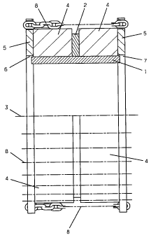
L'invention se rapporte à un rouleau d'entraînement mis en oeuvre dans une machine de traitement du bois et conçu pour amener des troncs d'arbres dans ladite machine. Ce rouleau d'entraînement se caractérise en ce qu'il comporte une bride (2) disposée sensiblement au centre de la jante (1) de roue et en ce qu'un tracé (4) de matière élastique est disposé de part et d'autre de la bride (2). Un anneau (5) est disposé sur le côté du tracé respectif (4) qui est opposé à la bride, ce qui permet aux anneaux (5) qui sont en aboutement avec les côtés externes du tracé élastique de part et d'autre de la roue de s'assembler au moyen de dispositifs de mise en tension (8).


Abrégé anglais


Feed roller in tree processing machinery for feeding
tree trunks through the machinery distinguished in that the
flange (2) is arranged essentially in the centre of the wheel rim
(1) and that a track (4) of elastic material is arranged on either
side of the flange (2). A ring (5) is arranged on the side of the
respective track (4) that is opposite the flange, whereby the rings
(5) that abut the outer sides of the elastic track on either side of the
wheel are joined with one another by means of tensioning devices
(8).


Revendications

Note : Les revendications sont présentées dans la langue officielle dans laquelle elles ont été soumises.


3

CLAIMS:


1. Feed roller for tree-processing machinery for
feeding tree trunks through the machinery characterised in
that it comprises an essentially cylindrically-shaped wheel
rim (1) with a radially outwardly facing flange (2) located
essentially at the centre of the wheel rim (1), a pair of
tracks (4) of elastic material each arranged on the wheel
rim on opposite sides of the flange (2) such that they abut
the flange (2), plus a pair of rings (5) each arranged on
the side of each track (4) opposite to the flange (2) such
that they abut the track (4), wherein the pair of rings (5)
abutting the outside of the tracks (4) are joined by means
of a tensioning device (8).


2. The feed roller of claim 1 wherein the flange (2)
has a plurality of holes or recesses adapted to receive the
elastic material of the tracks (4).


3. The feed roller of claim 1 or 2 wherein the
tensioning device is a chain.


4. The feed roller of any one of claims 1 to 3 which
further comprises attachment means for attaching the
tensioning device (8) to the rings (5) which attachment
means comprise an end piece projecting outwardly from each
of the rings (5) which end piece is provided with a hole for
receiving securing means.


5. Procedure for fitting a feed roller to tree-
processing machinery for feeding tree trunks through the
machinery characterised in that a ring-shaped track (4) of
elastic material is pushed onto either side of a wheel rim
(1) provided with an outwardly facing flange (2) located
essentially at the centre of the wheel rim such that the
track (4) abuts the flange (2), a ring (5) is applied to the


4


side of the track (4) opposite the flange (2) and a
tensioning device (8) is brought between the ring (5) and
another part of the feed roller on the opposite side of the
ring (5).


6. The procedure of claim 5 wherein the flange (2)
further comprises a plurality of holes or recesses which
receive the elastic material of the tracks (4).


7. The procedure of claim 5 or 6 wherein the
tensioning device is a chain.


8. The procedure of any one of claims 5 to 7 wherein
the tensioning device (8) is attached to the ring (5) by
means of an end piece projecting outwardly from the ring (5)
which end piece is provided with a hole for receiving
securing means.


9. The procedure of any one of claims 5 to 8 wherein
the another part of the feed roller on the opposite side of
the ring comprises an additional ring.


Description

Note : Les descriptions sont présentées dans la langue officielle dans laquelle elles ont été soumises.


CA 02394601 2007-12-06
20368-724

1
Feed roller and a method for assembling a feed roller
The present invention relates to a feed roller

used in tree-processing machinery to feed the trunk of the
tree through the machinery.

Such feed rollers used in tree-processing machines
or tree harvesters are normally equipped with a vulcanised
tread of, for example, rubber, attached to a wheel rim and
surrounded by cross-running chain links or a net of chain
links to attain a better grip when feeding the tree trunks

forward. When the desired function of the feed roller no
longer exists, the roller must be dismounted and equipped
with a new tread. The costs for dismounting and fitting, as
well as for a new feed roller, are substantial.

The present invention seeks to eliminate the said
disadvantages of known feed rollers and provide these with a
longer life length and thus lower operating costs.

In accordance with the present invention there is
provided feed roller for tree-processing machinery for
feeding tree trunks through the machinery characterised in

that it comprises an essentially cylindrically-shaped wheel
rim with a radially outwardly facing flange located
essentially at the centre of the wheel rim, a pair of tracks
of elastic material each arranged on the wheel rim on
opposite sides of the flange such that they abut the flange,

plus a pair of rings each arranged on the side of each track
opposite to the flange such that they abut the track,
wherein the pair of rings abutting the outside of the

tracks are joined by means of a tensioning device.


CA 02394601 2007-12-06
20368-724

la
In a further aspect of the present invention there
is provided procedure for fitting a feed roller to tree-
processing machinery for feeding tree trunks through the
machinery characterised in that a ring-shaped track of

elastic material is pushed onto either side of a wheel rim
provided with an outwardly facing flange located essentially
at the centre of the wheel rim such that the track abuts the
flange, a ring is applied to the side of the track opposite
the flange and a tensioning device is brought between the
ring and another part of the feed roller on the opposite
side of the ring.

An example of the invention will be described in
greater detail with reference to the drawing where Figs. 1
and 2 show schematically as two different embodiments an

upper half of the roller as a cross-section through it and a
lower half of the roller seen across the direction of its
axis.

1 designates a cylindrical roller or hub in the
form of a wheel rim 1, made of steel, for example, that
radially along its periphery and in the centre of the rim
has an outwardly projecting flange 2 that is, for example,
permanently attached by welding to the wheel rim, see

Fig. 1. The roller 1 is supported in the traditional manner
so that it can be driven to rotate around an axle 3. A

circular-shaped track 4 of elastic material, for example
rubber, that runs around the wheel rim is arranged on each
side of the flange 2. Each track 4 is pushed onto the
cylindrical wheel rim 1 so that it abuts the flange 2. A
rigid ring 5, made of steel, for example, whose inner

periphery 6 has a radius that is greater than the outer
diameter of the wheel rim 1 is brought onto the outside of
the respective track 4. This is evident at 7. The rings 5
are joined with one another by means of a tensioning


CA 02394601 2007-12-06
20368-724

lb
device 8, here shown in the form of chains, that increases
the friction between the roller and the tree trunk and thus
reduces the risk for slippage.

The intention with the tensioning device 8 is also
to draw the rings towards one another and thereby press the
elastic tracks 4 between themselves and the flange 2. This
means that this change in shape due to the tension between
the rings 5 will press the tracks 4 against the periphery of
the wheel rim 1, against the flange 2 as well as against the

rings 5, which means that the tracks 4 will be prevented
from slipping or sliding in relation to the rim


CA 02394601 2002-06-17
WO 01/47672 PCT/SEOO/02471
2
1. To further ensure that slidi 1g or slipping cannot occur, the flange 2 can
be provided with a
number of recesses or holes t iat pass all the way through in which the
material of the tracks 4
will expand and lock the traclcs 4 to the flange 2.
In the example shown, it is suggested that the tensioning device is chains 8
that
can be tensioned between the rings 5 (the chains in the example shown are
indicated only by
dotted and dashed lines). The actual clamping of the respective chain at the
rings can naturally
take place in a number of ways that are obvious for a person skilled in the
art. In the figure, it
is suggested that the respective chain 8 is provided with an end piece that
has a part that
projects out from the respective ring 5 and that is provided with an elongated
hole for
accommodating, for example, a cotter, so that it can be locked at the ring to
secure its
function.
When, for example, the tracks 4 have been worn down to such a degree that the
function of the feed roller is no longer satisfactory, the chains 8 are
loosened and the rings 5
removed. The tracks 4 can now be easily drawn off from the hub of the roller
and replaced by
new tracks that are locked into place by means of the rings 5 and chains 8 as
described
previously. On many occasions, the tracks are worn down to a greater extent at
one of their
edges, in which case they can exchange places or be turned around before they
are pushed
back onto the hub of the roller.
One advantage that is obtained automatically with the invention is that
stretching of the tensioning device 8 is achieved when the tracks 4 are
fitted.
It should be realised that the invention can be designed in a number of
different
ways within the scope of the characteristics of claim 1. It can be considered,
for example, to
position the flange on one of the sides of the wheel rim and use only one
elastic track 4 and
ring 5, whereby the tensioning device 8 will extend between the ring 5
abutting the one side
of the track and the flange 2, see Fig. 2.

---------------

Dessin représentatif
Une figure unique qui représente un dessin illustrant l'invention.
États administratifs

Pour une meilleure compréhension de l'état de la demande ou brevet qui figure sur cette page, la rubrique Mise en garde , et les descriptions de Brevet , États administratifs , Taxes périodiques et Historique des paiements devraient être consultées.

États administratifs

Titre Date
Date de délivrance prévu 2008-07-08
(86) Date de dépôt PCT 2000-12-08
(87) Date de publication PCT 2001-07-05
(85) Entrée nationale 2002-06-17
Requête d'examen 2003-11-06
(45) Délivré 2008-07-08
Expiré 2020-12-08

Historique d'abandonnement

Il n'y a pas d'historique d'abandonnement

Historique des paiements

Type de taxes Anniversaire Échéance Montant payé Date payée
Le dépôt d'une demande de brevet 300,00 $ 2002-06-17
Taxe de maintien en état - Demande - nouvelle loi 2 2002-12-09 100,00 $ 2002-06-17
Enregistrement de documents 100,00 $ 2002-10-01
Requête d'examen 400,00 $ 2003-11-06
Taxe de maintien en état - Demande - nouvelle loi 3 2003-12-08 100,00 $ 2003-11-19
Taxe de maintien en état - Demande - nouvelle loi 4 2004-12-08 100,00 $ 2004-11-10
Taxe de maintien en état - Demande - nouvelle loi 5 2005-12-08 200,00 $ 2005-11-15
Taxe de maintien en état - Demande - nouvelle loi 6 2006-12-08 200,00 $ 2006-11-14
Taxe de maintien en état - Demande - nouvelle loi 7 2007-12-10 200,00 $ 2007-11-28
Taxe finale 300,00 $ 2008-04-24
Taxe de maintien en état - brevet - nouvelle loi 8 2008-12-08 200,00 $ 2008-11-24
Taxe de maintien en état - brevet - nouvelle loi 9 2009-12-08 200,00 $ 2009-11-09
Taxe de maintien en état - brevet - nouvelle loi 10 2010-12-08 250,00 $ 2010-11-08
Taxe de maintien en état - brevet - nouvelle loi 11 2011-12-08 250,00 $ 2011-11-23
Taxe de maintien en état - brevet - nouvelle loi 12 2012-12-10 250,00 $ 2012-11-30
Taxe de maintien en état - brevet - nouvelle loi 13 2013-12-09 250,00 $ 2013-11-18
Taxe de maintien en état - brevet - nouvelle loi 14 2014-12-08 250,00 $ 2014-11-26
Taxe de maintien en état - brevet - nouvelle loi 15 2015-12-08 450,00 $ 2015-11-16
Taxe de maintien en état - brevet - nouvelle loi 16 2016-12-08 450,00 $ 2016-11-14
Taxe de maintien en état - brevet - nouvelle loi 17 2017-12-08 450,00 $ 2017-11-14
Taxe de maintien en état - brevet - nouvelle loi 18 2018-12-10 450,00 $ 2018-11-22
Taxe de maintien en état - brevet - nouvelle loi 19 2019-12-09 450,00 $ 2019-11-20
Titulaires au dossier

Les titulaires actuels et antérieures au dossier sont affichés en ordre alphabétique.

Titulaires actuels au dossier
PARTEK FOREST AB
Titulaires antérieures au dossier
NILSSON, GUNNAR
Les propriétaires antérieurs qui ne figurent pas dans la liste des « Propriétaires au dossier » apparaîtront dans d'autres documents au dossier.
Documents

Pour visionner les fichiers sélectionnés, entrer le code reCAPTCHA :


Pour visualiser une image, cliquer sur un lien dans la colonne description du document. Pour télécharger l'image (les images), cliquer l'une ou plusieurs cases à cocher dans la première colonne et ensuite cliquer sur le bouton "Télécharger sélection en format PDF (archive Zip)" ou le bouton "Télécharger sélection (en un fichier PDF fusionné)".

Liste des documents de brevet publiés et non publiés sur la BDBC .

Si vous avez des difficultés à accéder au contenu, veuillez communiquer avec le Centre de services à la clientèle au 1-866-997-1936, ou envoyer un courriel au Centre de service à la clientèle de l'OPIC.


Description du
Document 
Date
(yyyy-mm-dd) 
Nombre de pages   Taille de l'image (Ko) 
Page couverture 2002-11-15 1 37
Dessins représentatifs 2002-06-17 1 16
Abrégé 2002-06-17 2 61
Revendications 2002-06-17 1 44
Dessins 2002-06-17 2 31
Description 2002-06-17 2 107
Description 2006-11-03 4 143
Revendications 2006-11-03 2 60
Revendications 2007-12-06 2 60
Description 2007-12-06 4 142
Dessins représentatifs 2008-06-09 1 7
Page couverture 2008-06-09 2 39
Poursuite-Amendment 2006-05-04 3 59
PCT 2002-06-17 5 198
Cession 2002-06-17 2 91
Cession 2002-10-01 2 74
Poursuite-Amendment 2003-11-06 1 38
Poursuite-Amendment 2006-11-03 7 240
Poursuite-Amendment 2007-06-07 2 35
Poursuite-Amendment 2007-12-06 7 208
Correspondance 2008-04-24 1 38