Language selection

Search

Patent 2404677 Summary

Third-party information liability

Some of the information on this Web page has been provided by external sources. The Government of Canada is not responsible for the accuracy, reliability or currency of the information supplied by external sources. Users wishing to rely upon this information should consult directly with the source of the information. Content provided by external sources is not subject to official languages, privacy and accessibility requirements.

Claims and Abstract availability

Any discrepancies in the text and image of the Claims and Abstract are due to differing posting times. Text of the Claims and Abstract are posted:

  • At the time the application is open to public inspection;
  • At the time of issue of the patent (grant).
(12) Patent: (11) CA 2404677
(54) English Title: DEVICE FOR BLOCKING A SAFETY BRAKE FOR LIFT
(54) French Title: DISPOSITIF DE BLOCAGE DU FREIN DE SECURITE D'UN ASCENSEUR
Status: Deemed expired
Bibliographic Data
(51) International Patent Classification (IPC):
  • B66B 5/04 (2006.01)
  • B66B 5/18 (2006.01)
(72) Inventors :
  • MAURY, JULIEN (Switzerland)
  • HUGEL, STEFAN (Switzerland)
(73) Owners :
  • INVENTIO AG (Switzerland)
(71) Applicants :
  • INVENTIO AG (Switzerland)
(74) Agent: RICHES, MCKENZIE & HERBERT LLP
(74) Associate agent:
(45) Issued: 2010-07-20
(22) Filed Date: 2002-09-24
(41) Open to Public Inspection: 2003-03-28
Examination requested: 2007-07-10
Availability of licence: N/A
(25) Language of filing: English

Patent Cooperation Treaty (PCT): No

(30) Application Priority Data:
Application No. Country/Territory Date
01810946.2 European Patent Office (EPO) 2001-09-28

Abstracts

English Abstract

In this lift equipment a lift cage (2) is on the way down, wherein a halt at the bottom storey is scheduled. If the lift cage (2) does not halt at the bottom storey according to plan, the lift cage (2) in its further travel is caught by buffers (26). In that case a safety brake (16) can be tripped due to the inertia of a speed limiter (13) and a limiter cable (19). So that the undesired tripping of the safety brake (16) can be avoided in the case of buffer travel, there is provided in the lift shaft (1) a blocking element (27) which blocks the movement of a blocking lever (25) as soon as the lift cage (2) has gone down past the bottom storey. The blocked blocking lever (25) blocks one double lever (14) and, by way of a linkage (18), the other double lever (14). Tripping of the safety brake (16) is thus precluded.


French Abstract

Dans cet ascenseur, une cabine (2) descend jusqu'à un arrêt, prévu au niveau inférieur. Si la cabine (2) ne s'arrête pas au niveau inférieur comme prévu, des amortisseurs (26) immobilisent la cabine (2) après qu'elle a dépassé sa course nominale. En pareil cas, un frein de sécurité (16) peut se déclencher du fait de l'inertie d'un limiteur de vitesse (13) et d'un câble de freinage (19). Pour éviter le déclenchement intempestif du frein de sécurité (16), en cas de course jusqu'aux amortisseurs, la gaine d'ascenseur (1) est pourvue d'un élément de verrouillage (27) qui empêche le déplacement d'un levier de blocage (25) dès que la cabine (2) dépasse le niveau inférieur. Étant immobilisé, le levier de blocage (25) verrouille un double levier (14) et, grâce à une timonerie (18), un autre double levier (14). Le déclenchement du frein de sécurité (16) est ainsi interdit.

Claims

Note: Claims are shown in the official language in which they were submitted.


CLAIMS:


1. In lift equipment with a lift cage and a counterweight movable in a lift
shaft
having a buffer element at at least one end thereof and a safety brake which
operates when excess speed of the lift cage or the counterweight occurs, the
improvement comprising a blocking device for blocking operation of the safety
brake having a blocking lever connected to a trip lever mechanism of the
safety
brake and at least one blocking element arranged in the lift shaft to control
the
movement of the blocking lever.


2. The improvement of claim 1 wherein the blocking element comprises a
curved or angled track having a first end oriented to permit movement of the
blocking lever and a second end oriented to block movement of the blocking
lever.

3. The improvement of claim 2 wherein the blocking device blocks operation of
the safety brake on upper buffer travel of the lift cage or counterweight and
the
buffer element is located at a top of the lift shaft.


4. The improvement of claim 2 wherein the blocking device blocks operation of
the safety brake on lower buffer travel of the lift cage or counterweight and
the
buffer element is located at a bottom of the lift shaft.

Description

Note: Descriptions are shown in the official language in which they were submitted.


CA 02404677 2009-07-14

1
DEVICE FOR BLOCKING A SAFETY BRAKE FOR LIFT

The invention relates to lift equipment with a lift cage movable in a lift
shaft and with
a counterweight movable in the lift shaft, wherein the speed of the lift cage
or the
counterweight is monitored by means of a speed limiter device and the speed
limiter
device stops the lift cage or the counterweight by means of a safety brake in
the
case of excess speed of the lift cage or the counterweight.

In the case of lift equipment with a lift cage and counterweight movable in a
shaft the
speed of the lift cage or the counterweight is monitored. When excess speed
occurs
the lift cage or the counterweight is stopped by means of a safety brake. If,
for
example, the lift cage travels beyond the bottom storey in the downward
direction
with less than excess speed the lift cage is, on further travel thereof,
caught by
buffers. In that case, the safety brake can be tripped due to the inertia of
the speed
limiter and the limiter cable, whereby the braking elements of the safety
brake
wedge with the guide rails.

A disadvantage of known equipment resides in the fact that the lift cage has
to be
released from the brake. The safety brake has to be reset and the guide rails
checked at the braking location and the surface processed. Evacuation of the
lift
passengers can be undertaken only by expert personnel.

Here the invention will create a remedy. The invention meets the object of
avoiding
the disadvantages of the known equipment and of creating equipment by means of
which faulty trippings of the safety brake are avoided.

The advantages achieved by the invention are essentially to be seen in that
the
safety brake is not tripped in the case of buffer travel. The lift passengers
are thus
not exposed to extreme decelerations of the lift cage. Moreover, expert
personnel
are not needed for carrying out evacuation of the lift passengers. The lift
cage can,
after buffer travel, be manually moved to the next storey so that the lift
passengers
can leave the lift cage. Moreover, the mechanical components of the safety
brake,
and the speed limiter and the guide rails are treated gently. In the case of
buffer
tests, the safety brake is not tripped and the considerable effort for release
of the


CA 02404677 2009-07-14

2
brake is saved. In the case of approval tests, the safety brake is usually
blocked, so
that no instances of braking can occur in the shaft end regions in the event
of out-of-
the-ordinary test travels. With the equipment according to the invention,
safety is
guaranteed over the entire shaft height even in the case of approval tests.

In one aspect, the present invention provides a lift equipment with a lift
cage and a
counterweight movable in a lift shaft having a buffer element at at least one
end
thereof and a safety brake which operates when excess speed of the lift cage
or the
counterweight occurs, the improvement comprising a blocking device for
blocking
operation of the safety brake having a blocking lever connected to a trip
lever
mechanism of the safety brake and at least one blocking element arranged in
the lift
shaft to control the movement of the blocking lever.

The present invention is explained in more detail by reference to the
accompanying
figures, in which:

Fig. 1 shows lift equipment with a safety brake for stopping a lift cage and
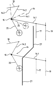
Fig. 2 shows details of a blocking device for blocking the safety brake.

Fig. 1 shows lift equipment with a lift cage 2 movable in a lift cage 2 and
connected
with a counterweight 4 by way of a cable 3. The cable 3 is driven in the
operational
case by means of a drive pulley of a drive unit 6. Lift cage 2 and
counterweight 4
are guided by means of guide rails 7 extending over the shaft height. The lift
equipment comprises a top storey with a top storey door 8, a second-to-top
storey
with a second-to-top storey door 10, further storeys with further storey doors
10 and
a bottom storey with a bottom storey door 11. The drive unit 6 and a speed
limiter
13, which monitors the speed of the lift cage 2 and stops the lift cage 2 if
excess
speed occurs, are arranged in a shaft head 12. A respective double lever 14,
which
is pivotably mounted at a fulcrum 15 of the lift cage 2, is provided at each
side of the
lift cage 2. A safety brake 16 for stopping the lift cage 2 is connected by
means of a
linkage 17 with one side 14.1 of the double lever 14, which side 14.1 is also
connected to limiter cable 19 of the speed limiter 13. The other side 14.2 of
one
double lever 14 is connected by means of a linkage 18 with the other double
lever. If
one side 14.1 of the double lever 14 is moved upwardly, then the safety brake
16
engaged, whereby braking elements wedging with the guide rails 7 stop the lift
cage


CA 02404677 2009-07-14

2a
in the case of emergency. In the operational case, the lift cage 2 drives the
limiter
cable 19 by means of the one side 14.1 of the double lever 14. In the case of
excess
speed of the lift cage 2, the speed limiter 13 blocks the limiter cable 19.
The one
side 14.1 of the double lever 14 is thereby deflected upwardly and the safety
brake
engaged at both sides of the lift cage 2.

The endless limiter cable 19 is tensioned by means of a deflecting roller 21
arranged
in a shaft pit 20, wherein a roller axle 21 is pivotably mounted at one end at
a
fulcrum 23 and carries a tensioning weight 24 at the other end.


CA 02404677 2002-09-24
3

A blocking lever 25 is connected at the fulcrum 15 with one double lever 14.
In the event
of tripping as mentioned above, one side 14.1 of one double lever 14 is
deflected
upwardly. At the same time, the blocking lever 25 is deflected in
anticlockwise sense.

Fig. 1 shows the lift cage 2, which has set off at the top storey, on the way
down, wherein
a halt at the second-from-bottom storey and subsequently at the bottom storey
is provided.
If, for example, the travel from the second-to-bottom storey to the bottom
storey runs at
less than excess speed and the lift cage 2 does not halt at the bottom storey,
the lift cage
2 on its further travel downwardly is caught by buffers 26. In that case, the
safety brake 16
can, due to the inertia of the speed limiter 13 and the limiter cable 19, be
tripped, whereby
the braking elements of the safety brake 16 wedge with the guide rails 7. In
order to avoid
undesired tripping of the safety brake 16 in the case of buffer travel of the
lift cage 2 or the
counterweight 4, there is provided in the lift shaft 1 at the top and bottom a
blocking
element 27 which biocks the movement of the blocking lever 25 as soon as the
lift cage 2
or the counterweight 4 has travelled downwardly past the bottom storey. When
the
counterweight 4 impinges on the buffer (not illustrated), the lift cage 2
hangs in the cable 3.
The upper blocking element 27 prevents tripping of the safety brake 16 at the
upper shaft
end. The blocked blocking lever 25 blocks one double lever 14 and, by way of
the linkage
18, the other double lever 14. Tripping of the safety brake 16 is thus
precluded.
If the counterweight is monitored by means of a safety brake, a blocking lever
and a
blocking element with the above-illustrated effect are provided.

At least one blocking element 27 is also provided at the upper shaft end if
the upper shaft
end also has buffers.

Fig. 1 shows lift equipment without a machine room. The equipment according to
the
invention for evacuation of lift passengers can also be used on lift equipment
with a
machine room.
Fig. 2 shows details of the blocking device, which is formed from the blocking
lever 25 and
blocking element 27, for blocking the safety brake 16 in the case of buffer
travel. The
blocking lever 25 illustrated by solid lines is shown in the position in which
the lift cage
stands at the bottom storey. The blocking lever 25 illustrated by dot-dashed
lines is shown
in the position in which the safety brake 16 is urged engaged. The movement of
the
blocking lever 25 is not blocked by the blocking element 27. The blocking
lever 27


CA 02404677 2002-09-24
4

illustrated by dashed lines is shown in the position in which the lift cage 2
has travelled
down past the bottom storey. The movement of the blocking lever 25 is blocked
by means
of the blocking element 27. The movement of the double lever 14 connected with
the
blocking lever 25 at the fulcrum 15 is thus also blocked. Tripping of the
safety brake 16 is
thus prevented.

Representative Drawing
A single figure which represents the drawing illustrating the invention.
Administrative Status

For a clearer understanding of the status of the application/patent presented on this page, the site Disclaimer , as well as the definitions for Patent , Administrative Status , Maintenance Fee  and Payment History  should be consulted.

Administrative Status

Title Date
Forecasted Issue Date 2010-07-20
(22) Filed 2002-09-24
(41) Open to Public Inspection 2003-03-28
Examination Requested 2007-07-10
(45) Issued 2010-07-20
Deemed Expired 2013-09-24

Abandonment History

There is no abandonment history.

Payment History

Fee Type Anniversary Year Due Date Amount Paid Paid Date
Registration of a document - section 124 $100.00 2002-09-24
Application Fee $300.00 2002-09-24
Maintenance Fee - Application - New Act 2 2004-09-24 $100.00 2004-08-25
Maintenance Fee - Application - New Act 3 2005-09-26 $100.00 2005-08-29
Maintenance Fee - Application - New Act 4 2006-09-25 $100.00 2006-08-31
Request for Examination $800.00 2007-07-10
Maintenance Fee - Application - New Act 5 2007-09-24 $200.00 2007-08-30
Maintenance Fee - Application - New Act 6 2008-09-24 $200.00 2008-08-27
Maintenance Fee - Application - New Act 7 2009-09-24 $200.00 2009-08-27
Final Fee $300.00 2010-05-04
Maintenance Fee - Patent - New Act 8 2010-09-24 $200.00 2010-09-09
Maintenance Fee - Patent - New Act 9 2011-09-26 $200.00 2011-09-08
Owners on Record

Note: Records showing the ownership history in alphabetical order.

Current Owners on Record
INVENTIO AG
Past Owners on Record
HUGEL, STEFAN
MAURY, JULIEN
Past Owners that do not appear in the "Owners on Record" listing will appear in other documentation within the application.
Documents

To view selected files, please enter reCAPTCHA code :


To view images, click a link in the Document Description column. To download the documents, select one or more checkboxes in the first column and then click the "Download Selected in PDF format (Zip Archive)" or the "Download Selected as Single PDF" button.

List of published and non-published patent-specific documents on the CPD .

If you have any difficulty accessing content, you can call the Client Service Centre at 1-866-997-1936 or send them an e-mail at CIPO Client Service Centre.


Document
Description 
Date
(yyyy-mm-dd) 
Number of pages   Size of Image (KB) 
Representative Drawing 2002-11-22 1 10
Cover Page 2003-03-04 1 41
Abstract 2002-09-24 1 19
Description 2002-09-24 4 173
Claims 2002-09-24 1 22
Drawings 2002-09-24 2 40
Description 2009-07-14 5 187
Claims 2009-07-14 1 27
Representative Drawing 2009-12-18 1 4
Cover Page 2010-07-08 2 39
Correspondence 2009-12-22 1 30
Assignment 2002-09-24 5 124
Prosecution-Amendment 2007-07-10 1 43
Prosecution-Amendment 2009-06-09 2 33
Prosecution-Amendment 2009-07-14 8 275
Correspondence 2010-05-04 1 50