Sélection de la langue

Search

Sommaire du brevet 2404677 

Énoncé de désistement de responsabilité concernant l'information provenant de tiers

Une partie des informations de ce site Web a été fournie par des sources externes. Le gouvernement du Canada n'assume aucune responsabilité concernant la précision, l'actualité ou la fiabilité des informations fournies par les sources externes. Les utilisateurs qui désirent employer cette information devraient consulter directement la source des informations. Le contenu fourni par les sources externes n'est pas assujetti aux exigences sur les langues officielles, la protection des renseignements personnels et l'accessibilité.

Disponibilité de l'Abrégé et des Revendications

L'apparition de différences dans le texte et l'image des Revendications et de l'Abrégé dépend du moment auquel le document est publié. Les textes des Revendications et de l'Abrégé sont affichés :

  • lorsque la demande peut être examinée par le public;
  • lorsque le brevet est émis (délivrance).
(12) Brevet: (11) CA 2404677
(54) Titre français: DISPOSITIF DE BLOCAGE DU FREIN DE SECURITE D'UN ASCENSEUR
(54) Titre anglais: DEVICE FOR BLOCKING A SAFETY BRAKE FOR LIFT
Statut: Réputé périmé
Données bibliographiques
(51) Classification internationale des brevets (CIB):
  • B66B 5/04 (2006.01)
  • B66B 5/18 (2006.01)
(72) Inventeurs :
  • MAURY, JULIEN (Suisse)
  • HUGEL, STEFAN (Suisse)
(73) Titulaires :
  • INVENTIO AG (Suisse)
(71) Demandeurs :
  • INVENTIO AG (Suisse)
(74) Agent: RICHES, MCKENZIE & HERBERT LLP
(74) Co-agent:
(45) Délivré: 2010-07-20
(22) Date de dépôt: 2002-09-24
(41) Mise à la disponibilité du public: 2003-03-28
Requête d'examen: 2007-07-10
Licence disponible: S.O.
(25) Langue des documents déposés: Anglais

Traité de coopération en matière de brevets (PCT): Non

(30) Données de priorité de la demande:
Numéro de la demande Pays / territoire Date
01810946.2 Office Européen des Brevets (OEB) 2001-09-28

Abrégés

Abrégé français

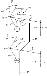
Dans cet ascenseur, une cabine (2) descend jusqu'à un arrêt, prévu au niveau inférieur. Si la cabine (2) ne s'arrête pas au niveau inférieur comme prévu, des amortisseurs (26) immobilisent la cabine (2) après qu'elle a dépassé sa course nominale. En pareil cas, un frein de sécurité (16) peut se déclencher du fait de l'inertie d'un limiteur de vitesse (13) et d'un câble de freinage (19). Pour éviter le déclenchement intempestif du frein de sécurité (16), en cas de course jusqu'aux amortisseurs, la gaine d'ascenseur (1) est pourvue d'un élément de verrouillage (27) qui empêche le déplacement d'un levier de blocage (25) dès que la cabine (2) dépasse le niveau inférieur. Étant immobilisé, le levier de blocage (25) verrouille un double levier (14) et, grâce à une timonerie (18), un autre double levier (14). Le déclenchement du frein de sécurité (16) est ainsi interdit.


Abrégé anglais

In this lift equipment a lift cage (2) is on the way down, wherein a halt at the bottom storey is scheduled. If the lift cage (2) does not halt at the bottom storey according to plan, the lift cage (2) in its further travel is caught by buffers (26). In that case a safety brake (16) can be tripped due to the inertia of a speed limiter (13) and a limiter cable (19). So that the undesired tripping of the safety brake (16) can be avoided in the case of buffer travel, there is provided in the lift shaft (1) a blocking element (27) which blocks the movement of a blocking lever (25) as soon as the lift cage (2) has gone down past the bottom storey. The blocked blocking lever (25) blocks one double lever (14) and, by way of a linkage (18), the other double lever (14). Tripping of the safety brake (16) is thus precluded.

Revendications

Note : Les revendications sont présentées dans la langue officielle dans laquelle elles ont été soumises.


CLAIMS:


1. In lift equipment with a lift cage and a counterweight movable in a lift
shaft
having a buffer element at at least one end thereof and a safety brake which
operates when excess speed of the lift cage or the counterweight occurs, the
improvement comprising a blocking device for blocking operation of the safety
brake having a blocking lever connected to a trip lever mechanism of the
safety
brake and at least one blocking element arranged in the lift shaft to control
the
movement of the blocking lever.


2. The improvement of claim 1 wherein the blocking element comprises a
curved or angled track having a first end oriented to permit movement of the
blocking lever and a second end oriented to block movement of the blocking
lever.

3. The improvement of claim 2 wherein the blocking device blocks operation of
the safety brake on upper buffer travel of the lift cage or counterweight and
the
buffer element is located at a top of the lift shaft.


4. The improvement of claim 2 wherein the blocking device blocks operation of
the safety brake on lower buffer travel of the lift cage or counterweight and
the
buffer element is located at a bottom of the lift shaft.

Description

Note : Les descriptions sont présentées dans la langue officielle dans laquelle elles ont été soumises.


CA 02404677 2009-07-14

1
DEVICE FOR BLOCKING A SAFETY BRAKE FOR LIFT

The invention relates to lift equipment with a lift cage movable in a lift
shaft and with
a counterweight movable in the lift shaft, wherein the speed of the lift cage
or the
counterweight is monitored by means of a speed limiter device and the speed
limiter
device stops the lift cage or the counterweight by means of a safety brake in
the
case of excess speed of the lift cage or the counterweight.

In the case of lift equipment with a lift cage and counterweight movable in a
shaft the
speed of the lift cage or the counterweight is monitored. When excess speed
occurs
the lift cage or the counterweight is stopped by means of a safety brake. If,
for
example, the lift cage travels beyond the bottom storey in the downward
direction
with less than excess speed the lift cage is, on further travel thereof,
caught by
buffers. In that case, the safety brake can be tripped due to the inertia of
the speed
limiter and the limiter cable, whereby the braking elements of the safety
brake
wedge with the guide rails.

A disadvantage of known equipment resides in the fact that the lift cage has
to be
released from the brake. The safety brake has to be reset and the guide rails
checked at the braking location and the surface processed. Evacuation of the
lift
passengers can be undertaken only by expert personnel.

Here the invention will create a remedy. The invention meets the object of
avoiding
the disadvantages of the known equipment and of creating equipment by means of
which faulty trippings of the safety brake are avoided.

The advantages achieved by the invention are essentially to be seen in that
the
safety brake is not tripped in the case of buffer travel. The lift passengers
are thus
not exposed to extreme decelerations of the lift cage. Moreover, expert
personnel
are not needed for carrying out evacuation of the lift passengers. The lift
cage can,
after buffer travel, be manually moved to the next storey so that the lift
passengers
can leave the lift cage. Moreover, the mechanical components of the safety
brake,
and the speed limiter and the guide rails are treated gently. In the case of
buffer
tests, the safety brake is not tripped and the considerable effort for release
of the


CA 02404677 2009-07-14

2
brake is saved. In the case of approval tests, the safety brake is usually
blocked, so
that no instances of braking can occur in the shaft end regions in the event
of out-of-
the-ordinary test travels. With the equipment according to the invention,
safety is
guaranteed over the entire shaft height even in the case of approval tests.

In one aspect, the present invention provides a lift equipment with a lift
cage and a
counterweight movable in a lift shaft having a buffer element at at least one
end
thereof and a safety brake which operates when excess speed of the lift cage
or the
counterweight occurs, the improvement comprising a blocking device for
blocking
operation of the safety brake having a blocking lever connected to a trip
lever
mechanism of the safety brake and at least one blocking element arranged in
the lift
shaft to control the movement of the blocking lever.

The present invention is explained in more detail by reference to the
accompanying
figures, in which:

Fig. 1 shows lift equipment with a safety brake for stopping a lift cage and
Fig. 2 shows details of a blocking device for blocking the safety brake.

Fig. 1 shows lift equipment with a lift cage 2 movable in a lift cage 2 and
connected
with a counterweight 4 by way of a cable 3. The cable 3 is driven in the
operational
case by means of a drive pulley of a drive unit 6. Lift cage 2 and
counterweight 4
are guided by means of guide rails 7 extending over the shaft height. The lift
equipment comprises a top storey with a top storey door 8, a second-to-top
storey
with a second-to-top storey door 10, further storeys with further storey doors
10 and
a bottom storey with a bottom storey door 11. The drive unit 6 and a speed
limiter
13, which monitors the speed of the lift cage 2 and stops the lift cage 2 if
excess
speed occurs, are arranged in a shaft head 12. A respective double lever 14,
which
is pivotably mounted at a fulcrum 15 of the lift cage 2, is provided at each
side of the
lift cage 2. A safety brake 16 for stopping the lift cage 2 is connected by
means of a
linkage 17 with one side 14.1 of the double lever 14, which side 14.1 is also
connected to limiter cable 19 of the speed limiter 13. The other side 14.2 of
one
double lever 14 is connected by means of a linkage 18 with the other double
lever. If
one side 14.1 of the double lever 14 is moved upwardly, then the safety brake
16
engaged, whereby braking elements wedging with the guide rails 7 stop the lift
cage


CA 02404677 2009-07-14

2a
in the case of emergency. In the operational case, the lift cage 2 drives the
limiter
cable 19 by means of the one side 14.1 of the double lever 14. In the case of
excess
speed of the lift cage 2, the speed limiter 13 blocks the limiter cable 19.
The one
side 14.1 of the double lever 14 is thereby deflected upwardly and the safety
brake
engaged at both sides of the lift cage 2.

The endless limiter cable 19 is tensioned by means of a deflecting roller 21
arranged
in a shaft pit 20, wherein a roller axle 21 is pivotably mounted at one end at
a
fulcrum 23 and carries a tensioning weight 24 at the other end.


CA 02404677 2002-09-24
3

A blocking lever 25 is connected at the fulcrum 15 with one double lever 14.
In the event
of tripping as mentioned above, one side 14.1 of one double lever 14 is
deflected
upwardly. At the same time, the blocking lever 25 is deflected in
anticlockwise sense.

Fig. 1 shows the lift cage 2, which has set off at the top storey, on the way
down, wherein
a halt at the second-from-bottom storey and subsequently at the bottom storey
is provided.
If, for example, the travel from the second-to-bottom storey to the bottom
storey runs at
less than excess speed and the lift cage 2 does not halt at the bottom storey,
the lift cage
2 on its further travel downwardly is caught by buffers 26. In that case, the
safety brake 16
can, due to the inertia of the speed limiter 13 and the limiter cable 19, be
tripped, whereby
the braking elements of the safety brake 16 wedge with the guide rails 7. In
order to avoid
undesired tripping of the safety brake 16 in the case of buffer travel of the
lift cage 2 or the
counterweight 4, there is provided in the lift shaft 1 at the top and bottom a
blocking
element 27 which biocks the movement of the blocking lever 25 as soon as the
lift cage 2
or the counterweight 4 has travelled downwardly past the bottom storey. When
the
counterweight 4 impinges on the buffer (not illustrated), the lift cage 2
hangs in the cable 3.
The upper blocking element 27 prevents tripping of the safety brake 16 at the
upper shaft
end. The blocked blocking lever 25 blocks one double lever 14 and, by way of
the linkage
18, the other double lever 14. Tripping of the safety brake 16 is thus
precluded.
If the counterweight is monitored by means of a safety brake, a blocking lever
and a
blocking element with the above-illustrated effect are provided.

At least one blocking element 27 is also provided at the upper shaft end if
the upper shaft
end also has buffers.

Fig. 1 shows lift equipment without a machine room. The equipment according to
the
invention for evacuation of lift passengers can also be used on lift equipment
with a
machine room.
Fig. 2 shows details of the blocking device, which is formed from the blocking
lever 25 and
blocking element 27, for blocking the safety brake 16 in the case of buffer
travel. The
blocking lever 25 illustrated by solid lines is shown in the position in which
the lift cage
stands at the bottom storey. The blocking lever 25 illustrated by dot-dashed
lines is shown
in the position in which the safety brake 16 is urged engaged. The movement of
the
blocking lever 25 is not blocked by the blocking element 27. The blocking
lever 27


CA 02404677 2002-09-24
4

illustrated by dashed lines is shown in the position in which the lift cage 2
has travelled
down past the bottom storey. The movement of the blocking lever 25 is blocked
by means
of the blocking element 27. The movement of the double lever 14 connected with
the
blocking lever 25 at the fulcrum 15 is thus also blocked. Tripping of the
safety brake 16 is
thus prevented.

Dessin représentatif
Une figure unique qui représente un dessin illustrant l'invention.
États administratifs

Pour une meilleure compréhension de l'état de la demande ou brevet qui figure sur cette page, la rubrique Mise en garde , et les descriptions de Brevet , États administratifs , Taxes périodiques et Historique des paiements devraient être consultées.

États administratifs

Titre Date
Date de délivrance prévu 2010-07-20
(22) Dépôt 2002-09-24
(41) Mise à la disponibilité du public 2003-03-28
Requête d'examen 2007-07-10
(45) Délivré 2010-07-20
Réputé périmé 2013-09-24

Historique d'abandonnement

Il n'y a pas d'historique d'abandonnement

Historique des paiements

Type de taxes Anniversaire Échéance Montant payé Date payée
Enregistrement de documents 100,00 $ 2002-09-24
Le dépôt d'une demande de brevet 300,00 $ 2002-09-24
Taxe de maintien en état - Demande - nouvelle loi 2 2004-09-24 100,00 $ 2004-08-25
Taxe de maintien en état - Demande - nouvelle loi 3 2005-09-26 100,00 $ 2005-08-29
Taxe de maintien en état - Demande - nouvelle loi 4 2006-09-25 100,00 $ 2006-08-31
Requête d'examen 800,00 $ 2007-07-10
Taxe de maintien en état - Demande - nouvelle loi 5 2007-09-24 200,00 $ 2007-08-30
Taxe de maintien en état - Demande - nouvelle loi 6 2008-09-24 200,00 $ 2008-08-27
Taxe de maintien en état - Demande - nouvelle loi 7 2009-09-24 200,00 $ 2009-08-27
Taxe finale 300,00 $ 2010-05-04
Taxe de maintien en état - brevet - nouvelle loi 8 2010-09-24 200,00 $ 2010-09-09
Taxe de maintien en état - brevet - nouvelle loi 9 2011-09-26 200,00 $ 2011-09-08
Titulaires au dossier

Les titulaires actuels et antérieures au dossier sont affichés en ordre alphabétique.

Titulaires actuels au dossier
INVENTIO AG
Titulaires antérieures au dossier
HUGEL, STEFAN
MAURY, JULIEN
Les propriétaires antérieurs qui ne figurent pas dans la liste des « Propriétaires au dossier » apparaîtront dans d'autres documents au dossier.
Documents

Pour visionner les fichiers sélectionnés, entrer le code reCAPTCHA :


Pour visualiser une image, cliquer sur un lien dans la colonne description du document. Pour télécharger l'image (les images), cliquer l'une ou plusieurs cases à cocher dans la première colonne et ensuite cliquer sur le bouton "Télécharger sélection en format PDF (archive Zip)" ou le bouton "Télécharger sélection (en un fichier PDF fusionné)".

Liste des documents de brevet publiés et non publiés sur la BDBC .

Si vous avez des difficultés à accéder au contenu, veuillez communiquer avec le Centre de services à la clientèle au 1-866-997-1936, ou envoyer un courriel au Centre de service à la clientèle de l'OPIC.


Description du
Document 
Date
(yyyy-mm-dd) 
Nombre de pages   Taille de l'image (Ko) 
Dessins représentatifs 2002-11-22 1 10
Page couverture 2003-03-04 1 41
Abrégé 2002-09-24 1 19
Description 2002-09-24 4 173
Revendications 2002-09-24 1 22
Dessins 2002-09-24 2 40
Description 2009-07-14 5 187
Revendications 2009-07-14 1 27
Dessins représentatifs 2009-12-18 1 4
Page couverture 2010-07-08 2 39
Correspondance 2009-12-22 1 30
Cession 2002-09-24 5 124
Poursuite-Amendment 2007-07-10 1 43
Poursuite-Amendment 2009-06-09 2 33
Poursuite-Amendment 2009-07-14 8 275
Correspondance 2010-05-04 1 50