Language selection

Search

Patent 2416565 Summary

Third-party information liability

Some of the information on this Web page has been provided by external sources. The Government of Canada is not responsible for the accuracy, reliability or currency of the information supplied by external sources. Users wishing to rely upon this information should consult directly with the source of the information. Content provided by external sources is not subject to official languages, privacy and accessibility requirements.

Claims and Abstract availability

Any discrepancies in the text and image of the Claims and Abstract are due to differing posting times. Text of the Claims and Abstract are posted:

  • At the time the application is open to public inspection;
  • At the time of issue of the patent (grant).
(12) Patent: (11) CA 2416565
(54) English Title: SYRINGE WITH A BARREL HOLDING A FLUID MEDIUM AND HAVING A SEALING CAP
(54) French Title: SERINGUE AVEC FUT PERMETTANT DE CONTENIR UN LIQUIDE ET EQUIPEE D'UN CAPUCHON OBTURATEUR
Status: Deemed expired
Bibliographic Data
(51) International Patent Classification (IPC):
  • A61M 5/31 (2006.01)
(72) Inventors :
  • WITOWSKI, NORBERT (Germany)
(73) Owners :
  • BAYER INTELLECTUAL PROPERTY GMBH (Not Available)
(71) Applicants :
  • SCHERING AKTIENGESELLSCHAFT (Germany)
(74) Agent: MARKS & CLERK
(74) Associate agent:
(45) Issued: 2009-12-08
(86) PCT Filing Date: 2001-08-01
(87) Open to Public Inspection: 2002-04-04
Examination requested: 2006-03-30
Availability of licence: N/A
(25) Language of filing: English

Patent Cooperation Treaty (PCT): Yes
(86) PCT Filing Number: PCT/EP2001/008896
(87) International Publication Number: WO2002/026296
(85) National Entry: 2003-01-29

(30) Application Priority Data:
Application No. Country/Territory Date
00121060.8 European Patent Office (EPO) 2000-09-27

Abstracts

English Abstract


A syringe is provided with a barrel 1 holding a fluid medium and a sealing cap
that is
put on the outlet end of the barrel. The barrel 1 in the section that can be
inserted into the cap
has a first locking element 8 on the outside. The sealing cap 2 in the
corresponding section
has interactive second locking elements 12 on the inside. In order that the
sealing cap can be
put onto barrel with little force and thus less cracking occurring, the cap
has a plurality of
second locking elements 12 that are arranged peripherally. In each case, an
expansion section
13 is provided in the wall of cap 2 between each pair of adjacent locking
elements 12.


French Abstract

L'invention concerne une seringue composée d'un cylindre (1) recevant un milieu liquide et d'un capuchon de fermeture logé côté sortie. Le cylindre (1) présente un premier élément d'encastrage (8) sur l'extérieur de la partie destinée à être introduite dans le capuchon. Le capuchon (2) présente sur l'intérieur de ladite partie des deuxièmes éléments d'encastrage (12) interagissant avec le premier. L'invention vise à permettre une mise en place avec une force réduite du capuchon de fermeture sur le cylindre (1), et à réduire par conséquent le risque de rupture. A cet effet, le capuchon (2) présente une pluralité de deuxièmes éléments d'encastrage (12) logés dans le sens périphérique. Une partie d'expansion (13) est prévue dans la paroi du capuchon (2) respectivement entre deux éléments d'encastrage (12) adjacents.

Claims

Note: Claims are shown in the official language in which they were submitted.


4
The embodiments of the invention in which an exclusive property or privilege
is
claimed are defined as follows:

1. A syringe having a cylinder for accommodating a fluid medium and having,
mounted at the outlet end, a closure cap having a cover provided with a
sealable outlet;
the cylinder having externally, on the portion arranged to be inserted into
the cap, a first
locking element, and the cap having internally, on the corresponding portion,
second
locking elements co-operating therewith;
the cap having a plurality of second locking elements arranged in a peripheral
direction;
an expansion portion, which is elongate in the axial direction of the closure
cap, being
provided in the wall of the cap between two locking elements adjacent to one
another;
and
the expansion portion extending, seen in the axial direction of the cap,
beyond the
extents, seen in the axial direction, of the second locking elements, wherein:
the end of the expansion portion which faces the open end of the closure cap
is spaced
apart from the open end of the closure cap; and
the first locking element is in the form of a nose, which projects out above
the cylinder
surface and which, on a portion facing the outlet end, is bevelled off and
which, on the
second portion remote from the outlet end, has a shoulder running virtually
perpendicular
to the outer surface of the cylinder.

2. A syringe having a cylinder for accommodating a fluid medium and having,
mounted at the outlet end, a closure cap having a cover provided with a
sealable outlet;
the cylinder having externally, on the portion arranged to be inserted into
the cap, a first

locking element, and the cap having internally, on the corresponding portion,
second
locking elements co-operating therewith;
the cap having a plurality of second locking elements arranged in a peripheral
direction,
an expansion portion, which is elongate in the axial direction of the closure
cap, being
provided in the wall of the cap between two locking elements adjacent to one
another,
and
the expansion portion extending, seen in the axial direction of the cap,
beyond the
extents, seen in the axial direction, of the second locking elements, wherein:


the end of the expansion portion which faces the open end of the closure cap
is spaced
apart from the open end of the closure cap; and
the first locking element is in the form of a recess extending in a peripheral
direction,
which, on a portion remote from the outlet end, is bevelled off and which, on
the second
portion, which faces the outlet end, has a shoulder running virtually
perpendicular to the
outer surface of the cylinder.

3. A syringe according to claim 1 or 2, wherein the expansion portion is in
the form
of a thinner wall portion.

4. A syringe according to claim 1, wherein the expansion portion is in the
form of a
recess.

5. A syringe according to any one of claims 1 to 4, wherein the number of
second
locking elements is at least six, the locking elements being distributed in a
peripheral
direction and having respective expansion portions provided between them.

Description

Note: Descriptions are shown in the official language in which they were submitted.


CA 02416565 2009-01-27

Syringe With A Barrel Holding A Fluid Medium
And Having A Sealing Cap

The invention relates to a syringe for holding a fluid medium and having a
sealing cap.
Such a syringe is known from EP 0 723 784 A. The barrel has a lug that extends
in the
peripheral direction with an inclined side facing the outlet and a rear
shoulder that is almost
perpendicular to the peripheral direction. On its inside, the cap that is to
be put on has sections
that are formed as undercuts and that extend in the peripheral direction, and
the cap engages
in the projecting section of the barrel when the cap is pushed on. Since the
outside diameter of
the projecting,section of the barrel is larger than the inside diameter of the
cap, a considerable
compressive force can be used when the cap is put on. This is all the more
true as the
projecting element must be relatively large so that deviations from the
container dimensions
can be compensated for.

An object of the invention is to provide an improved syringe of the type
mentioned
above.

This object may be solved by a syringe having a cylinder for accommodating a
fluid medium and having, mounted at the outlet end, a closure cap having a
cover
provided with a sealable outlet;
the cylinder having externally, on the portion arranged to be inserted into
the cap, a first
locking element, and the cap having internally, on the corresponding portion,
second
locking elements co-operating therewith;
the cap having a plurality of second locking elements arranged in a peripheral
direction;
an expansion portion, which is elongate in the axial direction of the closure
cap, being
provided in the wall of the cap between two locking elements adjacent to one
another;
and
the expansion portion extending, seen in the axial direction of the cap,
beyond the
extents, seen in the axial direction, of the second locking elements, wherein:
the end of the expansion portion which faces the open end of the closure cap
is spaced
apart from the open end of the closure cap; and
the first locking element is in the form of a nose, which projects out above
the cylinder
surface and which, on a portion facing the outlet end, is bevelled off and
which, on the
second portion remote from the outlet end, has a shoulder running virtually
perpendicular
to the outer surface of the cylinder.

. . . , ._ ...... .. ..~ . .. . . . . . .... .. ..... ... ... . . . ...
CA 02416565 2009-01-27

la
It is achieved by this design that the compressive pressure can be lower to
put on the
sealing cap, which in turn has the result that the number of cases in which
the container is
damaged during closing is reduced.

Other features and the suitability of the invention follow from the
description of the
embodiments based on the figures. Here, the figures show:

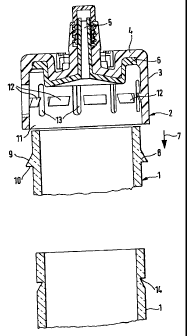
Fig. 1 a section through the outlet-side end of a barrel and through the
sealing cap that
is to be put on, and

Fig. 2 a second embodiment of the outlet-side end of the barrel.
Fig.l shows the outlet-side end of a barrel 1, on which a sealing cap 2 is put
for outlet-
side sealing. In a known way, barrel 1 has a seal on its inlet side and a
sealable plunger in the
inside to extrude the medium that is to be held in the barrel. Barrel 1 is
designed as a glass
barrel, and sealing cap 2 is preferably made of a chlorobutyl rubber or
another elastic material
having similar properties.

Sealing cap 2 is designed cup-shaped and has a cylindrical wall section 3,
which is
open to the end facing the barrel and has a cover 4 on the opposite end,
whereby the cover
has a sealable outlet 5 in a known way. Inside of the cover, a seal 6 is
provided. Sealing cap 2
is pushed open to seal the syringe body in the direction of arrow 7 on the
outlet-side end of
barrel 1.


CA 02416565 2003-01-29
2

At a predetermined distance from its outlet-side end, barrel 1 has a first
locking
element 8 that extends around the entire periphery thereof which has a cross-
section of a
sawtooth shape and is tilted like a ramp on its shoulder 9 that faces the
outlet-side end, while
second shoulder 10 that faces away from the outlet-side end, extends almost
perpendicularly
to the barrel surface.
At a predetermined distance from open end 11 of the cap 2, a plurality of
second
locking elements 12 that are offset against one another in peripheral
direction are provided on
the inside wall. The cross-sections of said locking elements are also designed
in an
approximately sawtooth shape and have a shoulder that is in turn inclined on
its side that faces
open end 11 and a shoulder that runs almost perpendicular to the wall of the
wall section on
its side that faces away from open end 11. The second shoulders lie in a plane
that runs
perpendicular to the axis of symmetry of the sealing cap. The distance of this
plane from open
end 11 or from the base of seal 6 is selected in such a way that the sealing
cap can be pushed
on just to the outlet-side end of barrel 1 so that when the free edge of the
barrel adjoins seal 6,
second locking elements 12 are slid over first locking element 8, and the two
elements make
contact and lock with their almost perpendicular shoulders.
As Fig. 1 shows, a longitudinal slot 13 that extends parallel to the axis of
symmetry in
the wall of the sealing cap is provided between, in each case, two adjacent
second locking
elements 12. It is arranged symmetrically between, in each case, two adjacent
locking
elements and extends both upward to the sealed bottom of the sealing cap and
also downward
to open end 11 beyond the length of locking elements 12.
At least six second locking elements are preferably provided offset against
one another
in peripheral direction. An embodiment with a number from eight two ten and
corresponding
longitudinal slots 13 arranged in between in each case is quite especially
advantageous.
The embodiment that is shown in Fig. 2 is distinguished from the one first
described
only in that instead of first locking element 8, an annular undercut 14 is
provided, which is
designed in such a way that second locking elements 12 project inwardly to
engage in the
undercut to ensure locking when sealing cap 2 is pushed on.
Longitudinal slots 13 are used as expansion sections and facilitate pushing
the sealing
cap onto the end of the barrel. The above-discussed number of second locking
elements 12
that are arranged according to peripheral direction also contributes to the
fact that together
with the longitudinal slots, a pushing with less pressure is possible.
In the above-described embodiment, the expansion sections that are formed by
longitudinal slots 13 are designed as recesses that extend through the entire
wall. As an
SZ 87/JM/am


CA 02416565 2003-01-29
3
alternative, it can also be provided that the expansion strips are made only
as recesses that do
not go through the entire wall. In both cases, the axial length and the width
of the expansion
strips is selected based on the material that forms the sealing cap and its
elasticity properties.
In this case, the barrel itself is preferably made of glass.

The requirements for the materials of glass plunger, inlet-side seal, outlet-
side sealing
cap and plunger, which together form a glass cartridge, are high, since they
are sterilized both
in unassembled state and as assembled syringes at about 120 C over an extended
period of,
for example, 30 minutes with superheated water.

SZ 87/JM/am

Representative Drawing
A single figure which represents the drawing illustrating the invention.
Administrative Status

For a clearer understanding of the status of the application/patent presented on this page, the site Disclaimer , as well as the definitions for Patent , Administrative Status , Maintenance Fee  and Payment History  should be consulted.

Administrative Status

Title Date
Forecasted Issue Date 2009-12-08
(86) PCT Filing Date 2001-08-01
(87) PCT Publication Date 2002-04-04
(85) National Entry 2003-01-29
Examination Requested 2006-03-30
(45) Issued 2009-12-08
Deemed Expired 2016-08-01

Abandonment History

There is no abandonment history.

Payment History

Fee Type Anniversary Year Due Date Amount Paid Paid Date
Application Fee $300.00 2003-01-29
Maintenance Fee - Application - New Act 2 2003-08-01 $100.00 2003-01-29
Registration of a document - section 124 $100.00 2003-07-11
Maintenance Fee - Application - New Act 3 2004-08-02 $100.00 2004-07-27
Maintenance Fee - Application - New Act 4 2005-08-01 $100.00 2005-07-21
Request for Examination $800.00 2006-03-30
Maintenance Fee - Application - New Act 5 2006-08-01 $200.00 2006-07-14
Maintenance Fee - Application - New Act 6 2007-08-01 $200.00 2007-07-19
Maintenance Fee - Application - New Act 7 2008-08-01 $200.00 2008-07-18
Maintenance Fee - Application - New Act 8 2009-08-03 $200.00 2009-07-22
Final Fee $300.00 2009-09-25
Registration of a document - section 124 $100.00 2010-01-19
Maintenance Fee - Patent - New Act 9 2010-08-02 $200.00 2010-07-15
Maintenance Fee - Patent - New Act 10 2011-08-01 $250.00 2011-07-21
Maintenance Fee - Patent - New Act 11 2012-08-01 $250.00 2012-07-17
Registration of a document - section 124 $100.00 2013-06-17
Maintenance Fee - Patent - New Act 12 2013-08-01 $250.00 2013-07-17
Maintenance Fee - Patent - New Act 13 2014-08-01 $250.00 2014-07-24
Owners on Record

Note: Records showing the ownership history in alphabetical order.

Current Owners on Record
BAYER INTELLECTUAL PROPERTY GMBH
Past Owners on Record
BAYER SCHERING PHARMA AKTIENGESELLSCHAFT
SCHERING AKTIENGESELLSCHAFT
WITOWSKI, NORBERT
Past Owners that do not appear in the "Owners on Record" listing will appear in other documentation within the application.
Documents

To view selected files, please enter reCAPTCHA code :


To view images, click a link in the Document Description column. To download the documents, select one or more checkboxes in the first column and then click the "Download Selected in PDF format (Zip Archive)" or the "Download Selected as Single PDF" button.

List of published and non-published patent-specific documents on the CPD .

If you have any difficulty accessing content, you can call the Client Service Centre at 1-866-997-1936 or send them an e-mail at CIPO Client Service Centre.


Document
Description 
Date
(yyyy-mm-dd) 
Number of pages   Size of Image (KB) 
Abstract 2003-01-29 1 16
Claims 2003-01-29 2 45
Drawings 2003-01-29 1 18
Description 2003-01-29 3 132
Representative Drawing 2003-03-21 1 9
Cover Page 2003-03-21 2 46
Abstract 2009-11-13 1 16
Description 2009-01-27 4 161
Claims 2009-01-27 2 71
Representative Drawing 2009-11-19 1 8
Cover Page 2009-11-19 2 43
PCT 2003-01-29 8 261
Assignment 2003-01-29 2 94
Correspondence 2003-03-19 1 25
Assignment 2003-07-11 2 64
Prosecution-Amendment 2006-02-08 1 30
Prosecution-Amendment 2006-03-30 1 31
Prosecution-Amendment 2008-07-29 3 90
Prosecution-Amendment 2009-01-27 6 203
Prosecution-Amendment 2009-02-19 1 17
Prosecution-Amendment 2009-02-25 1 25
Correspondence 2009-04-20 1 30
Correspondence 2009-09-25 1 31
Assignment 2010-01-19 5 175
Assignment 2013-06-17 8 210