Sélection de la langue

Search

Sommaire du brevet 2416565 

Énoncé de désistement de responsabilité concernant l'information provenant de tiers

Une partie des informations de ce site Web a été fournie par des sources externes. Le gouvernement du Canada n'assume aucune responsabilité concernant la précision, l'actualité ou la fiabilité des informations fournies par les sources externes. Les utilisateurs qui désirent employer cette information devraient consulter directement la source des informations. Le contenu fourni par les sources externes n'est pas assujetti aux exigences sur les langues officielles, la protection des renseignements personnels et l'accessibilité.

Disponibilité de l'Abrégé et des Revendications

L'apparition de différences dans le texte et l'image des Revendications et de l'Abrégé dépend du moment auquel le document est publié. Les textes des Revendications et de l'Abrégé sont affichés :

  • lorsque la demande peut être examinée par le public;
  • lorsque le brevet est émis (délivrance).
(12) Brevet: (11) CA 2416565
(54) Titre français: SERINGUE AVEC FUT PERMETTANT DE CONTENIR UN LIQUIDE ET EQUIPEE D'UN CAPUCHON OBTURATEUR
(54) Titre anglais: SYRINGE WITH A BARREL HOLDING A FLUID MEDIUM AND HAVING A SEALING CAP
Statut: Réputé périmé
Données bibliographiques
(51) Classification internationale des brevets (CIB):
  • A61M 5/31 (2006.01)
(72) Inventeurs :
  • WITOWSKI, NORBERT (Allemagne)
(73) Titulaires :
  • BAYER INTELLECTUAL PROPERTY GMBH (Non disponible)
(71) Demandeurs :
  • SCHERING AKTIENGESELLSCHAFT (Allemagne)
(74) Agent: MARKS & CLERK
(74) Co-agent:
(45) Délivré: 2009-12-08
(86) Date de dépôt PCT: 2001-08-01
(87) Mise à la disponibilité du public: 2002-04-04
Requête d'examen: 2006-03-30
Licence disponible: S.O.
(25) Langue des documents déposés: Anglais

Traité de coopération en matière de brevets (PCT): Oui
(86) Numéro de la demande PCT: PCT/EP2001/008896
(87) Numéro de publication internationale PCT: WO2002/026296
(85) Entrée nationale: 2003-01-29

(30) Données de priorité de la demande:
Numéro de la demande Pays / territoire Date
00121060.8 Office Européen des Brevets (OEB) 2000-09-27

Abrégés

Abrégé français

L'invention concerne une seringue composée d'un cylindre (1) recevant un milieu liquide et d'un capuchon de fermeture logé côté sortie. Le cylindre (1) présente un premier élément d'encastrage (8) sur l'extérieur de la partie destinée à être introduite dans le capuchon. Le capuchon (2) présente sur l'intérieur de ladite partie des deuxièmes éléments d'encastrage (12) interagissant avec le premier. L'invention vise à permettre une mise en place avec une force réduite du capuchon de fermeture sur le cylindre (1), et à réduire par conséquent le risque de rupture. A cet effet, le capuchon (2) présente une pluralité de deuxièmes éléments d'encastrage (12) logés dans le sens périphérique. Une partie d'expansion (13) est prévue dans la paroi du capuchon (2) respectivement entre deux éléments d'encastrage (12) adjacents.


Abrégé anglais


A syringe is provided with a barrel 1 holding a fluid medium and a sealing cap
that is
put on the outlet end of the barrel. The barrel 1 in the section that can be
inserted into the cap
has a first locking element 8 on the outside. The sealing cap 2 in the
corresponding section
has interactive second locking elements 12 on the inside. In order that the
sealing cap can be
put onto barrel with little force and thus less cracking occurring, the cap
has a plurality of
second locking elements 12 that are arranged peripherally. In each case, an
expansion section
13 is provided in the wall of cap 2 between each pair of adjacent locking
elements 12.

Revendications

Note : Les revendications sont présentées dans la langue officielle dans laquelle elles ont été soumises.


4
The embodiments of the invention in which an exclusive property or privilege
is
claimed are defined as follows:

1. A syringe having a cylinder for accommodating a fluid medium and having,
mounted at the outlet end, a closure cap having a cover provided with a
sealable outlet;
the cylinder having externally, on the portion arranged to be inserted into
the cap, a first
locking element, and the cap having internally, on the corresponding portion,
second
locking elements co-operating therewith;
the cap having a plurality of second locking elements arranged in a peripheral
direction;
an expansion portion, which is elongate in the axial direction of the closure
cap, being
provided in the wall of the cap between two locking elements adjacent to one
another;
and
the expansion portion extending, seen in the axial direction of the cap,
beyond the
extents, seen in the axial direction, of the second locking elements, wherein:
the end of the expansion portion which faces the open end of the closure cap
is spaced
apart from the open end of the closure cap; and
the first locking element is in the form of a nose, which projects out above
the cylinder
surface and which, on a portion facing the outlet end, is bevelled off and
which, on the
second portion remote from the outlet end, has a shoulder running virtually
perpendicular
to the outer surface of the cylinder.

2. A syringe having a cylinder for accommodating a fluid medium and having,
mounted at the outlet end, a closure cap having a cover provided with a
sealable outlet;
the cylinder having externally, on the portion arranged to be inserted into
the cap, a first

locking element, and the cap having internally, on the corresponding portion,
second
locking elements co-operating therewith;
the cap having a plurality of second locking elements arranged in a peripheral
direction,
an expansion portion, which is elongate in the axial direction of the closure
cap, being
provided in the wall of the cap between two locking elements adjacent to one
another,
and
the expansion portion extending, seen in the axial direction of the cap,
beyond the
extents, seen in the axial direction, of the second locking elements, wherein:


the end of the expansion portion which faces the open end of the closure cap
is spaced
apart from the open end of the closure cap; and
the first locking element is in the form of a recess extending in a peripheral
direction,
which, on a portion remote from the outlet end, is bevelled off and which, on
the second
portion, which faces the outlet end, has a shoulder running virtually
perpendicular to the
outer surface of the cylinder.

3. A syringe according to claim 1 or 2, wherein the expansion portion is in
the form
of a thinner wall portion.

4. A syringe according to claim 1, wherein the expansion portion is in the
form of a
recess.

5. A syringe according to any one of claims 1 to 4, wherein the number of
second
locking elements is at least six, the locking elements being distributed in a
peripheral
direction and having respective expansion portions provided between them.

Description

Note : Les descriptions sont présentées dans la langue officielle dans laquelle elles ont été soumises.


CA 02416565 2009-01-27

Syringe With A Barrel Holding A Fluid Medium
And Having A Sealing Cap

The invention relates to a syringe for holding a fluid medium and having a
sealing cap.
Such a syringe is known from EP 0 723 784 A. The barrel has a lug that extends
in the
peripheral direction with an inclined side facing the outlet and a rear
shoulder that is almost
perpendicular to the peripheral direction. On its inside, the cap that is to
be put on has sections
that are formed as undercuts and that extend in the peripheral direction, and
the cap engages
in the projecting section of the barrel when the cap is pushed on. Since the
outside diameter of
the projecting,section of the barrel is larger than the inside diameter of the
cap, a considerable
compressive force can be used when the cap is put on. This is all the more
true as the
projecting element must be relatively large so that deviations from the
container dimensions
can be compensated for.

An object of the invention is to provide an improved syringe of the type
mentioned
above.

This object may be solved by a syringe having a cylinder for accommodating a
fluid medium and having, mounted at the outlet end, a closure cap having a
cover
provided with a sealable outlet;
the cylinder having externally, on the portion arranged to be inserted into
the cap, a first
locking element, and the cap having internally, on the corresponding portion,
second
locking elements co-operating therewith;
the cap having a plurality of second locking elements arranged in a peripheral
direction;
an expansion portion, which is elongate in the axial direction of the closure
cap, being
provided in the wall of the cap between two locking elements adjacent to one
another;
and
the expansion portion extending, seen in the axial direction of the cap,
beyond the
extents, seen in the axial direction, of the second locking elements, wherein:
the end of the expansion portion which faces the open end of the closure cap
is spaced
apart from the open end of the closure cap; and
the first locking element is in the form of a nose, which projects out above
the cylinder
surface and which, on a portion facing the outlet end, is bevelled off and
which, on the
second portion remote from the outlet end, has a shoulder running virtually
perpendicular
to the outer surface of the cylinder.

. . . , ._ ...... .. ..~ . .. . . . . . .... .. ..... ... ... . . . ...
CA 02416565 2009-01-27

la
It is achieved by this design that the compressive pressure can be lower to
put on the
sealing cap, which in turn has the result that the number of cases in which
the container is
damaged during closing is reduced.

Other features and the suitability of the invention follow from the
description of the
embodiments based on the figures. Here, the figures show:

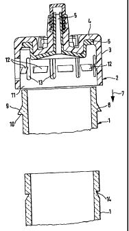
Fig. 1 a section through the outlet-side end of a barrel and through the
sealing cap that
is to be put on, and

Fig. 2 a second embodiment of the outlet-side end of the barrel.
Fig.l shows the outlet-side end of a barrel 1, on which a sealing cap 2 is put
for outlet-
side sealing. In a known way, barrel 1 has a seal on its inlet side and a
sealable plunger in the
inside to extrude the medium that is to be held in the barrel. Barrel 1 is
designed as a glass
barrel, and sealing cap 2 is preferably made of a chlorobutyl rubber or
another elastic material
having similar properties.

Sealing cap 2 is designed cup-shaped and has a cylindrical wall section 3,
which is
open to the end facing the barrel and has a cover 4 on the opposite end,
whereby the cover
has a sealable outlet 5 in a known way. Inside of the cover, a seal 6 is
provided. Sealing cap 2
is pushed open to seal the syringe body in the direction of arrow 7 on the
outlet-side end of
barrel 1.


CA 02416565 2003-01-29
2

At a predetermined distance from its outlet-side end, barrel 1 has a first
locking
element 8 that extends around the entire periphery thereof which has a cross-
section of a
sawtooth shape and is tilted like a ramp on its shoulder 9 that faces the
outlet-side end, while
second shoulder 10 that faces away from the outlet-side end, extends almost
perpendicularly
to the barrel surface.
At a predetermined distance from open end 11 of the cap 2, a plurality of
second
locking elements 12 that are offset against one another in peripheral
direction are provided on
the inside wall. The cross-sections of said locking elements are also designed
in an
approximately sawtooth shape and have a shoulder that is in turn inclined on
its side that faces
open end 11 and a shoulder that runs almost perpendicular to the wall of the
wall section on
its side that faces away from open end 11. The second shoulders lie in a plane
that runs
perpendicular to the axis of symmetry of the sealing cap. The distance of this
plane from open
end 11 or from the base of seal 6 is selected in such a way that the sealing
cap can be pushed
on just to the outlet-side end of barrel 1 so that when the free edge of the
barrel adjoins seal 6,
second locking elements 12 are slid over first locking element 8, and the two
elements make
contact and lock with their almost perpendicular shoulders.
As Fig. 1 shows, a longitudinal slot 13 that extends parallel to the axis of
symmetry in
the wall of the sealing cap is provided between, in each case, two adjacent
second locking
elements 12. It is arranged symmetrically between, in each case, two adjacent
locking
elements and extends both upward to the sealed bottom of the sealing cap and
also downward
to open end 11 beyond the length of locking elements 12.
At least six second locking elements are preferably provided offset against
one another
in peripheral direction. An embodiment with a number from eight two ten and
corresponding
longitudinal slots 13 arranged in between in each case is quite especially
advantageous.
The embodiment that is shown in Fig. 2 is distinguished from the one first
described
only in that instead of first locking element 8, an annular undercut 14 is
provided, which is
designed in such a way that second locking elements 12 project inwardly to
engage in the
undercut to ensure locking when sealing cap 2 is pushed on.
Longitudinal slots 13 are used as expansion sections and facilitate pushing
the sealing
cap onto the end of the barrel. The above-discussed number of second locking
elements 12
that are arranged according to peripheral direction also contributes to the
fact that together
with the longitudinal slots, a pushing with less pressure is possible.
In the above-described embodiment, the expansion sections that are formed by
longitudinal slots 13 are designed as recesses that extend through the entire
wall. As an
SZ 87/JM/am


CA 02416565 2003-01-29
3
alternative, it can also be provided that the expansion strips are made only
as recesses that do
not go through the entire wall. In both cases, the axial length and the width
of the expansion
strips is selected based on the material that forms the sealing cap and its
elasticity properties.
In this case, the barrel itself is preferably made of glass.

The requirements for the materials of glass plunger, inlet-side seal, outlet-
side sealing
cap and plunger, which together form a glass cartridge, are high, since they
are sterilized both
in unassembled state and as assembled syringes at about 120 C over an extended
period of,
for example, 30 minutes with superheated water.

SZ 87/JM/am

Dessin représentatif
Une figure unique qui représente un dessin illustrant l'invention.
États administratifs

Pour une meilleure compréhension de l'état de la demande ou brevet qui figure sur cette page, la rubrique Mise en garde , et les descriptions de Brevet , États administratifs , Taxes périodiques et Historique des paiements devraient être consultées.

États administratifs

Titre Date
Date de délivrance prévu 2009-12-08
(86) Date de dépôt PCT 2001-08-01
(87) Date de publication PCT 2002-04-04
(85) Entrée nationale 2003-01-29
Requête d'examen 2006-03-30
(45) Délivré 2009-12-08
Réputé périmé 2016-08-01

Historique d'abandonnement

Il n'y a pas d'historique d'abandonnement

Historique des paiements

Type de taxes Anniversaire Échéance Montant payé Date payée
Le dépôt d'une demande de brevet 300,00 $ 2003-01-29
Taxe de maintien en état - Demande - nouvelle loi 2 2003-08-01 100,00 $ 2003-01-29
Enregistrement de documents 100,00 $ 2003-07-11
Taxe de maintien en état - Demande - nouvelle loi 3 2004-08-02 100,00 $ 2004-07-27
Taxe de maintien en état - Demande - nouvelle loi 4 2005-08-01 100,00 $ 2005-07-21
Requête d'examen 800,00 $ 2006-03-30
Taxe de maintien en état - Demande - nouvelle loi 5 2006-08-01 200,00 $ 2006-07-14
Taxe de maintien en état - Demande - nouvelle loi 6 2007-08-01 200,00 $ 2007-07-19
Taxe de maintien en état - Demande - nouvelle loi 7 2008-08-01 200,00 $ 2008-07-18
Taxe de maintien en état - Demande - nouvelle loi 8 2009-08-03 200,00 $ 2009-07-22
Taxe finale 300,00 $ 2009-09-25
Enregistrement de documents 100,00 $ 2010-01-19
Taxe de maintien en état - brevet - nouvelle loi 9 2010-08-02 200,00 $ 2010-07-15
Taxe de maintien en état - brevet - nouvelle loi 10 2011-08-01 250,00 $ 2011-07-21
Taxe de maintien en état - brevet - nouvelle loi 11 2012-08-01 250,00 $ 2012-07-17
Enregistrement de documents 100,00 $ 2013-06-17
Taxe de maintien en état - brevet - nouvelle loi 12 2013-08-01 250,00 $ 2013-07-17
Taxe de maintien en état - brevet - nouvelle loi 13 2014-08-01 250,00 $ 2014-07-24
Titulaires au dossier

Les titulaires actuels et antérieures au dossier sont affichés en ordre alphabétique.

Titulaires actuels au dossier
BAYER INTELLECTUAL PROPERTY GMBH
Titulaires antérieures au dossier
BAYER SCHERING PHARMA AKTIENGESELLSCHAFT
SCHERING AKTIENGESELLSCHAFT
WITOWSKI, NORBERT
Les propriétaires antérieurs qui ne figurent pas dans la liste des « Propriétaires au dossier » apparaîtront dans d'autres documents au dossier.
Documents

Pour visionner les fichiers sélectionnés, entrer le code reCAPTCHA :


Pour visualiser une image, cliquer sur un lien dans la colonne description du document. Pour télécharger l'image (les images), cliquer l'une ou plusieurs cases à cocher dans la première colonne et ensuite cliquer sur le bouton "Télécharger sélection en format PDF (archive Zip)" ou le bouton "Télécharger sélection (en un fichier PDF fusionné)".

Liste des documents de brevet publiés et non publiés sur la BDBC .

Si vous avez des difficultés à accéder au contenu, veuillez communiquer avec le Centre de services à la clientèle au 1-866-997-1936, ou envoyer un courriel au Centre de service à la clientèle de l'OPIC.


Description du
Document 
Date
(yyyy-mm-dd) 
Nombre de pages   Taille de l'image (Ko) 
Abrégé 2003-01-29 1 16
Revendications 2003-01-29 2 45
Dessins 2003-01-29 1 18
Description 2003-01-29 3 132
Dessins représentatifs 2003-03-21 1 9
Page couverture 2003-03-21 2 46
Abrégé 2009-11-13 1 16
Description 2009-01-27 4 161
Revendications 2009-01-27 2 71
Dessins représentatifs 2009-11-19 1 8
Page couverture 2009-11-19 2 43
PCT 2003-01-29 8 261
Cession 2003-01-29 2 94
Correspondance 2003-03-19 1 25
Cession 2003-07-11 2 64
Poursuite-Amendment 2006-02-08 1 30
Poursuite-Amendment 2006-03-30 1 31
Poursuite-Amendment 2008-07-29 3 90
Poursuite-Amendment 2009-01-27 6 203
Poursuite-Amendment 2009-02-19 1 17
Poursuite-Amendment 2009-02-25 1 25
Correspondance 2009-04-20 1 30
Correspondance 2009-09-25 1 31
Cession 2010-01-19 5 175
Cession 2013-06-17 8 210