Note: Descriptions are shown in the official language in which they were submitted.
CA 02455339 2003-10-30
Title: EXTENDABLE SPINAL IMPLANT AND EXTENSION TOOL
Description
The subject matter of the present invention concerns an extendable spinal
implant with a
first outer sleeve and, coaxially disposed thereon, a second outer sleeve and
an inside drive
element which is partially connected by means of screws to at least one of the
outer sleeves, with
the inside drive element having a first screw thread, e.g., an outside screw
thread, and the outer
sleeve that is screwed to the drive element having a second screw thread,
e.g., an inside screw
thread, that fits on the outside screw thread.
Such spinal implants serve as intervertebral implants to replace individual
vertebrae, as is
known, e.g., from U.S. Patent No. 4,657,550. In this prior-art intervertebral
implant, a thread bolt
is screwed into each end of a threaded sleeve, with the two front surfaces of
the thread bolts
facing away from each other meshing with the buttressing bases which abut the
vertebrae to be
buttressed. When the threaded sleeve is turned by means of a radially
insertable pin or by means
of a hooked wrench, the two thread bolts having a right-hand and a left-hand
thread are screwed
out of or into said threaded sleeve. The disadvantage is that the tool used
for turning the threaded
sleeve has to be removed and reinserted after it has made a certain turn,
e.g., after a quarter turn,
which is difficult or even impossible in a great number of surgical
interventions.
Thus, the problem to be solved by the present invention is to make available a
spinal
implant, in particular an intervertebral implant, that can be more universally
used and
considerably more easily handled during implantation.
This problem is solved according to the present invention by means of an
extendable
spinal implant in which the inside drive element is resting on a supporting
ring and the drive
element can be driven in the area of the front surface that faces the
supporting ring.
The inside drive element preferably has two inner sleeves. According to an
advanced
embodiment, each inner sleeve is screwed into an outer sleeve. The front
surfaces of the inner
sleeves that face each other preferably are resting on a supporting ring which
spaces said sleeves
a certain distance apart from each other.
In the spinal implant according to the present invention as claimed in Claim
1, the two
outer portions are formed by an outer sleeve, which has the advantage that,
compared to the prior
art mentioned above, said outer sleeve supports the spinal implant over a
larger supporting area
on the facing vertebra. Thus, buttressing bases are not required. In addition,
having the drive, in
particular a bevel drive, located on the front surface makes it possible to
avoid having to reinsert
the tool after it has made a certain turn since the tool, in contrast to prior
art, does not engage the
circumference but the front surface of the drive element.
1
CA 02455339 2003-10-30
the inner sleeve does not have to be turned to a certain position in order to
be able, e.g., to
remove or reinsert the tool.
The inner sleeves and the outer sleeves preferably have a right-hand thread or
a left-hand
thread. This has the significant advantage that the same components can be
used for the two
inner sleeves; this also applies to the outer sleeves if no special adjustment
to the position or
shape of the vertebrae is necessary. Furthermore, only one tool or one machine
setting is required
to produce the inside thread on the outer sleeve and to produce the outside
thread on the inner
sleeve.
To ensure an optimum union between the implant and the surrounding tissue, the
surface
of the inner sleeves and/or the outer sleeves has perforations through which
the growth of bone
tissue is facilitated. In addition, the perforations also reduce the overall
weight of the implant.
According to an advanced embodiment, at least one of the perforations of at
least one of
the sleeves is of a size that makes it possible to fill or to supplement the
sleeve with tissue
substance. After the spinal implant according to the present invention has
been extended, this
implant first must be filled with additional tissue substance which can easily
be inserted via
relatively large perforations. These relatively large perforations are also
located in the surface of
at least one of the sleeves, with the perforation preferably having an
elongated or a long oval
shape.
To ensure an optimum fit of the spinal implant to the curvature of the spinal
column, at
least one of the outer sleeves has a front surface which projects outwardly
and which is located at
an angle to the orthogonal plane relative to the longitudinal axis. Thus, this
outside surface does
not run perpendicular to the longitudinal axis of the spinal implant but is
inclined relative to this
plane. Since the system is a modular system, there are a number of different
outer sleeves to
choose from, which sleeves have outside surfaces with different angles of
inclination or surfaces
with no inclination.
These outside surfaces preferably have spinous extensions so that an optimum
support on
the abutting vertebra is ensured.
To fix the final extended position, the outer sleeve and the associated inner
sleeve can be
affixed to each other by means of a grub screw that can be radially screwed
into the outer sleeve.
This ensures that the spinal implant does not independently change its
position, in particular that
it does not contract.
To connect the two inner sleeves to each other, a locking element is provided,
which
locking element maintains the two inner sleeves on the supporting ring, with
the locking element
having outwardly projecting detents, in particular on elastic tabs, which
extend behind inwardly
projecting shoulders provided on the inner sleeve. An additional advantage of
this locking
element is that the entire spinal implant can be modularly constructed and can
be assembled
2
CA 02455339 2007-10-11
immediately prior to implantation. No tools are required since the locking
element needs to be
merely pushed into an inner sleeve and be extended behind the shoulders of the
adjacent inner
sleeve.
The subject matter of the present invention also relates to a tool for
adjusting the
extendable spinal implant, said tool being designed in the shape of a rod and
having a star-shaped
cross-section. In addition, the distal end of the tool can be slightly
conically tapered similar to a
beveled gear. The tool can be easily inserted into and turned in the
supporting ring. In addition,
the tool can be disposed on a flexible shaft so that the implant can be used
and extended even if it
is difficult to access the implant.
In accordance with an aspect of the present invention, there is provided an
extendable
spinal implant with a first outer sleeve and a second outer sleeve coaxially
disposed thereto and
an inside drive element which is connected by means of screws to at least one
of the outer sleeve,
with said inside drive element having a first thread, and with the outer
sleeve that is connected by
means of screws to the drive element having a second thread, that fits on an
outside thread,
wherein the inside drive element is seated on a supporting ring and that the
drive element can be
driven in the area of its front surface that faces the supporting ring.
Other advantages, characteristics, and details of the invention follow from
the description
below which also includes details of an especially preferred embodiment which
is described with
reference to the drawing. The characteristics illustrated in the drawing and
mentioned in the claims
and in the description may be essential to the invention either separately or
in any combination with
each other.
The drawing shows the following figures:
Figure 1: a perspective view of an embodiment of the extendable spinal implant
according to
the present invention;
Figure 2: the spinal implant according to Figure 1 in an extended position;
Figure 3: the spinal implant according to Figure 1 in an exposition [sic;
exploded] view;
Figure 4: an enlarged representation of a perspective view of the upper outer
sleeve
according to Figure 3;
Figure 5: an enlarged representation of a perspective view of the lower outer
sleeve
according to Figure 3;
Figure 6: an enlarged representation of a perspective view of an inner sleeve;
Figure 7: a longitudinal section through the inner sleeve;
Figure 8: an enlarged representation of a perspective view of a supporting
ring;
Figure 9: an enlarged representation of a perspective view of a locking
element, and
Figure 10: a perspective view of a tool for extending the spinal implant.
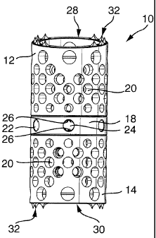
Figure 1 shows a preferred embodiment of a spinal implant in its compressed
state which in
its entirety is designated as 10. One can see an upper outer sleeve 12 and a
lower outer sleeve 14
3
CA 02455339 2006-10-24
which, with their front surfaces 16 (see Figure 2) facing each other, rest
against a supporting ring
18. In addition, one can see that outer sleeves 12 and 14 have perforations 20
through which bone
tissue can grow into the inside of the spinal implant 10.
Supporting ring 18 has radially running openings 22, through the inside cross-
section 24 of
which portions of teeth 26 can be seen. Also, the two outer sleeves 12 and 14
have outwardly
oriented front surfaces 28 and 30 which have spinous extensions 32 that
project in an axial
3a
CA 02455339 2003-10-30
direction. These spinous extensions 32 penetrate the contact surfaces of the
neighboring
vertebrae and there anchor the two outer sleeves 12 and 14.
Figures 2 and 3 show an upper inner sleeve 34 and a lower inner sleeve 36
which are
screwed into the associated upper outer sleeve 12 and lower outer sleeve 14.
In addition, the
figures show two grub screws 38 which can be screwed into an associated tapped
hole 40 of
outer sleeves 12 and 14, which affixes outer sleeves 12 and 14 to inner
sleeves 34 and 36.
Tapped holes 40 for grub screws 38 are located in the immediate vicinity of
front surfaces 16 of
outer sleeves 12 and 14. Also visible is a locking element 42 by means of
which the two inner
sleeves 34 and 36 can be attached to each other.
One can clearly see that the plane of front surface 28 is inclined at an angle
a to the
orthogonal plane relative to longitudinal axis 44. This makes it possible to
optimally adjust
spinal implant 10 to the position of the neighboring vertebrae or to correct
the position of said
vertebrae. For this purpose, an outer sleeve 12 or 14 having a front surface
28 or 30, respectively,
with the inclination required is selected. It can also be seen that sleeves
12, 14, 34, and 36 and
supporting ring 18 and locking element 42 are disposed coaxially with respect
to one another and
with respect to longitudinal axis 44.
Figures 4 and 5 are enlarged representations of the two outer sleeves 12 and
14, except
that the inside thread 46 disposed on the inner circumference is only
schematically shown or
suggested. This inside thread 46 is, e.g., a fine thread with a pitch of 1 mm
and a diameter of
22 mm, and is designed as a right-hand thread.
Figures 4 and 5 also show that a relatively large oblong perforation 48 is
provided in the
walls of outer sleeves 12 and 14, through which perforation, after extension,
bone tissue can be
filled into the inside of spinal implant 10 .
Figure 6 shows an enlarged perspective view of inner sleeves 34 and 36 which,
along
their outer circumference, have an outside thread 50 which again is only
schematically shown or
suggested. Inner sleeves 34 and 36 also have perforations 52. On one of their
front surfaces 54,
inner sleeves 34 and 36 have a flange 56 which projects radially outwardly and
which, on its
outwardly oriented front surface, has teeth 26 which are preferably designed
in the form of
beveled teeth. In the longitudinal section shown in Figure 7, these beveled
teeth can be clearly
seen.
It can also be seen that flange 56 has a shoulder 58 which projects radially
inwardly and
onto which detents 60 of a locking element 62 can latch. Such a locking
element 62 is shown in
Figure 9. This locking element 62 is also designed in the form of a sleeve and
has, on its surface
lying oppositely to detents 60, a radially projecting retention flange 64
which comes to lie behind
the associated shoulder 58 of the other inner sleeve 36. The detents are
disposed on elastic tabs
4
CA 02455339 2004-11-16
68, thus making it possible to deflect them radiallytoward the inside. In this
manner, it is possible to
connect the two inner sleeves 34 and 36 to each other.
Figure 8 shows supporting ring 18 on which the two inner sleeves 34 and 36
with teeth 26 are
seated. For this purpose, supporting ring 18 should have a shoulder 66 which
projects radially inwardly
and which is subdivided into a total of six segments. Shoulder 66 is disposed
in such a way as to
intersect with openings 22, with the diameter of openings 22 being greater
than the thickness of shoulder
66. This has the effect that part of teeth 26 project into the inside cross-
section of openings 22 when inner
sleeves 34 and 36 are resting on shoulder 66. Teeth 26 can thus be accessed
from the outside through
opening 22, as shown in Figures 1 and 2.
Figure 10 finally shows a tool 70 which has an oblong shape and a star-shaped
cross-section. Tool
70 also has teeth 72 which, together with teeth 26, form a bevel tooth gear.
The tool can be disposed on a
rigid rod or on a flexible shaft, thus making it easily possible for tool 70
to reach even difficult-to-access
areas and to extend spinal implant 10.
5