Sélection de la langue

Search

Sommaire du brevet 2455339 

Énoncé de désistement de responsabilité concernant l'information provenant de tiers

Une partie des informations de ce site Web a été fournie par des sources externes. Le gouvernement du Canada n'assume aucune responsabilité concernant la précision, l'actualité ou la fiabilité des informations fournies par les sources externes. Les utilisateurs qui désirent employer cette information devraient consulter directement la source des informations. Le contenu fourni par les sources externes n'est pas assujetti aux exigences sur les langues officielles, la protection des renseignements personnels et l'accessibilité.

Disponibilité de l'Abrégé et des Revendications

L'apparition de différences dans le texte et l'image des Revendications et de l'Abrégé dépend du moment auquel le document est publié. Les textes des Revendications et de l'Abrégé sont affichés :

  • lorsque la demande peut être examinée par le public;
  • lorsque le brevet est émis (délivrance).
(12) Brevet: (11) CA 2455339
(54) Titre français: IMPLANT VERTEBRAL EXTENSIBLE ET OUTIL DE D'EXTENSION
(54) Titre anglais: EXTENDABLE SPINAL IMPLANT AND EXTENSION TOOL
Statut: Réputé périmé
Données bibliographiques
(51) Classification internationale des brevets (CIB):
  • A61F 2/44 (2006.01)
  • A61F 2/46 (2006.01)
(72) Inventeurs :
  • SCHAFER, BERND (Suisse)
  • TRAUTWEIN, THILO (Allemagne)
  • LILJENQUIST, ULF (Allemagne)
(73) Titulaires :
  • DEPUY SPINE SARL (Suisse)
(71) Demandeurs :
  • SCHAFER, BERND (Suisse)
(74) Agent: SIM & MCBURNEY
(74) Co-agent:
(45) Délivré: 2009-01-13
(86) Date de dépôt PCT: 2003-01-30
(87) Mise à la disponibilité du public: 2003-09-12
Requête d'examen: 2003-11-18
Licence disponible: S.O.
(25) Langue des documents déposés: Anglais

Traité de coopération en matière de brevets (PCT): Oui
(86) Numéro de la demande PCT: PCT/EP2003/000932
(87) Numéro de publication internationale PCT: WO2003/073964
(85) Entrée nationale: 2003-10-30

(30) Données de priorité de la demande:
Numéro de la demande Pays / territoire Date
102 10 214.7 Allemagne 2002-03-02

Abrégés

Abrégé français

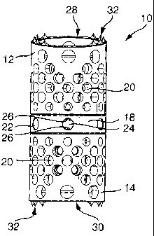
L'invention concerne un implant vertébral capable de distraction, comportant une première douille extérieure, une deuxième douille extérieure orientée coaxialement par rapport à la première, et un élément d'entraînement intérieur vissé à au moins une des douilles extérieures. L'élément d'entraînement intérieur présente un premier filetage, par ex. un filetage extérieur, et la douille extérieure vissée à l'élément d'entraînement présente un deuxième filetage correspondant au premier, par ex. un filetage intérieur. Par ailleurs, l'élément d'entraînement intérieur s'appuie sur une bague support, et l'élément d'entraînement peut être entraîné sur son côté frontal orienté vers la bague support.


Abrégé anglais


The subject matter of the present invention relates to an extendable spinal
implant with a first outer
sleeve and a second outer sleeve coaxially disposed thereto and an inside
drive element which is
connected by means of screws to at least one of the outer sleeves, with the
inside drive element
comprising a first thread, e.g., an outside thread, and with the outer sleeve
that is connected by means of
screws to the drive element comprising a second thread, e.g. an inside thread,
that fits on the outside
thread, with the inside drive element resting on a supporting ring and with
the drive element being able to
be driven in the area of its front surface that faces the supporting ring.

Revendications

Note : Les revendications sont présentées dans la langue officielle dans laquelle elles ont été soumises.


Claims

1. An extendable spinal implant with a first outer sleeve and a second outer
sleeve coaxially
disposed thereto and an inside drive element which is connected by means of
screws to at least one of the
outer sleeve, with said inside drive element having a first thread, and with
the outer sleeve that is
connected by means of screws to the drive element having a second thread, that
fits on an outside thread,
wherein the inside drive element is seated on a supporting ring and that the
drive element can be driven in
the area of its front surface that faces the supporting ring.


2. The spinal implant as claimed in claim 1, wherein the drive element
comprises two inner
sleeves.


3. The spinal implant as claimed in claim 2, wherein each inner sleeve is
screwed into an outer
sleeve.


4. The spinal implant as claimed in claim 2 or 3, wherein the inner sleeves
are spaced a certain
distance apart by means of the supporting ring.


5. The spinal implant as claimed in any one of claims 2 to 4, wherein the
front surface of the
drive element or the inner sleeve has teeth.


6. The spinal implant as claimed in any one of claims 1 to 5, wherein the
supporting ring has at
least one radial opening.


7. The spinal implant as claimed in any one of claims 2 to 6, wherein the
supporting ring has a
shoulder which projects radially inwardly and which serves as a support for
the front surface of the inner
sleeve.


8. The spinal implant as claimed in claims 6 or 7, wherein the opening and the
shoulder intersect
with each other.


9. The spinal implant as claimed in claim 8, wherein the diameter of the
opening is greater than
the thickness of the shoulder.


6


10. The spinal implant as claimed in claims 5 or 6, wherein the teeth project
into the inside cross-
section of the opening.


11. The spinal implant as claimed in any one of claims 3 to 10, wherein each
of the inner sleeves
and the outer sleeves have a right-hand thread or a left-hand thread.


12. The spinal implant as claimed in any one of claims 3 to 10, wherein the
surfaces of the inner
sleeves and/or the outer sleeves have perforations.


13. The spinal implant as claimed in claim 12, wherein at least one of the
perforations of at least
one sleeve is large enough so as to make it possible to fill the sleeve with
tissue substance.


14. The spinal implant as claimed in any one of claims 3 to 13, wherein one of
the outer sleeves
has an outwardly projecting front surface which is positioned at an angle (a)
to the orthogonal plane
relative to the longitudinal axis.


15. The spinal implant as claimed in any one of claims 3 to 14, wherein the
outer sleeve and the
associated inner sleeve can be affixed to each other by means of a grub screw
that can be radially
screwed into the outer sleeve.


16. The spinal implant as claimed in any one of claims 2 to 15, wherein the
two inner sleeves are
maintained on the supporting ring by means of a locking element, with said
locking element having
outwardly projecting detents which extend behind inwardly projecting shoulders
that are disposed on the
inner sleeve.


17. The spinal implant as claimed in any one of claims 1 to 16 wherein said
first thread is an
outside thread.


18. The spinal implant as claimed in any one of claims 1 to 17 wherein said
second thread is an
inside thread.


19. A tool for adjusting an extendable spinal implant as claimed in any one of
claims 1 to 18,
wherein the tool is designed in the shape of a rod and has a star-shaped cross-
section.


7

Description

Note : Les descriptions sont présentées dans la langue officielle dans laquelle elles ont été soumises.


CA 02455339 2003-10-30

Title: EXTENDABLE SPINAL IMPLANT AND EXTENSION TOOL
Description
The subject matter of the present invention concerns an extendable spinal
implant with a
first outer sleeve and, coaxially disposed thereon, a second outer sleeve and
an inside drive
element which is partially connected by means of screws to at least one of the
outer sleeves, with
the inside drive element having a first screw thread, e.g., an outside screw
thread, and the outer
sleeve that is screwed to the drive element having a second screw thread,
e.g., an inside screw
thread, that fits on the outside screw thread.
Such spinal implants serve as intervertebral implants to replace individual
vertebrae, as is
known, e.g., from U.S. Patent No. 4,657,550. In this prior-art intervertebral
implant, a thread bolt
is screwed into each end of a threaded sleeve, with the two front surfaces of
the thread bolts
facing away from each other meshing with the buttressing bases which abut the
vertebrae to be
buttressed. When the threaded sleeve is turned by means of a radially
insertable pin or by means
of a hooked wrench, the two thread bolts having a right-hand and a left-hand
thread are screwed
out of or into said threaded sleeve. The disadvantage is that the tool used
for turning the threaded
sleeve has to be removed and reinserted after it has made a certain turn,
e.g., after a quarter turn,
which is difficult or even impossible in a great number of surgical
interventions.
Thus, the problem to be solved by the present invention is to make available a
spinal
implant, in particular an intervertebral implant, that can be more universally
used and
considerably more easily handled during implantation.
This problem is solved according to the present invention by means of an
extendable
spinal implant in which the inside drive element is resting on a supporting
ring and the drive
element can be driven in the area of the front surface that faces the
supporting ring.
The inside drive element preferably has two inner sleeves. According to an
advanced
embodiment, each inner sleeve is screwed into an outer sleeve. The front
surfaces of the inner
sleeves that face each other preferably are resting on a supporting ring which
spaces said sleeves
a certain distance apart from each other.
In the spinal implant according to the present invention as claimed in Claim
1, the two
outer portions are formed by an outer sleeve, which has the advantage that,
compared to the prior
art mentioned above, said outer sleeve supports the spinal implant over a
larger supporting area
on the facing vertebra. Thus, buttressing bases are not required. In addition,
having the drive, in
particular a bevel drive, located on the front surface makes it possible to
avoid having to reinsert
the tool after it has made a certain turn since the tool, in contrast to prior
art, does not engage the
circumference but the front surface of the drive element.

1


CA 02455339 2003-10-30

the inner sleeve does not have to be turned to a certain position in order to
be able, e.g., to
remove or reinsert the tool.
The inner sleeves and the outer sleeves preferably have a right-hand thread or
a left-hand
thread. This has the significant advantage that the same components can be
used for the two
inner sleeves; this also applies to the outer sleeves if no special adjustment
to the position or
shape of the vertebrae is necessary. Furthermore, only one tool or one machine
setting is required
to produce the inside thread on the outer sleeve and to produce the outside
thread on the inner
sleeve.
To ensure an optimum union between the implant and the surrounding tissue, the
surface
of the inner sleeves and/or the outer sleeves has perforations through which
the growth of bone
tissue is facilitated. In addition, the perforations also reduce the overall
weight of the implant.
According to an advanced embodiment, at least one of the perforations of at
least one of
the sleeves is of a size that makes it possible to fill or to supplement the
sleeve with tissue
substance. After the spinal implant according to the present invention has
been extended, this
implant first must be filled with additional tissue substance which can easily
be inserted via
relatively large perforations. These relatively large perforations are also
located in the surface of
at least one of the sleeves, with the perforation preferably having an
elongated or a long oval
shape.
To ensure an optimum fit of the spinal implant to the curvature of the spinal
column, at
least one of the outer sleeves has a front surface which projects outwardly
and which is located at
an angle to the orthogonal plane relative to the longitudinal axis. Thus, this
outside surface does
not run perpendicular to the longitudinal axis of the spinal implant but is
inclined relative to this
plane. Since the system is a modular system, there are a number of different
outer sleeves to
choose from, which sleeves have outside surfaces with different angles of
inclination or surfaces
with no inclination.
These outside surfaces preferably have spinous extensions so that an optimum
support on
the abutting vertebra is ensured.
To fix the final extended position, the outer sleeve and the associated inner
sleeve can be
affixed to each other by means of a grub screw that can be radially screwed
into the outer sleeve.
This ensures that the spinal implant does not independently change its
position, in particular that
it does not contract.
To connect the two inner sleeves to each other, a locking element is provided,
which
locking element maintains the two inner sleeves on the supporting ring, with
the locking element
having outwardly projecting detents, in particular on elastic tabs, which
extend behind inwardly
projecting shoulders provided on the inner sleeve. An additional advantage of
this locking
element is that the entire spinal implant can be modularly constructed and can
be assembled

2


CA 02455339 2007-10-11

immediately prior to implantation. No tools are required since the locking
element needs to be
merely pushed into an inner sleeve and be extended behind the shoulders of the
adjacent inner
sleeve.
The subject matter of the present invention also relates to a tool for
adjusting the
extendable spinal implant, said tool being designed in the shape of a rod and
having a star-shaped
cross-section. In addition, the distal end of the tool can be slightly
conically tapered similar to a
beveled gear. The tool can be easily inserted into and turned in the
supporting ring. In addition,
the tool can be disposed on a flexible shaft so that the implant can be used
and extended even if it
is difficult to access the implant.
In accordance with an aspect of the present invention, there is provided an
extendable
spinal implant with a first outer sleeve and a second outer sleeve coaxially
disposed thereto and
an inside drive element which is connected by means of screws to at least one
of the outer sleeve,
with said inside drive element having a first thread, and with the outer
sleeve that is connected by
means of screws to the drive element having a second thread, that fits on an
outside thread,
wherein the inside drive element is seated on a supporting ring and that the
drive element can be
driven in the area of its front surface that faces the supporting ring.
Other advantages, characteristics, and details of the invention follow from
the description
below which also includes details of an especially preferred embodiment which
is described with
reference to the drawing. The characteristics illustrated in the drawing and
mentioned in the claims
and in the description may be essential to the invention either separately or
in any combination with
each other.
The drawing shows the following figures:
Figure 1: a perspective view of an embodiment of the extendable spinal implant
according to
the present invention;
Figure 2: the spinal implant according to Figure 1 in an extended position;
Figure 3: the spinal implant according to Figure 1 in an exposition [sic;
exploded] view;
Figure 4: an enlarged representation of a perspective view of the upper outer
sleeve
according to Figure 3;
Figure 5: an enlarged representation of a perspective view of the lower outer
sleeve
according to Figure 3;
Figure 6: an enlarged representation of a perspective view of an inner sleeve;
Figure 7: a longitudinal section through the inner sleeve;
Figure 8: an enlarged representation of a perspective view of a supporting
ring;
Figure 9: an enlarged representation of a perspective view of a locking
element, and
Figure 10: a perspective view of a tool for extending the spinal implant.
Figure 1 shows a preferred embodiment of a spinal implant in its compressed
state which in
its entirety is designated as 10. One can see an upper outer sleeve 12 and a
lower outer sleeve 14
3


CA 02455339 2006-10-24

which, with their front surfaces 16 (see Figure 2) facing each other, rest
against a supporting ring
18. In addition, one can see that outer sleeves 12 and 14 have perforations 20
through which bone
tissue can grow into the inside of the spinal implant 10.
Supporting ring 18 has radially running openings 22, through the inside cross-
section 24 of
which portions of teeth 26 can be seen. Also, the two outer sleeves 12 and 14
have outwardly
oriented front surfaces 28 and 30 which have spinous extensions 32 that
project in an axial

3a


CA 02455339 2003-10-30

direction. These spinous extensions 32 penetrate the contact surfaces of the
neighboring
vertebrae and there anchor the two outer sleeves 12 and 14.
Figures 2 and 3 show an upper inner sleeve 34 and a lower inner sleeve 36
which are
screwed into the associated upper outer sleeve 12 and lower outer sleeve 14.
In addition, the
figures show two grub screws 38 which can be screwed into an associated tapped
hole 40 of
outer sleeves 12 and 14, which affixes outer sleeves 12 and 14 to inner
sleeves 34 and 36.
Tapped holes 40 for grub screws 38 are located in the immediate vicinity of
front surfaces 16 of
outer sleeves 12 and 14. Also visible is a locking element 42 by means of
which the two inner
sleeves 34 and 36 can be attached to each other.
One can clearly see that the plane of front surface 28 is inclined at an angle
a to the
orthogonal plane relative to longitudinal axis 44. This makes it possible to
optimally adjust
spinal implant 10 to the position of the neighboring vertebrae or to correct
the position of said
vertebrae. For this purpose, an outer sleeve 12 or 14 having a front surface
28 or 30, respectively,
with the inclination required is selected. It can also be seen that sleeves
12, 14, 34, and 36 and
supporting ring 18 and locking element 42 are disposed coaxially with respect
to one another and
with respect to longitudinal axis 44.
Figures 4 and 5 are enlarged representations of the two outer sleeves 12 and
14, except
that the inside thread 46 disposed on the inner circumference is only
schematically shown or
suggested. This inside thread 46 is, e.g., a fine thread with a pitch of 1 mm
and a diameter of
22 mm, and is designed as a right-hand thread.
Figures 4 and 5 also show that a relatively large oblong perforation 48 is
provided in the
walls of outer sleeves 12 and 14, through which perforation, after extension,
bone tissue can be
filled into the inside of spinal implant 10 .
Figure 6 shows an enlarged perspective view of inner sleeves 34 and 36 which,
along
their outer circumference, have an outside thread 50 which again is only
schematically shown or
suggested. Inner sleeves 34 and 36 also have perforations 52. On one of their
front surfaces 54,
inner sleeves 34 and 36 have a flange 56 which projects radially outwardly and
which, on its
outwardly oriented front surface, has teeth 26 which are preferably designed
in the form of
beveled teeth. In the longitudinal section shown in Figure 7, these beveled
teeth can be clearly
seen.
It can also be seen that flange 56 has a shoulder 58 which projects radially
inwardly and
onto which detents 60 of a locking element 62 can latch. Such a locking
element 62 is shown in
Figure 9. This locking element 62 is also designed in the form of a sleeve and
has, on its surface
lying oppositely to detents 60, a radially projecting retention flange 64
which comes to lie behind
the associated shoulder 58 of the other inner sleeve 36. The detents are
disposed on elastic tabs

4


CA 02455339 2004-11-16

68, thus making it possible to deflect them radiallytoward the inside. In this
manner, it is possible to
connect the two inner sleeves 34 and 36 to each other.
Figure 8 shows supporting ring 18 on which the two inner sleeves 34 and 36
with teeth 26 are
seated. For this purpose, supporting ring 18 should have a shoulder 66 which
projects radially inwardly
and which is subdivided into a total of six segments. Shoulder 66 is disposed
in such a way as to
intersect with openings 22, with the diameter of openings 22 being greater
than the thickness of shoulder
66. This has the effect that part of teeth 26 project into the inside cross-
section of openings 22 when inner
sleeves 34 and 36 are resting on shoulder 66. Teeth 26 can thus be accessed
from the outside through
opening 22, as shown in Figures 1 and 2.
Figure 10 finally shows a tool 70 which has an oblong shape and a star-shaped
cross-section. Tool
70 also has teeth 72 which, together with teeth 26, form a bevel tooth gear.
The tool can be disposed on a
rigid rod or on a flexible shaft, thus making it easily possible for tool 70
to reach even difficult-to-access
areas and to extend spinal implant 10.

5

Dessin représentatif
Une figure unique qui représente un dessin illustrant l'invention.
États administratifs

Pour une meilleure compréhension de l'état de la demande ou brevet qui figure sur cette page, la rubrique Mise en garde , et les descriptions de Brevet , États administratifs , Taxes périodiques et Historique des paiements devraient être consultées.

États administratifs

Titre Date
Date de délivrance prévu 2009-01-13
(86) Date de dépôt PCT 2003-01-30
(87) Date de publication PCT 2003-09-12
(85) Entrée nationale 2003-10-30
Requête d'examen 2003-11-18
(45) Délivré 2009-01-13
Réputé périmé 2016-02-01

Historique d'abandonnement

Il n'y a pas d'historique d'abandonnement

Historique des paiements

Type de taxes Anniversaire Échéance Montant payé Date payée
Enregistrement de documents 100,00 $ 2003-10-30
Le dépôt d'une demande de brevet 150,00 $ 2003-10-30
Requête d'examen 200,00 $ 2003-11-18
Enregistrement de documents 100,00 $ 2004-10-26
Taxe de maintien en état - Demande - nouvelle loi 2 2005-01-31 100,00 $ 2004-12-13
Taxe de maintien en état - Demande - nouvelle loi 3 2006-01-30 100,00 $ 2005-12-13
Taxe de maintien en état - Demande - nouvelle loi 4 2007-01-30 100,00 $ 2006-12-29
Taxe de maintien en état - Demande - nouvelle loi 5 2008-01-30 200,00 $ 2007-12-27
Enregistrement de documents 100,00 $ 2008-06-17
Taxe finale 300,00 $ 2008-10-24
Taxe de maintien en état - Demande - nouvelle loi 6 2009-01-30 200,00 $ 2008-12-18
Taxe de maintien en état - brevet - nouvelle loi 7 2010-02-01 200,00 $ 2009-12-18
Taxe de maintien en état - brevet - nouvelle loi 8 2011-01-31 200,00 $ 2011-01-17
Taxe de maintien en état - brevet - nouvelle loi 9 2012-01-30 200,00 $ 2012-01-05
Taxe de maintien en état - brevet - nouvelle loi 10 2013-01-30 250,00 $ 2012-12-13
Taxe de maintien en état - brevet - nouvelle loi 11 2014-01-30 250,00 $ 2013-12-11
Titulaires au dossier

Les titulaires actuels et antérieures au dossier sont affichés en ordre alphabétique.

Titulaires actuels au dossier
DEPUY SPINE SARL
Titulaires antérieures au dossier
LILJENQUIST, ULF
MICROMED ORTHO AG
SCHAFER, BERND
TRAUTWEIN, THILO
Les propriétaires antérieurs qui ne figurent pas dans la liste des « Propriétaires au dossier » apparaîtront dans d'autres documents au dossier.
Documents

Pour visionner les fichiers sélectionnés, entrer le code reCAPTCHA :


Pour visualiser une image, cliquer sur un lien dans la colonne description du document. Pour télécharger l'image (les images), cliquer l'une ou plusieurs cases à cocher dans la première colonne et ensuite cliquer sur le bouton "Télécharger sélection en format PDF (archive Zip)" ou le bouton "Télécharger sélection (en un fichier PDF fusionné)".

Liste des documents de brevet publiés et non publiés sur la BDBC .

Si vous avez des difficultés à accéder au contenu, veuillez communiquer avec le Centre de services à la clientèle au 1-866-997-1936, ou envoyer un courriel au Centre de service à la clientèle de l'OPIC.


Description du
Document 
Date
(yyyy-mm-dd) 
Nombre de pages   Taille de l'image (Ko) 
Abrégé 2003-10-30 1 16
Revendications 2003-10-30 2 91
Description 2003-10-30 5 284
Dessins 2003-10-30 10 89
Dessins représentatifs 2003-10-30 1 9
Page couverture 2004-03-25 1 39
Abrégé 2004-11-16 1 16
Description 2004-11-16 5 282
Revendications 2004-11-16 2 75
Description 2006-10-24 6 299
Revendications 2006-10-24 2 75
Dessins 2006-10-24 4 79
Description 2007-10-11 6 298
Revendications 2007-10-11 2 74
Dessins représentatifs 2008-12-23 1 12
Page couverture 2008-12-23 1 44
PCT 2003-10-30 5 198
Cession 2003-10-30 3 121
Correspondance 2003-11-20 1 32
Poursuite-Amendment 2003-11-18 1 53
Cession 2004-02-20 3 97
Poursuite-Amendment 2004-08-06 1 42
Poursuite-Amendment 2006-05-08 2 51
Taxes 2006-12-29 1 52
Cession 2008-06-17 8 240
Cession 2004-10-26 2 75
Correspondance 2004-10-26 2 100
Cession 2003-10-30 4 168
Poursuite-Amendment 2004-11-16 6 156
Taxes 2004-12-13 1 53
Taxes 2005-12-13 1 51
Poursuite-Amendment 2006-10-24 10 283
Poursuite-Amendment 2007-05-22 2 44
Poursuite-Amendment 2007-10-11 4 172
Correspondance 2008-10-24 1 58