Language selection

Search

Patent 2467808 Summary

Third-party information liability

Some of the information on this Web page has been provided by external sources. The Government of Canada is not responsible for the accuracy, reliability or currency of the information supplied by external sources. Users wishing to rely upon this information should consult directly with the source of the information. Content provided by external sources is not subject to official languages, privacy and accessibility requirements.

Claims and Abstract availability

Any discrepancies in the text and image of the Claims and Abstract are due to differing posting times. Text of the Claims and Abstract are posted:

  • At the time the application is open to public inspection;
  • At the time of issue of the patent (grant).
(12) Patent: (11) CA 2467808
(54) English Title: INSTALLATION FOR PROGRAMMABLE PYROTECHNIC SHOT FIRING
(54) French Title: INSTALLATION DE TIRS PYROTECHNIQUES PROGRAMMABLES
Status: Deemed expired
Bibliographic Data
(51) International Patent Classification (IPC):
  • F42D 1/05 (2006.01)
(72) Inventors :
  • BERNARD, THIERRY (France)
(73) Owners :
  • CHEMICAL HOLDINGS INTERNATIONAL LTD. (Mauritius)
(71) Applicants :
  • CHEMICAL HOLDINGS INTERNATIONAL LTD. (Mauritius)
(74) Agent: RIDOUT & MAYBEE LLP
(74) Associate agent:
(45) Issued: 2009-12-22
(86) PCT Filing Date: 2002-11-14
(87) Open to Public Inspection: 2003-05-30
Examination requested: 2007-10-17
Availability of licence: N/A
(25) Language of filing: English

Patent Cooperation Treaty (PCT): Yes
(86) PCT Filing Number: PCT/FR2002/003891
(87) International Publication Number: WO2003/044451
(85) National Entry: 2004-05-19

(30) Application Priority Data:
Application No. Country/Territory Date
01/14916 France 2001-11-19

Abstracts

English Abstract


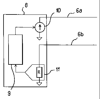
Programmable pyrotechnical firing installation comprising a programming and
firing
control unit (8), a programming and control line comprising two conductor
wires (6a,
6b) and a plurality of electronic detonators (4) mounted in parallel on this
two-wire
line, characterised in that the programming unit (8) comprises means (9, 10)
for
establishing a continuous voltage between the two wires (6a, 6b), means (9,
10) for
producing pulses of this voltage so as to form coded signals, and means (11,
9) for
reading the current variations existing on the two-wire line, wherein every
detonator
comprises an electronic module (12) that has means (14, 17) suitable for
producing, in
response to certain of the coded signals of the programming unit (8), current
pulses in
the two-wire line (6a, 6b) for forming coded signals.


French Abstract

Installation de tirs pyrotechniques programmables comportant une unité (8) de programmation et de commande des tirs, une ligne de programmation et de commande comportant deux fils (6a, 6b) conducteurs et une pluralité de détonateurs électroniques (12) montés en parallèle sur cette ligne bifilaire, caractérisée en ce que l'unité de programmation (8) comporte des moyens (9, 10) d'établissement d'une tension continue entre les deux fils (6a, 6b), des moyens (9, 10) pour engendrer des impulsions de cette tension afin de former des signaux codés, et des moyens (11, 9) de lecture des variations de courant existant sur la ligne bifilaire tandis que chaque détonateur comporte un module électronique (12) possédant des moyens (14, 17) aptes à engendrer, en réponse à certains des signaux codés de l'unité (8) de programmation, des impulsions de courant dans la ligne bifilaire (6a, 6b) pour former des signaux codés.

Claims

Note: Claims are shown in the official language in which they were submitted.


7


CLAIMS


1. A programmable pyrotechnical firing installation comprising a programming
and
firing control unit (8), a programming and control line comprising two
conductor
wires (6a, 6b) and a plurality of electronic detonators (4) mounted in
parallel on
this two-wire line, characterised in that the programming unit (8) comprises
means (9, 10) for establishing a continuous voltage between the two wires (6a,

6b), means (9, 10) for producing pulses of this voltage so as to form coded
signals
and means (11, 9) for reading the current variations existing on the two-wire
line
and in that every detonator comprises an electronic module (12) that has means

(14, 17) suitable for producing, in response to certain of the coded signals
of the
programming unit (8), current pulses in the two-wire line (6a, 6b) for forming

coded signals.


2. A firing installation according to claim 1, characterised in that every
electronic
detonator module (12) comprises a switch (18) of the two-wire line (6a, 6b),
which normally is open and is closed in response to a signal emitted by the
programming unit (8).


Description

Note: Descriptions are shown in the official language in which they were submitted.


CA 02467808 2009-02-04

1
INSTALLATION FOR PROGRAMMABLE PYROTECHNIC SHOT FIRING

In mines and quarries the breaking of rocks is typically carried out by means
of
explosives.

A firing program consists of making a plurality of drill-holes in the rock,
which are
filled with explosives with, for every drill-hole, a detonator that permits
the firing.
Some of these detonators are electronically controlled, which makes it
possible to
program the setting off of the explosions according to a predetermined firing
plan.
The execution of a firing plan consists, therefore, after having arranged all
the
detonators in the drill-holes that have been made and connecting them to a
control
unit, of identifying every detonator by a serial number and applying to it a
delay
time which will determine the ignition of the charge in relation to a general
firing
signal.

The present invention relates to such a programmable pyrotechnical firing
installation, in which all the detonators are connected to the control unit by
wires.
Conventionally, an electronic detonator comprises a pyrotechnical percussion
cap,
an energy reserve, an electronic pilot and two electrical conductors that
connect the
electronic pilot to a firing line which runs over the ground from a central
programming and control unit. The electronic pilot comprises an on-board
microprocessor by means of which communication can be established between the
detonator and the central unit. The microprocessor is programmed or program-
mable so as to be able to receive requests issued in the firing line by the
central
unit and to respond to these requests either in the direction of the central
unit or in
the direction of the energy reserve, which it will release with a specific
time delay


CA 02467808 2004-05-19
2
when the firing order has been received from the central unit. The programming
of
the on-board microprocessor in the electronic pilot of the detonator can be
carried
out a priori before its positioning in the firing field or, as is the case for
the
invention, a posteriori after it has been put into position. The firing line
on the
ground also serves to provide the electrical energy required for filling the
energy
reserve, which takes place just before the firing in order to comply with the
safety
requirements that demand that the detonators must be inactive up to the last
moment.

It must be borne in mind that a firing line may have a length of about a
kilometre.
For this reason, with the current installations it is relatively simple to
transmit
from the control unit signals to the address of every detonator, however far
this
may be removed from the control unit, since the required energy to be provided
for these. signals so that they will reach their target is controlled totally
from the
control unit. On the other hand, a detonator has very little on-board energy
and if
one wants it to be able to respond to the central unit, it will be noted that
the
limited power of the signals which it emits suffers a strong attenuation that
may
make them inaudible by the central. unit if the detonator-emitter is far away
from
same on the firing line.

The present invention provides a solution to this bi-directional communication
problem between a central unit and each one of the detonators of a firing
line, a
simple and economical solution.

To this end, the invention relates to a programmable pyrotechnical firing
installation comprising a programming and control unit for the firing, a
programming and control line comprising two conductor wires and a plurality of
electronic detonators mounted in parallel on this two-wire line, wherein the
programming unit comprises means for establishing a continuous voltage between


CA 02467808 2004-05-19
3
the two wires, means for producing pulses of this voltage so as to form coded
signals and means for reading the current variations existing on the two-wire
line
and wherein every detonator comprises an electronic module that, in response
to
certain of the coded signals of the programming unit corresponding to requests
from same, can produce current pulses in thetwo-wire line for forming coded
signals.

In other words, when a detonator, whatever its position on the firing line,
must
respond to a request of the central unit, it will produce in the filar firing
line excess
current peaks, for example by closing the line on a calibrated resistor within
a
given time and this in dependence on a pulses program corresponding to a code
generated by the on-board microprocessor, which excess current peaks are
immediately detectable by the central unit, which by means of a resistor will
convert them into a modulated voltage that can be interpreted by its micro-
processor, this forming the response of the detonator in que-stion to the
request of
this central unit.

Other characteristics and advantages of the invention will be noted from the
description given below by way of non-limitative example, of an exemplified
embodiment.

Reference will be made to the attached drawings, wherein:

- Figure 1 is a diagram illustrating a pyrotechnical firing installation,

- Figure 2 illustrates diagrammatically a central programming and control unit
of the installation,

- Figure 3 is a functional diagram of that part of the electronic pilot of
every
detonator involved in the dialogue with the central programming and control
unit.


CA 02467808 2004-05-19
4

ti
To carry out a firing program, holes 1 are drilled in a rock 2 from, for
example, the
ground 3. In each of these drill-holes 1, detonators 4 and explosive charges 5
are
placed, every detonator 4 being connected to firing line 6 on the ground by
conductors 7. A central programming and con,trol unit is shown at 8, connected
to
the firing line 6.

This unit 8, see figure 2, comprises a microprocessor 9 which acts on a device
10
for the supply of a continuous voltage between the two wires 6a, 6b of the
line 6
and which permits, inserting into this continuous voltage drop sequences so as
to
form slots corresponding to any type of binary code of a signal. Furthermore,
the
central unit 8 is provided with a device 11 for converting into voltage the
current
circulating on the line 6a, 6b in order to produce variations of this current
that can
be understood by the microprocessor 9.

The electronic pilot 12 of the detonator illustrated diagrammatically and
partially
in figure 3, comprises a voltage regulator 13, the input of which is connected
to
the line 6a, and the output to an on-board microprocessor 14, in order to form
a
power supply of this microprocessor 14 increased by a capacitor 15 that
permits
smoothing the drops in voltage in the line 6. This pilot 12 also comprises a
circuit
16,for detecting codes carried by the line 6, the input of which is also
connected to
the line 6a and the outiput of which is directed towards the microprocessor
14.
Between the lines 6a and 6b the electronic pilot 12 has a voltage-drawing
circuit
17, for example a transistor and a resistor, controlled by the microprocessor
14.
Finally, the microprocessor 14 controls a switch 18 of the line 6a, in a
manner as
will be explained below.


CA 02467808 2004-05-19

Each one of the detonators 4 is connected to the two-wire line 6a, 6b parallel
to same
at the point A, B (figure 3). In reality, four wires 19, 20, 21, 22 come from
this
electronic pilot 12, which form the conductors 7 of figure 1. The wires 19 and
20
permit connecting the pilot to the wires 6a and 6b of the firing line. The
line 6a has a
section 23 inside the pilot 12, which comprises the switch 18 and which comes
out of
the pilot by way of the line 21 which becomes 6a at the level of the ground.
In the
same manner the line 6b has a section 24 inside the pilot, which by way of the
conductor 22 comes out of the drill-hole to form the wire 6b of the firing
line at the
level of the ground. At the time when the detonators are positioned in the
drill-holes,
the switch 18 is open. The electronic pilots are connected the one following
the other.
Understood under this mounting method is that the first detonator connected to
the unit
8 is mounted in series on the line 6a, 6b when the switch 18 is open. When the
switch
18 is closed, this detonator is mounted in parallel with the next one on the
line 6a, 6b.
When the firing line has been realised, the central unit 8 establishes a
voltage of, for
example, 24 or 48 volt at the terminals of the conductors 6a, 6b. This
voltage,
regulated by the device 13, constitutes the power supply of the processor 14
as well as
the charge of the capacitor 15. By cutting this voltage by means of the device
10, the
microprocessor 9 of the central unit 8 transmits to the pilot 12 a serial
number
recorded by the microprocessor 14, and a certain delay time. The operating
sequence
of the microprocessor 9 may then comprise a request (a binary signal on the
voltage of
the line 6) to which the microprocessor 14 will respond by acting on the
current-drawing circuit 17 to create excess voltage peaks which, converted by
the
device 11, will be assimilated as a response to the request by the
microprocessor 9.
The last order transmitted by the microprocessor 9 to the on board
microprocessor 14
will be to close the switch 18. At this moment, the pilot


CA 02467808 2004-05-19
6
{
of the next detonator is in the same state with regard to the central unit 8
as the
preceding pilot and the programming sequence can recommence.

When all the detonators have been programmed in this manner, the firing
installation is ready to operate. The microprocessor 9 may comprise in its
program
.other stages and other requests concerning the detonators. It will then
transmit a
general order to all the detonators to proceed with the charging of the energy
reserve, not illustrated in the figures, possibly followed- by a verification
of the
state of this reserve, and will finally transmit to all the detonators a
firing signal.

Representative Drawing
A single figure which represents the drawing illustrating the invention.
Administrative Status

For a clearer understanding of the status of the application/patent presented on this page, the site Disclaimer , as well as the definitions for Patent , Administrative Status , Maintenance Fee  and Payment History  should be consulted.

Administrative Status

Title Date
Forecasted Issue Date 2009-12-22
(86) PCT Filing Date 2002-11-14
(87) PCT Publication Date 2003-05-30
(85) National Entry 2004-05-19
Examination Requested 2007-10-17
(45) Issued 2009-12-22
Deemed Expired 2019-11-14

Abandonment History

There is no abandonment history.

Payment History

Fee Type Anniversary Year Due Date Amount Paid Paid Date
Application Fee $400.00 2004-05-19
Maintenance Fee - Application - New Act 2 2004-11-15 $100.00 2004-09-27
Registration of a document - section 124 $100.00 2004-10-12
Maintenance Fee - Application - New Act 3 2005-11-14 $100.00 2005-10-14
Maintenance Fee - Application - New Act 4 2006-11-14 $100.00 2006-09-26
Maintenance Fee - Application - New Act 5 2007-11-14 $200.00 2007-10-02
Request for Examination $800.00 2007-10-17
Maintenance Fee - Application - New Act 6 2008-11-14 $200.00 2008-11-14
Maintenance Fee - Application - New Act 7 2009-11-16 $200.00 2009-09-17
Final Fee $300.00 2009-09-23
Maintenance Fee - Patent - New Act 8 2010-11-15 $200.00 2010-10-25
Maintenance Fee - Patent - New Act 9 2011-11-14 $200.00 2011-10-13
Maintenance Fee - Patent - New Act 10 2012-11-14 $250.00 2012-10-10
Maintenance Fee - Patent - New Act 11 2013-11-14 $250.00 2013-10-09
Maintenance Fee - Patent - New Act 12 2014-11-14 $250.00 2014-10-22
Maintenance Fee - Patent - New Act 13 2015-11-16 $250.00 2015-11-09
Maintenance Fee - Patent - New Act 14 2016-11-14 $250.00 2016-08-22
Maintenance Fee - Patent - New Act 15 2017-11-14 $450.00 2017-10-27
Maintenance Fee - Patent - New Act 16 2018-11-14 $450.00 2018-10-16
Owners on Record

Note: Records showing the ownership history in alphabetical order.

Current Owners on Record
CHEMICAL HOLDINGS INTERNATIONAL LTD.
Past Owners on Record
BERNARD, THIERRY
Past Owners that do not appear in the "Owners on Record" listing will appear in other documentation within the application.
Documents

To view selected files, please enter reCAPTCHA code :


To view images, click a link in the Document Description column. To download the documents, select one or more checkboxes in the first column and then click the "Download Selected in PDF format (Zip Archive)" or the "Download Selected as Single PDF" button.

List of published and non-published patent-specific documents on the CPD .

If you have any difficulty accessing content, you can call the Client Service Centre at 1-866-997-1936 or send them an e-mail at CIPO Client Service Centre.


Document
Description 
Date
(yyyy-mm-dd) 
Number of pages   Size of Image (KB) 
Cover Page 2004-09-29 1 40
Abstract 2004-05-19 1 24
Claims 2004-05-19 1 29
Drawings 2004-05-19 1 34
Description 2004-05-19 6 257
Representative Drawing 2004-05-19 1 10
Description 2009-02-04 6 251
Abstract 2009-12-01 1 24
Representative Drawing 2009-12-04 1 4
Cover Page 2009-12-04 1 38
Prosecution-Amendment 2008-01-02 1 27
Correspondence 2004-09-28 1 27
Fees 2004-09-27 1 30
Fees 2005-10-14 1 28
Assignment 2004-10-12 2 59
PCT 2004-05-19 23 953
Assignment 2004-05-19 5 134
Fees 2006-09-26 1 30
Prosecution-Amendment 2007-10-17 1 27
Fees 2007-10-02 1 38
Correspondence 2009-01-15 1 25
Fees 2008-11-14 1 35
Correspondence 2009-02-04 2 78
Correspondence 2009-09-23 1 35
Fees 2009-09-17 1 36