Note: Descriptions are shown in the official language in which they were submitted.
CA 02517835 2005-08-26
WO 2004/080651 PCT/SE2004/000283
Z
i'~ C~1~II~3DING D2A.CHINE
'.The present invention relates to a grinding machine, and more
:specifically to a back-carried grinding machine for grinding
c~-r honing drill bits .
Drill bits are subjected to great deal of wear must be
a and
well-honed in order to ock effectively. Bits that are
drill r
~~oorly sharpened only impair the efficacy of rock
do not
~o dri_lling, bLlt also causethe drill string and the drilling
:Tics to be subj ecaed to great deal of stress and rain and
a st
also wear.
consequently, there is a great need for grinding, honing,
c:~ril1 bits at regular intervals. There exist to this end
special serni-aui~omatic grinding machines for grinding the
button bits and also for
grinding down the steel
included in
vhe drill bit, at the same time. Transportable grinding ma-
chines that enable the button bit to be ground at the site
2o t~ahere drilling takes lace are also available commercially.
p
'These machines may be semi-automatic machines or manually
operated ma.c:hines and are exclusively of the type that use
gr finding cusps .
2s l~ccordingly, an obj ect of the present invention is to provide
a grinding machine of the aforesaid kind which can funct_Lon
at least semi-automatically and which can be used to recreate
both a spherica:L and ballistic button bit and which c:a.n be
mounted on a drilling rig or on a separate readily transport-
30 <able arrangernent .
'rhi_s object i~; achieved with a button bit grinding machine
comprising a grinding unit that includes a motor unit which
CA 02517835 2005-08-26
WO 2004/080651 PCT/SE2004/000283
2
drives a spindle to which a grinding wheel is fitted for
:rotation by said spindle and therewith sharpen or hone a
button bit in the drill bit crown. According to the inven-
vion, the grinding unit together with the grinding wheel are
s adapted to be swung forwards and backwards about a vertical
;;ha:ft i~hat coincides generally with the geometric axis of the
button bit.
The in;rention will now be described in more detail with ref-
~o erence to a. non--limiting exemplifying embodiment thereof and
<also with :refer~snce to the accompanying drawings, in which
7Hic~. 1 is a side view showing the grinding machine in an
adjusted setting in which the grinding wheel is centred
around a button bit on a drill bit crown; Fig. 2 illustrates
a5 a grinding unit in a grinding intermediate position~ although
;said unit is shown distanced from the drill bit crown for the
;sake of cla:=it.y; Fic~. 3 illustrates the grinding unit in a
first turning position, although corresponding to the view of
:,ig-. 2 ir_ other respects; and Fig. 4 illustrates the grinding
2o un.i_t irz a second turning position.
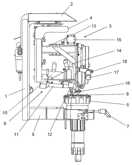
'L'he gr:i_nding machine illustrated in the accompanying drawings
.i_s intended to be mounted on a drilling rig and includes a
carrier frame 1 intended for fastening to a drilling rig, not
a5 shown. The frame 1 has an upper, outwardly projecting carrier
arm 2 which carries the grinding arrangement 3 of said grind-
.i_ng machine via a bracket structure 4 that can be displaced
:in the hor:L~ontal plane. The grinding arrangement 3 ca.n be
:raised and lowered in the bracket structure 4, i.e. ca.n be
so displaced, in the vertical plane. The frame 1 also inc.Ludes a
holder ai:m 5 which is located beneath the grinding arrange-
ment and adapi~ed to hold firmly a drill bii~ crown 6. The
drill bit crown 6 can be readily fitted to and locked in the
ho~_der arrn 5, with the aid of a locking lever 7. The crown 6
CA 02517835 2005-08-26
WO 2004/080651 PCT/SE2004/000283
3
:includes a number of button bits 8. The number of button bits
8 included, and their size and placement on the crown 6, may
vary. The cro~m may also be locked obliquely in the holder
arm 5, to enable correct grinding of the peripheral button
hits 8a in the drill bit crown 6.
')?he gra_nding arrangement 3 includes a grinding unit 9 whir_h,
:in turn, incJludes a motor 10, a spindle 11 and a grinding
naheel 12 carried on the end of the spindle 11. The grinding
>o unit 9 is fitted so that the spindle will slope slightly ire
:relation to the horizontal plane, wherein the grinding wheel
rotates ~~bout said spindle. The grinding wheel 12 is of a
:Lnown ty~>e and is provided with a diamond coating and may be
designed for grinding spherical or ballistic button bits. The
grinding unit 9 is carried by an arm 13 on the grinding ar-
rangement anal can be swung about a generally vertical shaft
:14 with the aid of a pivot cylinder 15 which is adapted to
;swing the grinding unit 9 forwards and backwards between the
positions shown in Figs . 3 and 4, i . a . with a pendulum move-
~o meet of about 180°, preferably slightly greater than 180°..
The
:haft 14 i~~ arranged so that an extension of the shaft will
1?ass through the centre of the grinding wheel 12 and so that
<~.s the grinding unit 9 swings forwards and backwards, the
grinding wheel will move about a point which corresponds to
2s -she top of one of the button bits 8 when the grinding ar-
rangement 3 is correctly adjusted. The geometric axis about
~~ah~_ch the grinding unit 9 moves forwards and backwards is a
generally vertical axis which coincides with the geometric
centre axis of the button bit 8 when the grinding arrangement
so :3 has been ~corrf~ctly adjusted in relation to the button bit
8. The grinding unit 9 thus moves forwards and backwards in a
1?endulum movement in the horizontal plane, so as to be able
vo grind or hone a button bit 8 that extends generally verti-
cally on t:he grinding occasion concerned.
CA 02517835 2005-08-26
WO 2004/080651 PCT/SE2004/000283
4
;~djustrnent to the setting of the grinding arrangement 3 is
achieved with the aid of a centring body 16 which can be
placed and centred over a button bit 8, as shown in Fig. 1.
Tn this position, the centring body is located in the a<~ten-
;~ion of thE: shaft 14 and on the geometric a~>i s about which
-Mlle grinding unit 9 is intended to swing. Where the grinding
arrangement: 3 has been centred over a button bit in this way,
she ar:rangement 3 is locked against movement in the hor:Lzon-
~o va7_ plane and can then be solely raised and lowered. Subse-
c~uent to being centred, the grinding arrangement 3 must first
he raised ~~o that the centring body 16 can be swung to one
;side, to the position shown in Figs. 2-4, and so that the
grinding disc can be lowered down onto the drill bit crown 6
a5 arid agains t the button bit 8 for grinding said bit . Loe:k_ing
o f the grinding arrangement in the horizontal plane is the
;subject of a ,separate patent application filed at the same
mime as the instant application.
20 The grinding arrangement 3 includes an operating lever 17
with which said arrangement can be moved to the correct posi-
vion in the horizontal plane for adjusting the setting of the
arrangement wii~h the aid of the centring cup 16. The arrange-
ment 3 may also include in connection with the lever 17 a
25 c~ontro7_ device 18 with which movement of said arrangement 3
:in the horizontal plane can be locked/released. The lever is
<also used for raising and lowering the grinding arrangement.
There may also be provided in connection with the lever 17
activating means with which the grinding arrangement 3 can be
so activated, i.e. with which the motor 10 can be activated for
:rotation <>f the grinding wheel 12, and also activation of the
lpivot cylinder 15 for causing pendulum movement of the grind-
ing un_Lt J.. This activation may also take place automatir_ally
CA 02517835 2005-08-26
WO 2004/080651 PCT/SE2004/000283
when the arrangement 3 has been brought to its correct posi-
rian .
')?he grinding unit 9 is thus able to achieve automatic grind-
s :inn of the button bits 8 in a drill bit crown 6, subsequent
'.o the grinding unit 9 having been adj usted manually by the
operator in re:Lation to the bit to be ground. The cylinder 15
:is adapted t o pivot the grinding unit 9 forwards and back-
5~aards about. the centre of the button bit 8 concerned, for
~o :instance for a pre-set period of the time normally taken to
grind or bane a button bit. The pendulum movement of the
grinding unit will preferably cover at least 180°, preferably
;lightly more than 180°, in order for the bit to be ground
crorrectly.
'L'he grinding wheels 1~ used in the grinding machine according
-~a the invention are of the same type as those used in the
c_~r_indirsg machines mentioned in the introductian for worlcshop
use, and ~~amprise diamond-coated grinding wheels that are
~o availal.~le in both spherical and ballistic designs~ said
grinding wheels being chosen in accordance with the type of
button bit to be ground. These wheels have the form of a
hu7_ley or caller that includes two ends which have a :Larger
diameter than the intermediate part and which have a spheri-
25 c~a7_ or ballistic recess to give the button b~_t to be ground
vhe desired shape.
'1?he inventive grinding machine is, as before mentioned,
suitably maunted. on a drilling rig and is suitably supplied
30 'aith power, electrical, pneumatic or hydraulic power, and
water from the drilling rig. Alternatively, the grinding
machine may, c>f course, be mounted on an own transportable
device, for instance a wagon or carriage, although this will
Then require an additional electrical, pneumatic or hydraulic
CA 02517835 2005-08-26
WO 2004/080651 PCT/SE2004/000283
6
;supply means for driving the grinding machine. The inventive
grinding machine may also, of course, be used conveniently in
a permanent: structure in a workshop environment.