Sélection de la langue

Search

Sommaire du brevet 2517835 

Énoncé de désistement de responsabilité concernant l'information provenant de tiers

Une partie des informations de ce site Web a été fournie par des sources externes. Le gouvernement du Canada n'assume aucune responsabilité concernant la précision, l'actualité ou la fiabilité des informations fournies par les sources externes. Les utilisateurs qui désirent employer cette information devraient consulter directement la source des informations. Le contenu fourni par les sources externes n'est pas assujetti aux exigences sur les langues officielles, la protection des renseignements personnels et l'accessibilité.

Disponibilité de l'Abrégé et des Revendications

L'apparition de différences dans le texte et l'image des Revendications et de l'Abrégé dépend du moment auquel le document est publié. Les textes des Revendications et de l'Abrégé sont affichés :

  • lorsque la demande peut être examinée par le public;
  • lorsque le brevet est émis (délivrance).
(12) Demande de brevet: (11) CA 2517835
(54) Titre français: RECTIFIEUSE
(54) Titre anglais: A GRINDING MACHINE.
Statut: Réputée abandonnée et au-delà du délai pour le rétablissement - en attente de la réponse à l’avis de communication rejetée
Données bibliographiques
Abrégés

Abrégé français

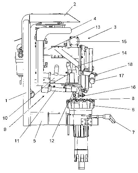
L'invention concerne une rectifieuse (3) servant à rectifier des trépans (6), laquelle rectifieuse comporte une unité de rectification (9) qui intègre un bloc moteur (10) et une broche (11) entraînée par ledit moteur et portant une meule (12) prévue pour effectuer une rotation par l'intermédiaire de la broche (11) et pour rectifier une pastille (8) dans le trépan (6). Selon la présente invention, ladite unité de rectification (9) est adaptée, conjointement avec la meule (12), pour pivoter en avant et en arrière autour d'un arbre vertical coïncidant de façon générale avec l'axe géométrique de la pastille (8).


Abrégé anglais


A grinding machine (3) for grinding drill bits (6), comprising a grinding unit
(9) which includes a motor unit (10) and a spindle (11) which is driven by
said motor and which carries a grinding wheel (12) for rotation by the spindle
(11) and for grinding a button bit (8) in the drill bit (6), wherein the
grinding unit (9) together with the grinding wheel (12) is adapted to swing
forwards and backwards about a vertical shaft which coincides generally with
the geometric axis of the button bit (8).

Revendications

Note : Les revendications sont présentées dans la langue officielle dans laquelle elles ont été soumises.


7
CLAIMS
1. A grinding machine (3) for grinding drill bits (6),
comprising a grinding unit (9) which includes a motor unit
(10) and a spindle (11) which is driven by said motor and
which carries a grinding wheel (12) for rotation by the spin-
dle (11) and for grinding a button bit (8) in the drill bit
(6), characterised in that the grinding unit (9) together
with the grinding wheel (12) is adapted to swing forwards and
backwards about a vertical shaft which coincides generally
with the geometric axis of the button bit (8).
2. A grinding machine according to Claim 1, character-
ised in that the grinding unit (9) is adapted to swing for-
wards and backwards through an angle that covers about 180°
3. A grinding machine according to Claim 1 or Claim 2,
characterised in that the grinding unit (9) is adapted to
swing forwards and backwards in a plane close to the horizon-
tal plane.
4. A grinding machine according to any one of the pre-
ceding Claims, characterised in that the grinding unit (9)
can be moved in the horizontal plane so as to enable said
unit to be centred over a button bit (8) in a drill bit (6).
5. A grinding machine according to Claim 4, character-
ised in that the grinding machine includes a centring cup
(16) for centring the grinding unit (9) over the button bit
(8) in said drill bit.
6.~A grinding machine according to Claim 5, character-
ised in that subsequent to centring of the grinding unit (9),

8
said unit can be locked in the horizontal plane so as to be
movable solely in the vertical plane.
7. A grinding machine according to any one of the pre-
ceding Claims, characterised in that the grinding machine is
mounted on a drilling rig.
8. A grinding machine according to any one of Claims 1
6, characterised in that the grinding machine is mounted for
transportation on a wagon or carriage.
9. A grinding machine according to any one of Claims 1
6, characterised in that the grinding machine is fixedly
mounted in a workshop environment.

Description

Note : Les descriptions sont présentées dans la langue officielle dans laquelle elles ont été soumises.

CA 02517835 2005-08-26
WO 2004/080651 PCT/SE2004/000283
Z
i'~ C~1~II~3DING D2A.CHINE
'.The present invention relates to a grinding machine, and more
:specifically to a back-carried grinding machine for grinding
c~-r honing drill bits .
Drill bits are subjected to great deal of wear must be
a and
well-honed in order to ock effectively. Bits that are
drill r
~~oorly sharpened only impair the efficacy of rock
do not
~o dri_lling, bLlt also causethe drill string and the drilling
:Tics to be subj ecaed to great deal of stress and rain and
a st
also wear.
consequently, there is a great need for grinding, honing,
c:~ril1 bits at regular intervals. There exist to this end
special serni-aui~omatic grinding machines for grinding the
button bits and also for
grinding down the steel
included in
vhe drill bit, at the same time. Transportable grinding ma-
chines that enable the button bit to be ground at the site
2o t~ahere drilling takes lace are also available commercially.
p
'These machines may be semi-automatic machines or manually
operated ma.c:hines and are exclusively of the type that use
gr finding cusps .
2s l~ccordingly, an obj ect of the present invention is to provide
a grinding machine of the aforesaid kind which can funct_Lon
at least semi-automatically and which can be used to recreate
both a spherica:L and ballistic button bit and which c:a.n be
mounted on a drilling rig or on a separate readily transport-
30 <able arrangernent .
'rhi_s object i~; achieved with a button bit grinding machine
comprising a grinding unit that includes a motor unit which

CA 02517835 2005-08-26
WO 2004/080651 PCT/SE2004/000283
2
drives a spindle to which a grinding wheel is fitted for
:rotation by said spindle and therewith sharpen or hone a
button bit in the drill bit crown. According to the inven-
vion, the grinding unit together with the grinding wheel are
s adapted to be swung forwards and backwards about a vertical
;;ha:ft i~hat coincides generally with the geometric axis of the
button bit.
The in;rention will now be described in more detail with ref-
~o erence to a. non--limiting exemplifying embodiment thereof and
<also with :refer~snce to the accompanying drawings, in which
7Hic~. 1 is a side view showing the grinding machine in an
adjusted setting in which the grinding wheel is centred
around a button bit on a drill bit crown; Fig. 2 illustrates
a5 a grinding unit in a grinding intermediate position~ although
;said unit is shown distanced from the drill bit crown for the
;sake of cla:=it.y; Fic~. 3 illustrates the grinding unit in a
first turning position, although corresponding to the view of
:,ig-. 2 ir_ other respects; and Fig. 4 illustrates the grinding
2o un.i_t irz a second turning position.
'L'he gr:i_nding machine illustrated in the accompanying drawings
.i_s intended to be mounted on a drilling rig and includes a
carrier frame 1 intended for fastening to a drilling rig, not
a5 shown. The frame 1 has an upper, outwardly projecting carrier
arm 2 which carries the grinding arrangement 3 of said grind-
.i_ng machine via a bracket structure 4 that can be displaced
:in the hor:L~ontal plane. The grinding arrangement 3 ca.n be
:raised and lowered in the bracket structure 4, i.e. ca.n be
so displaced, in the vertical plane. The frame 1 also inc.Ludes a
holder ai:m 5 which is located beneath the grinding arrange-
ment and adapi~ed to hold firmly a drill bii~ crown 6. The
drill bit crown 6 can be readily fitted to and locked in the
ho~_der arrn 5, with the aid of a locking lever 7. The crown 6

CA 02517835 2005-08-26
WO 2004/080651 PCT/SE2004/000283
3
:includes a number of button bits 8. The number of button bits
8 included, and their size and placement on the crown 6, may
vary. The cro~m may also be locked obliquely in the holder
arm 5, to enable correct grinding of the peripheral button
hits 8a in the drill bit crown 6.
')?he gra_nding arrangement 3 includes a grinding unit 9 whir_h,
:in turn, incJludes a motor 10, a spindle 11 and a grinding
naheel 12 carried on the end of the spindle 11. The grinding
>o unit 9 is fitted so that the spindle will slope slightly ire
:relation to the horizontal plane, wherein the grinding wheel
rotates ~~bout said spindle. The grinding wheel 12 is of a
:Lnown ty~>e and is provided with a diamond coating and may be
designed for grinding spherical or ballistic button bits. The
grinding unit 9 is carried by an arm 13 on the grinding ar-
rangement anal can be swung about a generally vertical shaft
:14 with the aid of a pivot cylinder 15 which is adapted to
;swing the grinding unit 9 forwards and backwards between the
positions shown in Figs . 3 and 4, i . a . with a pendulum move-
~o meet of about 180°, preferably slightly greater than 180°..
The
:haft 14 i~~ arranged so that an extension of the shaft will
1?ass through the centre of the grinding wheel 12 and so that
<~.s the grinding unit 9 swings forwards and backwards, the
grinding wheel will move about a point which corresponds to
2s -she top of one of the button bits 8 when the grinding ar-
rangement 3 is correctly adjusted. The geometric axis about
~~ah~_ch the grinding unit 9 moves forwards and backwards is a
generally vertical axis which coincides with the geometric
centre axis of the button bit 8 when the grinding arrangement
so :3 has been ~corrf~ctly adjusted in relation to the button bit
8. The grinding unit 9 thus moves forwards and backwards in a
1?endulum movement in the horizontal plane, so as to be able
vo grind or hone a button bit 8 that extends generally verti-
cally on t:he grinding occasion concerned.

CA 02517835 2005-08-26
WO 2004/080651 PCT/SE2004/000283
4
;~djustrnent to the setting of the grinding arrangement 3 is
achieved with the aid of a centring body 16 which can be
placed and centred over a button bit 8, as shown in Fig. 1.
Tn this position, the centring body is located in the a<~ten-
;~ion of thE: shaft 14 and on the geometric a~>i s about which
-Mlle grinding unit 9 is intended to swing. Where the grinding
arrangement: 3 has been centred over a button bit in this way,
she ar:rangement 3 is locked against movement in the hor:Lzon-
~o va7_ plane and can then be solely raised and lowered. Subse-
c~uent to being centred, the grinding arrangement 3 must first
he raised ~~o that the centring body 16 can be swung to one
;side, to the position shown in Figs. 2-4, and so that the
grinding disc can be lowered down onto the drill bit crown 6
a5 arid agains t the button bit 8 for grinding said bit . Loe:k_ing
o f the grinding arrangement in the horizontal plane is the
;subject of a ,separate patent application filed at the same
mime as the instant application.
20 The grinding arrangement 3 includes an operating lever 17
with which said arrangement can be moved to the correct posi-
vion in the horizontal plane for adjusting the setting of the
arrangement wii~h the aid of the centring cup 16. The arrange-
ment 3 may also include in connection with the lever 17 a
25 c~ontro7_ device 18 with which movement of said arrangement 3
:in the horizontal plane can be locked/released. The lever is
<also used for raising and lowering the grinding arrangement.
There may also be provided in connection with the lever 17
activating means with which the grinding arrangement 3 can be
so activated, i.e. with which the motor 10 can be activated for
:rotation <>f the grinding wheel 12, and also activation of the
lpivot cylinder 15 for causing pendulum movement of the grind-
ing un_Lt J.. This activation may also take place automatir_ally

CA 02517835 2005-08-26
WO 2004/080651 PCT/SE2004/000283
when the arrangement 3 has been brought to its correct posi-
rian .
')?he grinding unit 9 is thus able to achieve automatic grind-
s :inn of the button bits 8 in a drill bit crown 6, subsequent
'.o the grinding unit 9 having been adj usted manually by the
operator in re:Lation to the bit to be ground. The cylinder 15
:is adapted t o pivot the grinding unit 9 forwards and back-
5~aards about. the centre of the button bit 8 concerned, for
~o :instance for a pre-set period of the time normally taken to
grind or bane a button bit. The pendulum movement of the
grinding unit will preferably cover at least 180°, preferably
;lightly more than 180°, in order for the bit to be ground
crorrectly.
'L'he grinding wheels 1~ used in the grinding machine according
-~a the invention are of the same type as those used in the
c_~r_indirsg machines mentioned in the introductian for worlcshop
use, and ~~amprise diamond-coated grinding wheels that are
~o availal.~le in both spherical and ballistic designs~ said
grinding wheels being chosen in accordance with the type of
button bit to be ground. These wheels have the form of a
hu7_ley or caller that includes two ends which have a :Larger
diameter than the intermediate part and which have a spheri-
25 c~a7_ or ballistic recess to give the button b~_t to be ground
vhe desired shape.
'1?he inventive grinding machine is, as before mentioned,
suitably maunted. on a drilling rig and is suitably supplied
30 'aith power, electrical, pneumatic or hydraulic power, and
water from the drilling rig. Alternatively, the grinding
machine may, c>f course, be mounted on an own transportable
device, for instance a wagon or carriage, although this will
Then require an additional electrical, pneumatic or hydraulic

CA 02517835 2005-08-26
WO 2004/080651 PCT/SE2004/000283
6
;supply means for driving the grinding machine. The inventive
grinding machine may also, of course, be used conveniently in
a permanent: structure in a workshop environment.

Dessin représentatif
Une figure unique qui représente un dessin illustrant l'invention.
États administratifs

2024-08-01 : Dans le cadre de la transition vers les Brevets de nouvelle génération (BNG), la base de données sur les brevets canadiens (BDBC) contient désormais un Historique d'événement plus détaillé, qui reproduit le Journal des événements de notre nouvelle solution interne.

Veuillez noter que les événements débutant par « Inactive : » se réfèrent à des événements qui ne sont plus utilisés dans notre nouvelle solution interne.

Pour une meilleure compréhension de l'état de la demande ou brevet qui figure sur cette page, la rubrique Mise en garde , et les descriptions de Brevet , Historique d'événement , Taxes périodiques et Historique des paiements devraient être consultées.

Historique d'événement

Description Date
Demande non rétablie avant l'échéance 2010-03-02
Le délai pour l'annulation est expiré 2010-03-02
Inactive : Abandon.-RE+surtaxe impayées-Corr envoyée 2009-03-02
Réputée abandonnée - omission de répondre à un avis sur les taxes pour le maintien en état 2009-03-02
Inactive : IPRP reçu 2007-04-23
Lettre envoyée 2006-01-13
Inactive : Transfert individuel 2005-12-06
Inactive : Lettre de courtoisie - Preuve 2005-11-01
Inactive : Page couverture publiée 2005-10-28
Inactive : Notice - Entrée phase nat. - Pas de RE 2005-10-26
Demande reçue - PCT 2005-10-13
Exigences pour l'entrée dans la phase nationale - jugée conforme 2005-08-26
Demande publiée (accessible au public) 2004-09-23

Historique d'abandonnement

Date d'abandonnement Raison Date de rétablissement
2009-03-02

Taxes périodiques

Le dernier paiement a été reçu le 2008-02-12

Avis : Si le paiement en totalité n'a pas été reçu au plus tard à la date indiquée, une taxe supplémentaire peut être imposée, soit une des taxes suivantes :

  • taxe de rétablissement ;
  • taxe pour paiement en souffrance ; ou
  • taxe additionnelle pour le renversement d'une péremption réputée.

Les taxes sur les brevets sont ajustées au 1er janvier de chaque année. Les montants ci-dessus sont les montants actuels s'ils sont reçus au plus tard le 31 décembre de l'année en cours.
Veuillez vous référer à la page web des taxes sur les brevets de l'OPIC pour voir tous les montants actuels des taxes.

Historique des taxes

Type de taxes Anniversaire Échéance Date payée
Taxe nationale de base - générale 2005-08-26
Enregistrement d'un document 2005-08-26
TM (demande, 2e anniv.) - générale 02 2006-03-02 2006-02-16
TM (demande, 3e anniv.) - générale 03 2007-03-02 2007-02-26
TM (demande, 4e anniv.) - générale 04 2008-03-03 2008-02-12
Titulaires au dossier

Les titulaires actuels et antérieures au dossier sont affichés en ordre alphabétique.

Titulaires actuels au dossier
ATLAS COPCO SECOROC AB
Titulaires antérieures au dossier
HANS LINDGREN
Les propriétaires antérieurs qui ne figurent pas dans la liste des « Propriétaires au dossier » apparaîtront dans d'autres documents au dossier.
Documents

Pour visionner les fichiers sélectionnés, entrer le code reCAPTCHA :


Pour visualiser une image, cliquer sur un lien dans la colonne description du document. Pour télécharger l'image (les images), cliquer l'une ou plusieurs cases à cocher dans la première colonne et ensuite cliquer sur le bouton "Télécharger sélection en format PDF (archive Zip)" ou le bouton "Télécharger sélection (en un fichier PDF fusionné)".

Liste des documents de brevet publiés et non publiés sur la BDBC .

Si vous avez des difficultés à accéder au contenu, veuillez communiquer avec le Centre de services à la clientèle au 1-866-997-1936, ou envoyer un courriel au Centre de service à la clientèle de l'OPIC.


Description du
Document 
Date
(aaaa-mm-jj) 
Nombre de pages   Taille de l'image (Ko) 
Description 2005-08-25 6 251
Dessins 2005-08-25 4 116
Abrégé 2005-08-25 2 70
Dessin représentatif 2005-08-25 1 29
Revendications 2005-08-25 2 56
Revendications 2005-08-26 2 55
Rappel de taxe de maintien due 2005-11-02 1 109
Avis d'entree dans la phase nationale 2005-10-25 1 192
Courtoisie - Certificat d'enregistrement (document(s) connexe(s)) 2006-01-12 1 104
Rappel - requête d'examen 2008-11-03 1 127
Courtoisie - Lettre d'abandon (taxe de maintien en état) 2009-04-26 1 172
Courtoisie - Lettre d'abandon (requête d'examen) 2009-06-07 1 165
PCT 2005-08-25 4 144
Correspondance 2005-10-25 1 25
PCT 2005-08-25 7 310