Language selection

Search

Patent 2529006 Summary

Third-party information liability

Some of the information on this Web page has been provided by external sources. The Government of Canada is not responsible for the accuracy, reliability or currency of the information supplied by external sources. Users wishing to rely upon this information should consult directly with the source of the information. Content provided by external sources is not subject to official languages, privacy and accessibility requirements.

Claims and Abstract availability

Any discrepancies in the text and image of the Claims and Abstract are due to differing posting times. Text of the Claims and Abstract are posted:

  • At the time the application is open to public inspection;
  • At the time of issue of the patent (grant).
(12) Patent: (11) CA 2529006
(54) English Title: CARRIER PLATE HOLDING AN ABRADING ELEMENT AND ABRADING PLATE
(54) French Title: PLATEAU PORTEUR SUPPORTANT UN ELEMENT ABRASIF ET PLAQUE ABRASIVE
Status: Granted
Bibliographic Data
(51) International Patent Classification (IPC):
  • B24D 7/06 (2006.01)
  • B24B 7/18 (2006.01)
(72) Inventors :
  • THYSELL, HAKAN (Sweden)
  • THYSELL, KARL (Sweden)
  • OLSEN, LARS (Sweden)
(73) Owners :
  • HUSQVARNA AB (Sweden)
(71) Applicants :
  • HTC SWEDEN AB (Sweden)
(74) Agent: RIDOUT & MAYBEE LLP
(74) Associate agent:
(45) Issued: 2011-07-26
(86) PCT Filing Date: 2004-06-10
(87) Open to Public Inspection: 2004-12-16
Examination requested: 2009-03-10
Availability of licence: N/A
(25) Language of filing: English

Patent Cooperation Treaty (PCT): Yes
(86) PCT Filing Number: PCT/SE2004/000905
(87) International Publication Number: WO2004/108352
(85) National Entry: 2005-12-09

(30) Application Priority Data:
Application No. Country/Territory Date
0301709-2 Sweden 2003-06-11

Abstracts

English Abstract


The invention concerns a carrier plate (2) holding an abrading element, for
detachable mounting on a rotatably mounted abrading plate (1) driven during
use, for abrading stone or concrete floors, which carrier plate (2) has sides
(2a, 2b) which form an acute angle with each other. The sides (2a, 2b) have
flanges (2a1, 2b1) which are formed for surrounding engagement with a shoulder
(1a) arranged on the abrading plate (1) so that the carrier plate (2) can be
fixed on the abrading plate (1) with an engagement based on form and friction.


French Abstract

L'invention concerne un plateau porteur (2) supportant un élément abrasif, destiné au montage amovible d'une plaque abrasive montée de façon rotative (1) entraînée en fonctionnement, en vue d'abraser des sols en pierre ou en béton, le plateau porteur (2) comportant des côtés (2a, 2b) formant ensemble un angle aigu. Ces côtés (2a, 2b) possèdent des ailes (2a1, 2b1) qui sont formées de manière à se coupler autour d'un épaulement (1a) placé sur la plaque abrasive (1) de manière que le plateau porteur (2) puisse être fixé sur la plaque abrasive (1) par couplage basé sur la forme et la frottement.

Claims

Note: Claims are shown in the official language in which they were submitted.


4

CLAIMS


1. A carrier plate detachably mounted on a rotatably mounted abrading plate
that
is driven during use to abrade stone or concrete floors, the carrier plate
comprising:

a top surface having a first edge shorter than an opposing second edge;
an abrading element affixed to the top surface;
a first side arranged on a third edge of the top surface;
a second side arranged on a fourth edge of the top surface, the fourth
edge opposing the third edge, the first and second sides forming an acute
angle; and
two flanges, each flange arranged on a respective one of the first and
second sides, the two flanges being provided to engage a shoulder arranged on
the abrading plate by surrounding said shoulder to affix the carrier plate on
the
abrading plate with an engagement based on form and friction, said flanges
being angled inwards towards a centerline of the carrier plate and downwards
towards the abrading plate.

2. An apparatus for abrading stone or concrete floors comprising:
an abrading plate provided to be rotatably driven during use;
a carrier plate detachably mounted on the abrading plate and including
an abrading element;
a first side provided to form an acute angle with respect to a second
side, the acute angle pointing towards a center of the abrading plate, a
radius
from the center of the abrading plate dividing the each of the acute angle and

the carrier plate into equal parts; and

two flanges, each flange arranged on a respective one of the first and
second sides, the two flanges being provided to engage a shoulder arranged on
the abrading plate by surrounding said shoulder to axially affix the carrier
plate on the abrading plate within a circumference of the abrading plate, the
carrier plate being affixed with an engagement based on form and friction, the

two flanges being angled inward toward a centerline of the carrier plate.


3. A carrier plate detachably mounted on a rotatably mounted abrading plate
driven during use to abrade stone or concrete floors, the carrier plate
comprising:
a top surface having a first edge shorter than an opposing second edge;
an abrading element affixed to the top surface;
a first side arranged on a third edge of the top surface;
a second side arranged on a fourth edge of the top surface, the fourth
edge opposing the third edge, the first and second sides forming an acute
angle; and
two flanges, each flange arranged on a respective one of the first and
second sides, the two flanges being provided to engage a shoulder arranged on
the abrading plate by surrounding said shoulder to affix the carrier plate can
on
the abrading plate with an engagement based on form and friction, the flanges
being rounded about an axis parallel to the respective sides to contact
complementary-shaped surfaces on the shoulder of the abrading plate.

4. The abrading apparatus according to claim 2, wherein the two flanges are
rounded about an axis parallel to the respective sides to contact
complementary-shaped surfaces on the shoulder of the abrading plate.

Description

Note: Descriptions are shown in the official language in which they were submitted.


CA 02529006 2010-07-07

WO 2004/108352 PCT/SE2004/000905
1
CARRIER PLATE HOLDING AN ABRADING ELEMENT
AND ABRADING PLATE
Technical field
The present invention concerns a carrier plate holding an abrading element and
an
abrading plate device according to the preamble of the respective independent
claims.

Technical background
A machine, preferably for abrading stone and concrete floors, is known for
example
from PCT/SE93/00865. The abrading element, fixed on a carrier plate which in
turn
is detachably mounted on the abrading plate, must be considered a consumable.
Changing the abrading element is labour-intensive and time-consuming, and
adversely affects the production time of the abrading machine.

Examples of known devices for detachable mounting of abrading elements on
abrading discs are shown in DE-1 127 745, US-1,470,957 and US-5,076,023.
Summary of the invention
The object of the present invention is to produce a device of the type
described
initially which facilitates the replacement of the abrading element and hence
contributes to a better working environment and increased production.

Thus a carrier plate holding an abrading element is produced, for detachable
mounting on a rotatably mounted abrading plate driven during use, for abrading
stone or concrete floors, which carrier plate has sides which form an acute
angle with
each other. The carrier plate is characterised in that the sides have flanges
which are
designed for surrounding engagement with a shoulder arranged on the abrading
plate
so that the carrier plate can be fixed on the abrading plate with an
engagement based
on form and friction.


CA 02529006 2005-12-09
WO 2004/108352 PCT/SE2004/000905
2
An abrading plate is also produced for abrading stone or concrete floors,
which
abrading plate is rotatably mounted and driven during use and formed for
detachable
mounting of at least one carrier plate holding an abrading element. The
abrading
plate is characterised by a shoulder arranged on the abrading plate which has
side
edges forming an acute angle with each other and which is designed for
engagement
with flanges arranged on the carrier plate so that the carrier plate by
surrounding
engagement can be fixed on the abrading plate in an engagement based on form
and
friction.

The invention thus achieves the simplified mounting of carrier plates on the
abrading
plate, which mounting is also quick to both establish and release.

As a particular characteristic of the invention shows, because of the acute
angle
between the undercut groove and naturally also between the corresponding edges
shaped complementary to the groove on the carrier plate, the engagement
between
the groove and the carrier plate edges can be established and released very
quickly.
Carrier plates according to the invention also have the advantage that they
can be
produced at relatively low cost.
Brief description of the drawings

The invention will be explained below in more detail with reference to the
enclosed
drawings.

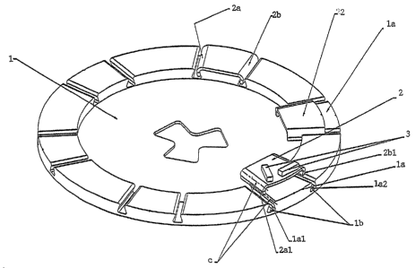
Fig. 1 shows a preferred embodiment of the device according to the invention.
Fig. 2 shows an alternative embodiment of the invention.

Description of embodiments

On the drawing 1 indicates an abrading plate which is mounted rotatably and
for
abrasion is driven by a motor as is explained in more detail in the patent
publication


CA 02529006 2005-12-09
WO 2004/108352 PCT/SE2004/000905
3
cited initially. On the abrading plate is detachably fixed a number of carrier
plates 2
positioned according to a predetermined pattern, each supporting a number of
abrading segments 3 placed in a predetermined manner on the carrier plate 2.

The carrier plates 2 each have two sides 2a, 2b which form an acute angle with
each
other and on the abrading plate 1 are a number of elements 1 a positioned
according
to the said pattern and complementary to the sides 2a, 2b of the respective
carrier
plate. The sides 2a, 2b and the element edges stand in an undercut
relationship to
each other and are directed so that a radius from the centre of the abrading
plate
divides the acute angle pointing towards the abrading plate centre 1 into two
essential
equal parts.

The sides 2a, 2b of the carrier plate 2 are formed with downward and inward
pointing flanges 2a1, 2b1, where the transition between the plane of the
abrading
plate and the plane of flanges 2a1, 2b1 is rounded so that for reasons of
production
and strength the flanges are curved about an imaginary axis c parallel to the
sides 2a,
2b of the carrier plate 2. In the preferred embodiment shown in fig. 1, the
said
complementary-shaped element 1 comprises a shoulder 1 a formed by a radial
groove
lb produced in the abrading plate 1, the side edges 1 al, 1 a2 of which are
intended to
stand in engagement with the sides 1al, 1a2 surrounding the flanges 2a1, 2b 1.
The
tip of the acute angle points radially inwards so that the forces occurring on
abrasion
prevent the carrier plate 2 from leaving the protrusion I a. This achieves the
advantage that the carrier plate 2 is held on the protrusion 1 a with an
engagement
based on friction.

In the embodiment in fig. 2 the element la comprises protrusions projecting
from the
abrading plate 1, otherwise the statements above relating to the embodiment in
fig. 1
apply accordingly.


Representative Drawing
A single figure which represents the drawing illustrating the invention.
Administrative Status

For a clearer understanding of the status of the application/patent presented on this page, the site Disclaimer , as well as the definitions for Patent , Administrative Status , Maintenance Fee  and Payment History  should be consulted.

Administrative Status

Title Date
Forecasted Issue Date 2011-07-26
(86) PCT Filing Date 2004-06-10
(87) PCT Publication Date 2004-12-16
(85) National Entry 2005-12-09
Examination Requested 2009-03-10
(45) Issued 2011-07-26

Abandonment History

There is no abandonment history.

Payment History

Fee Type Anniversary Year Due Date Amount Paid Paid Date
Application Fee $400.00 2005-12-09
Registration of a document - section 124 $100.00 2006-02-28
Maintenance Fee - Application - New Act 2 2006-06-12 $100.00 2006-05-19
Maintenance Fee - Application - New Act 3 2007-06-11 $100.00 2007-05-22
Maintenance Fee - Application - New Act 4 2008-06-10 $100.00 2008-05-22
Request for Examination $800.00 2009-03-10
Maintenance Fee - Application - New Act 5 2009-06-10 $200.00 2009-05-22
Maintenance Fee - Application - New Act 6 2010-06-10 $200.00 2010-05-20
Final Fee $300.00 2011-04-28
Maintenance Fee - Application - New Act 7 2011-06-10 $200.00 2011-05-20
Maintenance Fee - Patent - New Act 8 2012-06-11 $200.00 2012-05-10
Maintenance Fee - Patent - New Act 9 2013-06-10 $200.00 2013-05-08
Maintenance Fee - Patent - New Act 10 2014-06-10 $250.00 2014-05-15
Maintenance Fee - Patent - New Act 11 2015-06-10 $250.00 2015-05-20
Maintenance Fee - Patent - New Act 12 2016-06-10 $250.00 2016-05-18
Maintenance Fee - Patent - New Act 13 2017-06-12 $250.00 2017-05-17
Maintenance Fee - Patent - New Act 14 2018-06-11 $250.00 2018-05-17
Registration of a document - section 124 $100.00 2019-02-14
Maintenance Fee - Patent - New Act 15 2019-06-10 $450.00 2019-05-07
Maintenance Fee - Patent - New Act 16 2020-06-10 $450.00 2020-04-29
Maintenance Fee - Patent - New Act 17 2021-06-10 $459.00 2021-05-12
Maintenance Fee - Patent - New Act 18 2022-06-10 $458.08 2022-05-12
Maintenance Fee - Patent - New Act 19 2023-06-12 $473.65 2023-05-16
Owners on Record

Note: Records showing the ownership history in alphabetical order.

Current Owners on Record
HUSQVARNA AB
Past Owners on Record
HTC SWEDEN AB
OLSEN, LARS
THYSELL, HAKAN
THYSELL, KARL
Past Owners that do not appear in the "Owners on Record" listing will appear in other documentation within the application.
Documents

To view selected files, please enter reCAPTCHA code :


To view images, click a link in the Document Description column. To download the documents, select one or more checkboxes in the first column and then click the "Download Selected in PDF format (Zip Archive)" or the "Download Selected as Single PDF" button.

List of published and non-published patent-specific documents on the CPD .

If you have any difficulty accessing content, you can call the Client Service Centre at 1-866-997-1936 or send them an e-mail at CIPO Client Service Centre.


Document
Description 
Date
(yyyy-mm-dd) 
Number of pages   Size of Image (KB) 
Representative Drawing 2006-02-14 1 17
Cover Page 2006-02-15 1 48
Description 2010-07-07 3 137
Claims 2010-07-07 2 72
Abstract 2005-12-09 2 73
Claims 2005-12-09 2 73
Drawings 2005-12-09 2 39
Description 2005-12-09 3 140
Cover Page 2011-06-23 1 49
Correspondence 2006-02-10 1 27
PCT 2005-12-09 3 104
Assignment 2005-12-09 4 105
Assignment 2006-02-28 2 74
Fees 2006-05-19 1 42
Fees 2007-05-22 1 45
Fees 2008-05-22 1 45
Prosecution-Amendment 2010-03-26 2 76
Prosecution-Amendment 2009-03-10 1 32
Prosecution-Amendment 2009-06-25 2 49
Fees 2009-05-22 1 45
Prosecution-Amendment 2010-07-07 8 290
Correspondence 2011-04-28 1 34