Sélection de la langue

Search

Sommaire du brevet 2529006 

Énoncé de désistement de responsabilité concernant l'information provenant de tiers

Une partie des informations de ce site Web a été fournie par des sources externes. Le gouvernement du Canada n'assume aucune responsabilité concernant la précision, l'actualité ou la fiabilité des informations fournies par les sources externes. Les utilisateurs qui désirent employer cette information devraient consulter directement la source des informations. Le contenu fourni par les sources externes n'est pas assujetti aux exigences sur les langues officielles, la protection des renseignements personnels et l'accessibilité.

Disponibilité de l'Abrégé et des Revendications

L'apparition de différences dans le texte et l'image des Revendications et de l'Abrégé dépend du moment auquel le document est publié. Les textes des Revendications et de l'Abrégé sont affichés :

  • lorsque la demande peut être examinée par le public;
  • lorsque le brevet est émis (délivrance).
(12) Brevet: (11) CA 2529006
(54) Titre français: PLATEAU PORTEUR SUPPORTANT UN ELEMENT ABRASIF ET PLAQUE ABRASIVE
(54) Titre anglais: CARRIER PLATE HOLDING AN ABRADING ELEMENT AND ABRADING PLATE
Statut: Octroyé
Données bibliographiques
(51) Classification internationale des brevets (CIB):
  • B24D 7/06 (2006.01)
  • B24B 7/18 (2006.01)
(72) Inventeurs :
  • THYSELL, HAKAN (Suède)
  • THYSELL, KARL (Suède)
  • OLSEN, LARS (Suède)
(73) Titulaires :
  • HUSQVARNA AB (Suède)
(71) Demandeurs :
  • HTC SWEDEN AB (Suède)
(74) Agent: RIDOUT & MAYBEE LLP
(74) Co-agent:
(45) Délivré: 2011-07-26
(86) Date de dépôt PCT: 2004-06-10
(87) Mise à la disponibilité du public: 2004-12-16
Requête d'examen: 2009-03-10
Licence disponible: S.O.
(25) Langue des documents déposés: Anglais

Traité de coopération en matière de brevets (PCT): Oui
(86) Numéro de la demande PCT: PCT/SE2004/000905
(87) Numéro de publication internationale PCT: WO2004/108352
(85) Entrée nationale: 2005-12-09

(30) Données de priorité de la demande:
Numéro de la demande Pays / territoire Date
0301709-2 Suède 2003-06-11

Abrégés

Abrégé français

L'invention concerne un plateau porteur (2) supportant un élément abrasif, destiné au montage amovible d'une plaque abrasive montée de façon rotative (1) entraînée en fonctionnement, en vue d'abraser des sols en pierre ou en béton, le plateau porteur (2) comportant des côtés (2a, 2b) formant ensemble un angle aigu. Ces côtés (2a, 2b) possèdent des ailes (2a1, 2b1) qui sont formées de manière à se coupler autour d'un épaulement (1a) placé sur la plaque abrasive (1) de manière que le plateau porteur (2) puisse être fixé sur la plaque abrasive (1) par couplage basé sur la forme et la frottement.


Abrégé anglais


The invention concerns a carrier plate (2) holding an abrading element, for
detachable mounting on a rotatably mounted abrading plate (1) driven during
use, for abrading stone or concrete floors, which carrier plate (2) has sides
(2a, 2b) which form an acute angle with each other. The sides (2a, 2b) have
flanges (2a1, 2b1) which are formed for surrounding engagement with a shoulder
(1a) arranged on the abrading plate (1) so that the carrier plate (2) can be
fixed on the abrading plate (1) with an engagement based on form and friction.

Revendications

Note : Les revendications sont présentées dans la langue officielle dans laquelle elles ont été soumises.


4

CLAIMS


1. A carrier plate detachably mounted on a rotatably mounted abrading plate
that
is driven during use to abrade stone or concrete floors, the carrier plate
comprising:

a top surface having a first edge shorter than an opposing second edge;
an abrading element affixed to the top surface;
a first side arranged on a third edge of the top surface;
a second side arranged on a fourth edge of the top surface, the fourth
edge opposing the third edge, the first and second sides forming an acute
angle; and
two flanges, each flange arranged on a respective one of the first and
second sides, the two flanges being provided to engage a shoulder arranged on
the abrading plate by surrounding said shoulder to affix the carrier plate on
the
abrading plate with an engagement based on form and friction, said flanges
being angled inwards towards a centerline of the carrier plate and downwards
towards the abrading plate.

2. An apparatus for abrading stone or concrete floors comprising:
an abrading plate provided to be rotatably driven during use;
a carrier plate detachably mounted on the abrading plate and including
an abrading element;
a first side provided to form an acute angle with respect to a second
side, the acute angle pointing towards a center of the abrading plate, a
radius
from the center of the abrading plate dividing the each of the acute angle and

the carrier plate into equal parts; and

two flanges, each flange arranged on a respective one of the first and
second sides, the two flanges being provided to engage a shoulder arranged on
the abrading plate by surrounding said shoulder to axially affix the carrier
plate on the abrading plate within a circumference of the abrading plate, the
carrier plate being affixed with an engagement based on form and friction, the

two flanges being angled inward toward a centerline of the carrier plate.


3. A carrier plate detachably mounted on a rotatably mounted abrading plate
driven during use to abrade stone or concrete floors, the carrier plate
comprising:
a top surface having a first edge shorter than an opposing second edge;
an abrading element affixed to the top surface;
a first side arranged on a third edge of the top surface;
a second side arranged on a fourth edge of the top surface, the fourth
edge opposing the third edge, the first and second sides forming an acute
angle; and
two flanges, each flange arranged on a respective one of the first and
second sides, the two flanges being provided to engage a shoulder arranged on
the abrading plate by surrounding said shoulder to affix the carrier plate can
on
the abrading plate with an engagement based on form and friction, the flanges
being rounded about an axis parallel to the respective sides to contact
complementary-shaped surfaces on the shoulder of the abrading plate.

4. The abrading apparatus according to claim 2, wherein the two flanges are
rounded about an axis parallel to the respective sides to contact
complementary-shaped surfaces on the shoulder of the abrading plate.

Description

Note : Les descriptions sont présentées dans la langue officielle dans laquelle elles ont été soumises.


CA 02529006 2010-07-07

WO 2004/108352 PCT/SE2004/000905
1
CARRIER PLATE HOLDING AN ABRADING ELEMENT
AND ABRADING PLATE
Technical field
The present invention concerns a carrier plate holding an abrading element and
an
abrading plate device according to the preamble of the respective independent
claims.

Technical background
A machine, preferably for abrading stone and concrete floors, is known for
example
from PCT/SE93/00865. The abrading element, fixed on a carrier plate which in
turn
is detachably mounted on the abrading plate, must be considered a consumable.
Changing the abrading element is labour-intensive and time-consuming, and
adversely affects the production time of the abrading machine.

Examples of known devices for detachable mounting of abrading elements on
abrading discs are shown in DE-1 127 745, US-1,470,957 and US-5,076,023.
Summary of the invention
The object of the present invention is to produce a device of the type
described
initially which facilitates the replacement of the abrading element and hence
contributes to a better working environment and increased production.

Thus a carrier plate holding an abrading element is produced, for detachable
mounting on a rotatably mounted abrading plate driven during use, for abrading
stone or concrete floors, which carrier plate has sides which form an acute
angle with
each other. The carrier plate is characterised in that the sides have flanges
which are
designed for surrounding engagement with a shoulder arranged on the abrading
plate
so that the carrier plate can be fixed on the abrading plate with an
engagement based
on form and friction.


CA 02529006 2005-12-09
WO 2004/108352 PCT/SE2004/000905
2
An abrading plate is also produced for abrading stone or concrete floors,
which
abrading plate is rotatably mounted and driven during use and formed for
detachable
mounting of at least one carrier plate holding an abrading element. The
abrading
plate is characterised by a shoulder arranged on the abrading plate which has
side
edges forming an acute angle with each other and which is designed for
engagement
with flanges arranged on the carrier plate so that the carrier plate by
surrounding
engagement can be fixed on the abrading plate in an engagement based on form
and
friction.

The invention thus achieves the simplified mounting of carrier plates on the
abrading
plate, which mounting is also quick to both establish and release.

As a particular characteristic of the invention shows, because of the acute
angle
between the undercut groove and naturally also between the corresponding edges
shaped complementary to the groove on the carrier plate, the engagement
between
the groove and the carrier plate edges can be established and released very
quickly.
Carrier plates according to the invention also have the advantage that they
can be
produced at relatively low cost.
Brief description of the drawings

The invention will be explained below in more detail with reference to the
enclosed
drawings.

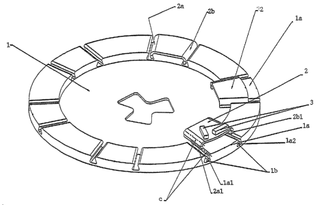
Fig. 1 shows a preferred embodiment of the device according to the invention.
Fig. 2 shows an alternative embodiment of the invention.

Description of embodiments

On the drawing 1 indicates an abrading plate which is mounted rotatably and
for
abrasion is driven by a motor as is explained in more detail in the patent
publication


CA 02529006 2005-12-09
WO 2004/108352 PCT/SE2004/000905
3
cited initially. On the abrading plate is detachably fixed a number of carrier
plates 2
positioned according to a predetermined pattern, each supporting a number of
abrading segments 3 placed in a predetermined manner on the carrier plate 2.

The carrier plates 2 each have two sides 2a, 2b which form an acute angle with
each
other and on the abrading plate 1 are a number of elements 1 a positioned
according
to the said pattern and complementary to the sides 2a, 2b of the respective
carrier
plate. The sides 2a, 2b and the element edges stand in an undercut
relationship to
each other and are directed so that a radius from the centre of the abrading
plate
divides the acute angle pointing towards the abrading plate centre 1 into two
essential
equal parts.

The sides 2a, 2b of the carrier plate 2 are formed with downward and inward
pointing flanges 2a1, 2b1, where the transition between the plane of the
abrading
plate and the plane of flanges 2a1, 2b1 is rounded so that for reasons of
production
and strength the flanges are curved about an imaginary axis c parallel to the
sides 2a,
2b of the carrier plate 2. In the preferred embodiment shown in fig. 1, the
said
complementary-shaped element 1 comprises a shoulder 1 a formed by a radial
groove
lb produced in the abrading plate 1, the side edges 1 al, 1 a2 of which are
intended to
stand in engagement with the sides 1al, 1a2 surrounding the flanges 2a1, 2b 1.
The
tip of the acute angle points radially inwards so that the forces occurring on
abrasion
prevent the carrier plate 2 from leaving the protrusion I a. This achieves the
advantage that the carrier plate 2 is held on the protrusion 1 a with an
engagement
based on friction.

In the embodiment in fig. 2 the element la comprises protrusions projecting
from the
abrading plate 1, otherwise the statements above relating to the embodiment in
fig. 1
apply accordingly.


Dessin représentatif
Une figure unique qui représente un dessin illustrant l'invention.
États administratifs

Pour une meilleure compréhension de l'état de la demande ou brevet qui figure sur cette page, la rubrique Mise en garde , et les descriptions de Brevet , États administratifs , Taxes périodiques et Historique des paiements devraient être consultées.

États administratifs

Titre Date
Date de délivrance prévu 2011-07-26
(86) Date de dépôt PCT 2004-06-10
(87) Date de publication PCT 2004-12-16
(85) Entrée nationale 2005-12-09
Requête d'examen 2009-03-10
(45) Délivré 2011-07-26

Historique d'abandonnement

Il n'y a pas d'historique d'abandonnement

Historique des paiements

Type de taxes Anniversaire Échéance Montant payé Date payée
Le dépôt d'une demande de brevet 400,00 $ 2005-12-09
Enregistrement de documents 100,00 $ 2006-02-28
Taxe de maintien en état - Demande - nouvelle loi 2 2006-06-12 100,00 $ 2006-05-19
Taxe de maintien en état - Demande - nouvelle loi 3 2007-06-11 100,00 $ 2007-05-22
Taxe de maintien en état - Demande - nouvelle loi 4 2008-06-10 100,00 $ 2008-05-22
Requête d'examen 800,00 $ 2009-03-10
Taxe de maintien en état - Demande - nouvelle loi 5 2009-06-10 200,00 $ 2009-05-22
Taxe de maintien en état - Demande - nouvelle loi 6 2010-06-10 200,00 $ 2010-05-20
Taxe finale 300,00 $ 2011-04-28
Taxe de maintien en état - Demande - nouvelle loi 7 2011-06-10 200,00 $ 2011-05-20
Taxe de maintien en état - brevet - nouvelle loi 8 2012-06-11 200,00 $ 2012-05-10
Taxe de maintien en état - brevet - nouvelle loi 9 2013-06-10 200,00 $ 2013-05-08
Taxe de maintien en état - brevet - nouvelle loi 10 2014-06-10 250,00 $ 2014-05-15
Taxe de maintien en état - brevet - nouvelle loi 11 2015-06-10 250,00 $ 2015-05-20
Taxe de maintien en état - brevet - nouvelle loi 12 2016-06-10 250,00 $ 2016-05-18
Taxe de maintien en état - brevet - nouvelle loi 13 2017-06-12 250,00 $ 2017-05-17
Taxe de maintien en état - brevet - nouvelle loi 14 2018-06-11 250,00 $ 2018-05-17
Enregistrement de documents 100,00 $ 2019-02-14
Taxe de maintien en état - brevet - nouvelle loi 15 2019-06-10 450,00 $ 2019-05-07
Taxe de maintien en état - brevet - nouvelle loi 16 2020-06-10 450,00 $ 2020-04-29
Taxe de maintien en état - brevet - nouvelle loi 17 2021-06-10 459,00 $ 2021-05-12
Taxe de maintien en état - brevet - nouvelle loi 18 2022-06-10 458,08 $ 2022-05-12
Taxe de maintien en état - brevet - nouvelle loi 19 2023-06-12 473,65 $ 2023-05-16
Titulaires au dossier

Les titulaires actuels et antérieures au dossier sont affichés en ordre alphabétique.

Titulaires actuels au dossier
HUSQVARNA AB
Titulaires antérieures au dossier
HTC SWEDEN AB
OLSEN, LARS
THYSELL, HAKAN
THYSELL, KARL
Les propriétaires antérieurs qui ne figurent pas dans la liste des « Propriétaires au dossier » apparaîtront dans d'autres documents au dossier.
Documents

Pour visionner les fichiers sélectionnés, entrer le code reCAPTCHA :


Pour visualiser une image, cliquer sur un lien dans la colonne description du document. Pour télécharger l'image (les images), cliquer l'une ou plusieurs cases à cocher dans la première colonne et ensuite cliquer sur le bouton "Télécharger sélection en format PDF (archive Zip)" ou le bouton "Télécharger sélection (en un fichier PDF fusionné)".

Liste des documents de brevet publiés et non publiés sur la BDBC .

Si vous avez des difficultés à accéder au contenu, veuillez communiquer avec le Centre de services à la clientèle au 1-866-997-1936, ou envoyer un courriel au Centre de service à la clientèle de l'OPIC.


Description du
Document 
Date
(yyyy-mm-dd) 
Nombre de pages   Taille de l'image (Ko) 
Dessins représentatifs 2006-02-14 1 17
Page couverture 2006-02-15 1 48
Description 2010-07-07 3 137
Revendications 2010-07-07 2 72
Abrégé 2005-12-09 2 73
Revendications 2005-12-09 2 73
Dessins 2005-12-09 2 39
Description 2005-12-09 3 140
Page couverture 2011-06-23 1 49
Correspondance 2006-02-10 1 27
PCT 2005-12-09 3 104
Cession 2005-12-09 4 105
Cession 2006-02-28 2 74
Taxes 2006-05-19 1 42
Taxes 2007-05-22 1 45
Taxes 2008-05-22 1 45
Poursuite-Amendment 2010-03-26 2 76
Poursuite-Amendment 2009-03-10 1 32
Poursuite-Amendment 2009-06-25 2 49
Taxes 2009-05-22 1 45
Poursuite-Amendment 2010-07-07 8 290
Correspondance 2011-04-28 1 34