Language selection

Search

Patent 2571637 Summary

Third-party information liability

Some of the information on this Web page has been provided by external sources. The Government of Canada is not responsible for the accuracy, reliability or currency of the information supplied by external sources. Users wishing to rely upon this information should consult directly with the source of the information. Content provided by external sources is not subject to official languages, privacy and accessibility requirements.

Claims and Abstract availability

Any discrepancies in the text and image of the Claims and Abstract are due to differing posting times. Text of the Claims and Abstract are posted:

  • At the time the application is open to public inspection;
  • At the time of issue of the patent (grant).
(12) Patent: (11) CA 2571637
(54) English Title: HOLDING FRAME FOR CONNECTOR MODULES
(54) French Title: BATI DE FIXATION POUR MODULES A CONNECTEURS
Status: Deemed expired
Bibliographic Data
(51) International Patent Classification (IPC):
  • H01R 13/514 (2006.01)
(72) Inventors :
  • FERDERER, ALBERT (Germany)
(73) Owners :
  • HARTING ELECTRIC GMBH & CO. KG (Germany)
(71) Applicants :
  • HARTING ELECTRIC GMBH & CO. KG (Germany)
(74) Agent: BORDEN LADNER GERVAIS LLP
(74) Associate agent:
(45) Issued: 2009-09-22
(22) Filed Date: 2006-12-15
(41) Open to Public Inspection: 2007-06-22
Examination requested: 2006-12-15
Availability of licence: N/A
(25) Language of filing: English

Patent Cooperation Treaty (PCT): No

(30) Application Priority Data:
Application No. Country/Territory Date
20 2005 02 0026.3 Germany 2005-12-22

Abstracts

English Abstract

The invention proposes a one-piece holding frame of plastic for a plug-type connector, in which several connector modules are arranged adjacent to one another, wherein several wall segments with window-like openings are formed in the collar-shaped mating side of said holding frame by means of slots. Two wall segments that lie opposite of one another respectively form a receptacle for one connector module, wherein projections arranged on the connector modules snap into the openings of the holding frame when the connector modules are inserted into the holding frame.


French Abstract

L'invention propose un bâti de fixation monobloc en plastique pour un connecteur de type fiche, dans lequel plusieurs modules de connecteur sont adjacents l'un à l'autre. Plusieurs segments de parois avec des ouvertures semblables à des fenêtres sont formés, dans le côté d'appariement en forme de collet du bâti de fixation, au moyen de fentes. Deux segments de parois opposés l'un à l'autre forment respectivement un connecteur femelle pour un module de connecteur. Des projections disposées sur les modules de connecteur s'encliquettent dans les ouvertures du bâti de fixation lorsque les modules de connecteur sont insérés dans ce bâti.

Claims

Note: Claims are shown in the official language in which they were submitted.


CLAIMS:


1. A holding frame for a plug-connector made of a plastic material for
accommodating multiple connector modules adjacent to one another on a
mating side of the holding frame, the holding frame comprising a wall
having multiple wall segments respectively separated by slots on the
mating side for permitting elastic outward bending of the wall segments,
the wall segments being arranged in pairs of symmetrically opposing wall
segments, each pair forming a receptacle for one connector module,
each wall segment having a window-like opening, and a connector guide
groove, wherein the connector guide groove is positioned above the
window-like opening and is formed by a window partition integrally
moulded onto an outer side of the wall segment and having a connector
insertion guide ramp on an inner side.


2. The holding frame according to Claim 1 for receiving at least one
connector module having projections arranged on narrow sides of the
connector module, wherein each connector guide groove has an insertion
ramp for engagement by the projections on the connector module and
the window-like openings are shaped and sized to receive the
projections, whereby the wall segments are bent outward upon
engagement of the projections with and movement along the insertion
ramp and the guide groove and spring back once the projections are
engaged in the window-like openings.


Description

Note: Descriptions are shown in the official language in which they were submitted.


CA 02571637 2006-12-15
HOLDING FRAME FOR CONNECTOR MODULES
BACKGROUND OF THE INVENTION

1. Field of the Invention

The invention pertains to a one-piece holding frame that consists of a plastic
material and serves for accommodating several connector modules arranged
is adjacent to one another.

2. Description of the related art

A holding frame of this type is required for combining several connector
modules with partially different mating configurations in a connector housing
and to connect said connector modules to a corresponding mating connec-
tor.

DE 197 076 120 C1 discloses a mounting frame for holding connector mod-
ules, wherein this mounting frame is composed of two halves that are con-
nected to one another in an articulated fashion, and wherein the connector
modules that can be inserted into recesses in the mounting frame are held
with a positive fit when the two halves are closed.


CA 02571637 2006-12-15

2
SUMMARY OF THE INVENTION

Consequently, the invention is based on the objective of realizing a one-
piece holding frame of plastic of the initially cited type in such a way that
al-
ready known connector modules can be reliably interlocked and held therein.
This objective is attained in that the holding frame features several wall seg-

ments on its mating side that are separated from one another by slots,
wherein two wall segments that are arranged symmetrically opposite of one
another respectively form a receptacle for one connector module.
The advantages attained with the invention can be seen, in particular, in that
a holding frame in the form of a one-piece moulded plastic part can be
manufactured much easier, for example, than an articulated metallic holding
frame. In addition, connector modules with electric contacts arranged therein
can be inserted and interlocked in the holding frame more easily because the
is plastic materials slide very well on one another. To this end, the
longitudinal
walls of the collar-shaped holding frame on the mating side are divided into
several wall segments by means of slots, wherein two wall segments that are
arranged symmetrically opposite of one another respectively form a plug-in
area or receptacle for one connector module.
It is also advantageous that the wall segments feature a window-like open-
ing, above which a guide groove is arranged such that the connector mod-
ules provided with integral projections on the narrow sides can be inserted
into a guide groove provided with an insertion ramp and the springable wall
segments are briefly pressed outward before the projections snap into the
openings.
In addition, the connector modules feature interlocking arms that are inte-
grally moulded onto their narrow sides such that they act in the direction of
the cable connection side and engage underneath the lateral collar wall
when the projections snap into the openings such that two independent inter-
locking means fix the connector modules in the holding frame.


CA 02571637 2006-12-15

3
BRIEF DESCRIPTION OF THE DRAWINGS

One embodiment of the invention is illustrated in the figures and described in
greater detail below. The figures show:
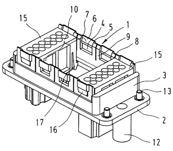
Fig. 1 is a holding frame with connector modules viewed from the mating
side, and

Fig. 2 is the holding frame with connector modules viewed from the cable
connections.

DESCRIPTION OF THE PREFERRED EMBODYMENTS

Figure 1 shows a holding frame that is entirely made of plastic and designed
for accommodating individual connector modules 15 to be inserted therein.
The holding frame features a rectangular flange-like frame 2 with a periph-
eral collar 3 integrally moulded thereon such that it extends perpendicular to
the frame.

Window-like openings 4 are provided on the longitudinal sides, wherein the
end of said openings on the mating side is formed by a window partition 5
that is outwardly offset by approximately the wall thickness.
Slots 8 are provided to both sides of the openings 4 and extend approxi-
mately to the center of the collar height such that they respectively form an
elastic wall segment 9.

Two oppositely arranged wall segments 9 respectively form a receptacle 10
for one connector module.

When a connector module 15 is inserted into a receptacle 10 in the holding
frame 1, the projections 16 arranged on the narrow sides of the connector


CA 02571637 2006-12-15

4
module are initially inserted into the insertion ramps 6 of the guide grooves
7
such that the respectively opposite wall segments 9 are bent outward until
the projections 16 snap into the window-like openings 4 and the wall seg-
ments spring back.
Interlocking arms 17 are also integrally moulded onto the narrow sides of the
connector modules 15 and pressed together along the wall segments 9 when
a connector module is inserted into the holding frame from the mating side,
wherein said interlocking arms encounter an enlarged opening underneath
the collar 3 that is formed by the flanged frame 2 situated underneath the
collar such that the interlocking arms 17 are interlocked with the lower edge
of the collar once they unbend outward. The modules therefore are secured
in the holding frame by means of two independent interlocking means.

Figure 2 shows the holding frame with two interlocked connector modules in
the form of a view from the connection side.
Two encoding elements 12 realized in the form of a pin and a socket are ar-
ranged on the surfaces of the narrow sides of the frame-shaped flange 2 in
order to ensure the non-interchangeable mating with a correspondingly de-
signed mating connector.

On the outer edges of the flange, four screw elements 13 can be inserted
into openings on the narrow sides, wherein said screw elements feature pins
that penetrate the flange and serve for fixing the holding frame in a not-
shown connector housing.

This figure also shows the interlocking of the connector modules, wherein
the hook-shaped interlocking arms 17 are interlocked in the enlarged inner
recess with the edge of the collar situated thereunder.


Representative Drawing
A single figure which represents the drawing illustrating the invention.
Administrative Status

For a clearer understanding of the status of the application/patent presented on this page, the site Disclaimer , as well as the definitions for Patent , Administrative Status , Maintenance Fee  and Payment History  should be consulted.

Administrative Status

Title Date
Forecasted Issue Date 2009-09-22
(22) Filed 2006-12-15
Examination Requested 2006-12-15
(41) Open to Public Inspection 2007-06-22
(45) Issued 2009-09-22
Deemed Expired 2013-12-17

Abandonment History

There is no abandonment history.

Payment History

Fee Type Anniversary Year Due Date Amount Paid Paid Date
Request for Examination $800.00 2006-12-15
Registration of a document - section 124 $100.00 2006-12-15
Application Fee $400.00 2006-12-15
Maintenance Fee - Application - New Act 2 2008-12-15 $100.00 2008-11-10
Final Fee $300.00 2009-07-08
Maintenance Fee - Patent - New Act 3 2009-12-15 $100.00 2009-11-13
Maintenance Fee - Patent - New Act 4 2010-12-15 $100.00 2010-09-16
Maintenance Fee - Patent - New Act 5 2011-12-15 $200.00 2011-09-14
Owners on Record

Note: Records showing the ownership history in alphabetical order.

Current Owners on Record
HARTING ELECTRIC GMBH & CO. KG
Past Owners on Record
FERDERER, ALBERT
Past Owners that do not appear in the "Owners on Record" listing will appear in other documentation within the application.
Documents

To view selected files, please enter reCAPTCHA code :


To view images, click a link in the Document Description column. To download the documents, select one or more checkboxes in the first column and then click the "Download Selected in PDF format (Zip Archive)" or the "Download Selected as Single PDF" button.

List of published and non-published patent-specific documents on the CPD .

If you have any difficulty accessing content, you can call the Client Service Centre at 1-866-997-1936 or send them an e-mail at CIPO Client Service Centre.


Document
Description 
Date
(yyyy-mm-dd) 
Number of pages   Size of Image (KB) 
Abstract 2006-12-15 1 16
Description 2006-12-15 4 149
Claims 2006-12-15 1 21
Drawings 2006-12-15 2 39
Representative Drawing 2007-05-25 1 15
Cover Page 2007-06-19 1 42
Claims 2008-10-03 1 37
Cover Page 2009-08-31 2 47
Assignment 2006-12-15 4 128
Prosecution-Amendment 2008-05-02 2 59
Prosecution-Amendment 2008-10-03 3 145
Correspondence 2009-07-08 1 33