Sélection de la langue

Search

Sommaire du brevet 2571637 

Énoncé de désistement de responsabilité concernant l'information provenant de tiers

Une partie des informations de ce site Web a été fournie par des sources externes. Le gouvernement du Canada n'assume aucune responsabilité concernant la précision, l'actualité ou la fiabilité des informations fournies par les sources externes. Les utilisateurs qui désirent employer cette information devraient consulter directement la source des informations. Le contenu fourni par les sources externes n'est pas assujetti aux exigences sur les langues officielles, la protection des renseignements personnels et l'accessibilité.

Disponibilité de l'Abrégé et des Revendications

L'apparition de différences dans le texte et l'image des Revendications et de l'Abrégé dépend du moment auquel le document est publié. Les textes des Revendications et de l'Abrégé sont affichés :

  • lorsque la demande peut être examinée par le public;
  • lorsque le brevet est émis (délivrance).
(12) Brevet: (11) CA 2571637
(54) Titre français: BATI DE FIXATION POUR MODULES A CONNECTEURS
(54) Titre anglais: HOLDING FRAME FOR CONNECTOR MODULES
Statut: Réputé périmé
Données bibliographiques
(51) Classification internationale des brevets (CIB):
  • H01R 13/514 (2006.01)
(72) Inventeurs :
  • FERDERER, ALBERT (Allemagne)
(73) Titulaires :
  • HARTING ELECTRIC GMBH & CO. KG (Allemagne)
(71) Demandeurs :
  • HARTING ELECTRIC GMBH & CO. KG (Allemagne)
(74) Agent: BORDEN LADNER GERVAIS LLP
(74) Co-agent:
(45) Délivré: 2009-09-22
(22) Date de dépôt: 2006-12-15
(41) Mise à la disponibilité du public: 2007-06-22
Requête d'examen: 2006-12-15
Licence disponible: S.O.
(25) Langue des documents déposés: Anglais

Traité de coopération en matière de brevets (PCT): Non

(30) Données de priorité de la demande:
Numéro de la demande Pays / territoire Date
20 2005 02 0026.3 Allemagne 2005-12-22

Abrégés

Abrégé français

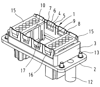
L'invention propose un bâti de fixation monobloc en plastique pour un connecteur de type fiche, dans lequel plusieurs modules de connecteur sont adjacents l'un à l'autre. Plusieurs segments de parois avec des ouvertures semblables à des fenêtres sont formés, dans le côté d'appariement en forme de collet du bâti de fixation, au moyen de fentes. Deux segments de parois opposés l'un à l'autre forment respectivement un connecteur femelle pour un module de connecteur. Des projections disposées sur les modules de connecteur s'encliquettent dans les ouvertures du bâti de fixation lorsque les modules de connecteur sont insérés dans ce bâti.


Abrégé anglais

The invention proposes a one-piece holding frame of plastic for a plug-type connector, in which several connector modules are arranged adjacent to one another, wherein several wall segments with window-like openings are formed in the collar-shaped mating side of said holding frame by means of slots. Two wall segments that lie opposite of one another respectively form a receptacle for one connector module, wherein projections arranged on the connector modules snap into the openings of the holding frame when the connector modules are inserted into the holding frame.

Revendications

Note : Les revendications sont présentées dans la langue officielle dans laquelle elles ont été soumises.


CLAIMS:


1. A holding frame for a plug-connector made of a plastic material for
accommodating multiple connector modules adjacent to one another on a
mating side of the holding frame, the holding frame comprising a wall
having multiple wall segments respectively separated by slots on the
mating side for permitting elastic outward bending of the wall segments,
the wall segments being arranged in pairs of symmetrically opposing wall
segments, each pair forming a receptacle for one connector module,
each wall segment having a window-like opening, and a connector guide
groove, wherein the connector guide groove is positioned above the
window-like opening and is formed by a window partition integrally
moulded onto an outer side of the wall segment and having a connector
insertion guide ramp on an inner side.


2. The holding frame according to Claim 1 for receiving at least one
connector module having projections arranged on narrow sides of the
connector module, wherein each connector guide groove has an insertion
ramp for engagement by the projections on the connector module and
the window-like openings are shaped and sized to receive the
projections, whereby the wall segments are bent outward upon
engagement of the projections with and movement along the insertion
ramp and the guide groove and spring back once the projections are
engaged in the window-like openings.


Description

Note : Les descriptions sont présentées dans la langue officielle dans laquelle elles ont été soumises.


CA 02571637 2006-12-15
HOLDING FRAME FOR CONNECTOR MODULES
BACKGROUND OF THE INVENTION

1. Field of the Invention

The invention pertains to a one-piece holding frame that consists of a plastic
material and serves for accommodating several connector modules arranged
is adjacent to one another.

2. Description of the related art

A holding frame of this type is required for combining several connector
modules with partially different mating configurations in a connector housing
and to connect said connector modules to a corresponding mating connec-
tor.

DE 197 076 120 C1 discloses a mounting frame for holding connector mod-
ules, wherein this mounting frame is composed of two halves that are con-
nected to one another in an articulated fashion, and wherein the connector
modules that can be inserted into recesses in the mounting frame are held
with a positive fit when the two halves are closed.


CA 02571637 2006-12-15

2
SUMMARY OF THE INVENTION

Consequently, the invention is based on the objective of realizing a one-
piece holding frame of plastic of the initially cited type in such a way that
al-
ready known connector modules can be reliably interlocked and held therein.
This objective is attained in that the holding frame features several wall seg-

ments on its mating side that are separated from one another by slots,
wherein two wall segments that are arranged symmetrically opposite of one
another respectively form a receptacle for one connector module.
The advantages attained with the invention can be seen, in particular, in that
a holding frame in the form of a one-piece moulded plastic part can be
manufactured much easier, for example, than an articulated metallic holding
frame. In addition, connector modules with electric contacts arranged therein
can be inserted and interlocked in the holding frame more easily because the
is plastic materials slide very well on one another. To this end, the
longitudinal
walls of the collar-shaped holding frame on the mating side are divided into
several wall segments by means of slots, wherein two wall segments that are
arranged symmetrically opposite of one another respectively form a plug-in
area or receptacle for one connector module.
It is also advantageous that the wall segments feature a window-like open-
ing, above which a guide groove is arranged such that the connector mod-
ules provided with integral projections on the narrow sides can be inserted
into a guide groove provided with an insertion ramp and the springable wall
segments are briefly pressed outward before the projections snap into the
openings.
In addition, the connector modules feature interlocking arms that are inte-
grally moulded onto their narrow sides such that they act in the direction of
the cable connection side and engage underneath the lateral collar wall
when the projections snap into the openings such that two independent inter-
locking means fix the connector modules in the holding frame.


CA 02571637 2006-12-15

3
BRIEF DESCRIPTION OF THE DRAWINGS

One embodiment of the invention is illustrated in the figures and described in
greater detail below. The figures show:
Fig. 1 is a holding frame with connector modules viewed from the mating
side, and

Fig. 2 is the holding frame with connector modules viewed from the cable
connections.

DESCRIPTION OF THE PREFERRED EMBODYMENTS

Figure 1 shows a holding frame that is entirely made of plastic and designed
for accommodating individual connector modules 15 to be inserted therein.
The holding frame features a rectangular flange-like frame 2 with a periph-
eral collar 3 integrally moulded thereon such that it extends perpendicular to
the frame.

Window-like openings 4 are provided on the longitudinal sides, wherein the
end of said openings on the mating side is formed by a window partition 5
that is outwardly offset by approximately the wall thickness.
Slots 8 are provided to both sides of the openings 4 and extend approxi-
mately to the center of the collar height such that they respectively form an
elastic wall segment 9.

Two oppositely arranged wall segments 9 respectively form a receptacle 10
for one connector module.

When a connector module 15 is inserted into a receptacle 10 in the holding
frame 1, the projections 16 arranged on the narrow sides of the connector


CA 02571637 2006-12-15

4
module are initially inserted into the insertion ramps 6 of the guide grooves
7
such that the respectively opposite wall segments 9 are bent outward until
the projections 16 snap into the window-like openings 4 and the wall seg-
ments spring back.
Interlocking arms 17 are also integrally moulded onto the narrow sides of the
connector modules 15 and pressed together along the wall segments 9 when
a connector module is inserted into the holding frame from the mating side,
wherein said interlocking arms encounter an enlarged opening underneath
the collar 3 that is formed by the flanged frame 2 situated underneath the
collar such that the interlocking arms 17 are interlocked with the lower edge
of the collar once they unbend outward. The modules therefore are secured
in the holding frame by means of two independent interlocking means.

Figure 2 shows the holding frame with two interlocked connector modules in
the form of a view from the connection side.
Two encoding elements 12 realized in the form of a pin and a socket are ar-
ranged on the surfaces of the narrow sides of the frame-shaped flange 2 in
order to ensure the non-interchangeable mating with a correspondingly de-
signed mating connector.

On the outer edges of the flange, four screw elements 13 can be inserted
into openings on the narrow sides, wherein said screw elements feature pins
that penetrate the flange and serve for fixing the holding frame in a not-
shown connector housing.

This figure also shows the interlocking of the connector modules, wherein
the hook-shaped interlocking arms 17 are interlocked in the enlarged inner
recess with the edge of the collar situated thereunder.


Dessin représentatif
Une figure unique qui représente un dessin illustrant l'invention.
États administratifs

Pour une meilleure compréhension de l'état de la demande ou brevet qui figure sur cette page, la rubrique Mise en garde , et les descriptions de Brevet , États administratifs , Taxes périodiques et Historique des paiements devraient être consultées.

États administratifs

Titre Date
Date de délivrance prévu 2009-09-22
(22) Dépôt 2006-12-15
Requête d'examen 2006-12-15
(41) Mise à la disponibilité du public 2007-06-22
(45) Délivré 2009-09-22
Réputé périmé 2013-12-17

Historique d'abandonnement

Il n'y a pas d'historique d'abandonnement

Historique des paiements

Type de taxes Anniversaire Échéance Montant payé Date payée
Requête d'examen 800,00 $ 2006-12-15
Enregistrement de documents 100,00 $ 2006-12-15
Le dépôt d'une demande de brevet 400,00 $ 2006-12-15
Taxe de maintien en état - Demande - nouvelle loi 2 2008-12-15 100,00 $ 2008-11-10
Taxe finale 300,00 $ 2009-07-08
Taxe de maintien en état - brevet - nouvelle loi 3 2009-12-15 100,00 $ 2009-11-13
Taxe de maintien en état - brevet - nouvelle loi 4 2010-12-15 100,00 $ 2010-09-16
Taxe de maintien en état - brevet - nouvelle loi 5 2011-12-15 200,00 $ 2011-09-14
Titulaires au dossier

Les titulaires actuels et antérieures au dossier sont affichés en ordre alphabétique.

Titulaires actuels au dossier
HARTING ELECTRIC GMBH & CO. KG
Titulaires antérieures au dossier
FERDERER, ALBERT
Les propriétaires antérieurs qui ne figurent pas dans la liste des « Propriétaires au dossier » apparaîtront dans d'autres documents au dossier.
Documents

Pour visionner les fichiers sélectionnés, entrer le code reCAPTCHA :


Pour visualiser une image, cliquer sur un lien dans la colonne description du document. Pour télécharger l'image (les images), cliquer l'une ou plusieurs cases à cocher dans la première colonne et ensuite cliquer sur le bouton "Télécharger sélection en format PDF (archive Zip)" ou le bouton "Télécharger sélection (en un fichier PDF fusionné)".

Liste des documents de brevet publiés et non publiés sur la BDBC .

Si vous avez des difficultés à accéder au contenu, veuillez communiquer avec le Centre de services à la clientèle au 1-866-997-1936, ou envoyer un courriel au Centre de service à la clientèle de l'OPIC.


Description du
Document 
Date
(yyyy-mm-dd) 
Nombre de pages   Taille de l'image (Ko) 
Abrégé 2006-12-15 1 16
Description 2006-12-15 4 149
Revendications 2006-12-15 1 21
Dessins 2006-12-15 2 39
Dessins représentatifs 2007-05-25 1 15
Page couverture 2007-06-19 1 42
Revendications 2008-10-03 1 37
Page couverture 2009-08-31 2 47
Cession 2006-12-15 4 128
Poursuite-Amendment 2008-05-02 2 59
Poursuite-Amendment 2008-10-03 3 145
Correspondance 2009-07-08 1 33