Language selection

Search

Patent 2580089 Summary

Third-party information liability

Some of the information on this Web page has been provided by external sources. The Government of Canada is not responsible for the accuracy, reliability or currency of the information supplied by external sources. Users wishing to rely upon this information should consult directly with the source of the information. Content provided by external sources is not subject to official languages, privacy and accessibility requirements.

Claims and Abstract availability

Any discrepancies in the text and image of the Claims and Abstract are due to differing posting times. Text of the Claims and Abstract are posted:

  • At the time the application is open to public inspection;
  • At the time of issue of the patent (grant).
(12) Patent: (11) CA 2580089
(54) English Title: A METHOD FOR APPLYING A PROTECTIVE STRIP ONTO A CATHODE PLATE FOR OBTAINING A METAL IN AN ELECTROLYTIC MANNER FROM AN ELECTROLYTIC FLUID
(54) French Title: METHODE D'APPLICATION D'UNE BANDE PROTECTRICE A UNE PLAQUE CATHODE POUR OBTENIR PAR ELECTROLYSE UN METAL A PARTIR D'UN FLUIDE ELECTROLYTIQUE
Status: Granted
Bibliographic Data
(51) International Patent Classification (IPC):
  • C25C 7/02 (2006.01)
(72) Inventors :
  • SCHNITZLBAUMER, JOSEF (Austria)
  • ANGER, GERHARD (Austria)
  • LEITNER, MARKUS (Austria)
  • GERNER, GERHARD (Austria)
(73) Owners :
  • AMAG ROLLING GMBH (Austria)
(71) Applicants :
  • AMAG ROLLING GMBH (Austria)
(74) Agent: SMART & BIGGAR LP
(74) Associate agent:
(45) Issued: 2012-01-24
(86) PCT Filing Date: 2005-09-13
(87) Open to Public Inspection: 2006-03-23
Examination requested: 2010-03-25
Availability of licence: N/A
(25) Language of filing: English

Patent Cooperation Treaty (PCT): Yes
(86) PCT Filing Number: PCT/AT2005/000363
(87) International Publication Number: WO2006/029428
(85) National Entry: 2007-03-12

(30) Application Priority Data:
Application No. Country/Territory Date
A 1523/2004 Austria 2004-09-13

Abstracts

English Abstract


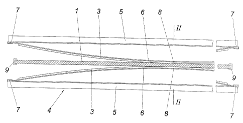
The invention relates to a method for applying a protective strip (3) to a
cathode sheet (1) for electrolytically obtaining a metal from a electrolytic
fluid. The plastic protective strip presses onto the warmed cathode sheet with
the aid of a pressing tool (4), said cathode sheet being arranged below a melt
of the surface thereof facing the cathode sheet and is subsequently cooled
over the cathode sheet. The protective strip is applied to an elastically
flexible pressing tool, which is pre-curved counter to the cathode sheet, in
the direction of pressing in order to ensure a tight fitting thereof, and is
pressed, in an outwardly progressive manner, onto the cathode sheet by the
curving of the pressing tool in a defined positioning area.


French Abstract

L'invention concerne un procédé pour appliquer une bande de protection sur une plaque cathodique pour l'extraction électrolytique d'un métal contenu dans un liquide électrolytique, cette bande de protection en matière plastique étant compressée contre la plaque cathodique chauffée, au moyen d'un outil de compression, jusqu'à la fonte de sa surface tournée vers la plaque cathodique puis refroidie par l'intermédiaire de cette plaque cathodique. L'objectif de l'invention est de garantir l'affleurement de cette bande de protection. A cet effet, ladite bande est appliquée sur un outil de compression, bombé vers la plaque cathodique et élastiquement déformable dans le sens de pression, puis compressée progressivement contre la plaque cathodique à partir d'une zone de pose définie par le bombement de l'outil de compression.

Claims

Note: Claims are shown in the official language in which they were submitted.


-7-

CLAIMS:


1. A method for applying a protective strip onto a cathode plate for obtain-
ing a metal in an electrolytic manner from an electrolytic fluid, with the
protec-
tive strip made of plastic being pressed by means of a pressing tool against
the
heated cathode plate by melting on its surface facing the cathode plate and
thereafter being cooled through the cathode plate, characterized in that the
pro-
tective strip is applied onto a pressing tool which is elastically resilient
in re-
spect of pressing and bulges forwardly against the cathode plate and is
pressed against the cathode plate in a progressive manner starting from a con-
tact section determined by the bulging of the pressing tool.


2. A method according to claim 1, characterized in that the protective strip
is pressed against the cathode plate in a progressive manner starting from the

middle section to both sides of the length and/or the width.


3. A method according to claim 1 or 2, characterized in that the cathode
plate is cooled after the pressing of the protective strip by application of
cooling
plates.


4. An apparatus for performing the method according to one of the claims 1
to 3 with a pressing tool which comprises at least one press jaw for pressing
a
protective strip to one side of the cathode plate, characterized in that the
press
jaw (5) comprises a leaf spring (6) which is bulged forwardly against the cath-

ode plate (1) for receiving the protective strip (3).


5. An apparatus according to claim 4, characterized in that the leaf spring
(6) comprises a profile corresponding to the desired cross section of the
protec-
tive strip (3).

Description

Note: Descriptions are shown in the official language in which they were submitted.


CA 02580089 2007-03-12

-1-
A method for applying a protective strip onto a cathode plate for
obtaining a metal in an electrolytic manner from an electrolytic fluid
1. Field of the Invention

The invention relates to a method for applying a protective strip onto a
cathode
plate for obtaining a metal in an electrolytic manner from an electrolytic
fluid,
with the protective strip made of plastic being pressed by means of a pressing
tool against the heated cathode plate by melting on its surface facing the
cath-
ode plate and thereafter being cooled through the cathode plate.

2. Description of the Prior Art

In order to prevent corrosion of the cathode plate in the region of the bath
level
of the respectively employed electrolyte in the case of cathode plates for ob-
taining a metal electrolytically, especially of zinc, it is known to apply
protective
strips made of a copolymer polyolefin onto the cathode plate in the region of
the corrosive attack (AT 403 808 B). For this purpose, the cathode plate is
heated and the protective strip is pressed by means of a pressing tool against
the cathode plate, so that the protective strip is molten onto the cathode
plate in
the region of contact and joins with the cathode plate under cooling which is
achieved by air cooling of the cathode plate. During the cooling the pressing
pressure of the protective strip against the cathode plate is maintained. The
disadvantageous aspect in this known method for applying a protective strip to
a cathode plate is especially that the bonding of the protective strip on the
cathode plate can be impaired by trapped air pockets which are obtained dur-
ing the pressing of the protective strips over their entire surface area
against


= CA 02580089 2007-03-12

-2-
the heated cathode plate. Notice must be taken in this connection that the pro-

tective strips not only prevent corrosion of the cathode plates but also are
pro-
vided to protect the cathode plate from mechanical damage during the shaving
of the metal deposited in an electrolytic manner on the cathode plate in the
boundary region of the metal deposits, thus placing considerable demands on
the bonding capabilities of the protective strips on the cathode plates.

SUMMARY OF THE INVENTION

The invention is thus based on the object of providing a method for applying a
protective strip on a cathode plate for obtaining a metal in an electrolytic
man-
ner from an electrolyte fluid of the kind mentioned above in such a way that a
joint between the protective strip and the cathode plate can be ensured which
is capable of withstanding even higher loads.

This object is achieved in accordance with the invention in such a way that
the
protective strip is applied onto a pressing tool which is elastically
resilient in re-
spect of pressing and bulges forwardly against the cathode plate and is
pressed against the cathode plate in a progressive manner starting from a con-
tact section determined by the bulging of the pressing tool.

Since as a result of this measure the protective strip is applied at first
onto a
pressing tool which bulges forwardly against the cathode plate and is pressed
with the help of said pressing tool against the cathode plate, a contact
section
is obtained at first in the apex of the bulging, with the pressing section
extend-
ing gradually during the pressing travel to the entire extension of the
pressing
tool as a result of the elastic resilience of the pressing tool in respect of
press-
ing, so that as a result of the progressing pressing of the protective strip
against
the cathode plate the likelihood of trapped air pockets can be excluded by the
progressive pressing of the protective strip against the cathode plate despite
the melting of the protective strip in the contact section. The air between
the
heated cathode plate and the protective strip is displaced to the outside as a


= CA 02580089 2007-03-12

-3-
result of the bulge in the direction of bulge of the pressing tool, starting
from the
apex of the bulge in the direction of the bulge over the surface of the
protective
strip. A snug fit of the protective strip on the cathode plate is ensured as a
pre-
condition for favorable bonding.

Especially advantageous pressing conditions are obtained for the protective
strip when it is pressed against the cathode plate in a progressive manner
start-
ing from the middle section to both sides of the length and/or the width, be-
cause in this case the protective strip merely needs to be applied to the cath-

ode plate merely over half the extension section away from the contact section
as measured in the direction of bulging of the pressing tool.

In order to ensure even cooling of the cathode plate and thus preventing ther-
mal distortion of the cathode plate, the cathode plate is cooled by applying
cooling plates after the pressing of the protective strip against the same,
which
cooling plates also provide a reduction of the cooling time.

For performing the method for applying a protective strip to a cathode plate,
an
apparatus with a pressing tool can be provided which comprises at least one
pressing jaw for pressing a protective strip to one side of the cathode plate.
In
order to enable a pressurization with simple constructional means of the
protec-
tive strip starting from a contact section and progressing in the longitudinal
di-
rection, the pressing jaw comprises a leaf spring bulging forwardly against
the
cathode plate for the purpose of receiving the protective strip. The leaf
spring
which places the received protective strip in the apex section of the bulge of
the
leaf spring onto the cathode plate during a pressing stroke of the pressing
tool
will be pressed flat during the further progress of the pressing, with the
protec-
tive strip being pressed in the direction of the bulging progressively against
the
cathode plate starting from the contact section. Said progressive pressing of
the protective strip against the cathode plate not only avoids air pockets be-
tween the cathode plate and the protective strip, but also offers advantages
for
any shaping of the protective strip which is softened over the heated cathode


CA 02580089 2007-03-12

{ -4-
plate because said shaping need not be performed simultaneously over the ex-
tension of the protective strip in the direction of bulging of the leaf
spring. The
leaf spring can be provided with a profile corresponding to the desired cross
section of the protective strip in connection with such a shaping of the
protec-
tive strip during the pressing against the cathode plate.

BRIEF DESCRIPTION OF THE DRAWINGS

The method in accordance with the invention will be explained in closer detail
by reference to the drawings, wherein:

Fig. I shows an apparatus in accordance with the invention for applying a pro-
tective strip to a cathode plate in a schematic top view of the pressing jaws
of a
pressing tool, and

Fig. 2 shows a sectional view along line II-II in Fig. 1 on an enlarged scale.
DESCRIPTION OF THE PREFERRED EMBODIMENT

In order to protect a cathode plate I which is suspended with the help of a
car-
rying strip 2 in an electroplating bath for depositing a metal from an
electrolytic
fluid from corrosive attack by the electrolytic fluid in the region of the
bath level,
the cathode plate 1 is covered in the section of the bath level threatened by
corrosion on both sides of the plate with a protective strip 3 made of a
suitable
thermoplastic material, preferably with a copolymer polyolefin. For
preparation
purposes, the cathode plate 1 can be brushed in the region of the later protec-

tive strips 3 prior to its heating in order to clean the surface of the
cathode plate
1 in this region and to obtain on the other a surface structure which improves
the bonding with the protective strips 3.

The connection of the protective strips 3 with the cathode plate 1 occurs by
pressing the protective strips 3 against the respectively heated cathode plate
1,


CA 02580089 2007-03-12

-5-
with the protective strips 3 being molten against the surface facing the
cathode
plate 1, so that during the subsequent cooling a favorable bonding is obtained
when the inclusion of air pockets between the cathode plate 1 and the protec-
tive strips 3 can be prevented. This is managed with a pressing tool 4 which
comprises two press jaws 5 with leaf springs 6 bulging forwardly against the
cathode plate 1 for receiving the protective strips 3. Said leaf springs 6 are
held
on the press jaws 5 in guide shoes 7 to be displaceable lengthwise in order to
enable pressing flat the leaf springs 6 during the pressing travel.

When the press jaws 5 are applied from opposite sides against the cathode
plate 1, the protective strips 3 clamped on the bulging leaf springs 6 are
pressed at first in the apex region of the leaf spring bulging against the
heated
cathode plate 1, as is shown in Fig. 1. During the following press travel, the
protective strips 3 are pressed starting from said middle contact section 8
pro-
gressively lengthwise against the cathode plate 1 because the leaf springs 6
are increasingly pressed flatly in order to finally be held pressed against
the
cathode plate 1 over the entire length. After the cooling of the cathode plate
1,
preferably with the help of cooling plates, the cathode plate 1 can be removed
with the applied protective strips 3 from the pressing tool 4.

As is shown in Fig. 2, the leaf springs 6 can be profiled according to the
desired
cross section of the protective strips 3 in order to achieve a rounding of the
lon-
gitudinal edge in the region of the longitudinal sides of the protective
strips 3
facing the electrolytic bath during the pressing of said protective strips 3
against
the cathode plate 1. Such a plastic deformation is easily possible as a result
of
the heating of the protective strips 3 by the cathode plate 1.

It has been seen that a heating of the cathode plate to 175 C to 195 C is
suffi-
cient to melt on the protective strips 3. The pressing pressure is preferably
be-
tween 4 to 6 bar and is held for approximately 1 minute before the cathode
plate 1 is cooled via cooling plates to a stacking temperature.


= CA 02580089 2007-03-12

-6-
When the side edges of the cathode plate 1 are protected by edge strips 9
which are profiled in a U-shaped way, the pressing of the protective strips
against the cathode plate 1 which occurs progressively against the ends of the
protective strips 1 will also ensure an interlocking connection of the
protective
strips 3 to the edge strips 9 without having to fear any likelihood of
corrosion in
the connecting region for the cathode plate 1.

Representative Drawing
A single figure which represents the drawing illustrating the invention.
Administrative Status

For a clearer understanding of the status of the application/patent presented on this page, the site Disclaimer , as well as the definitions for Patent , Administrative Status , Maintenance Fee  and Payment History  should be consulted.

Administrative Status

Title Date
Forecasted Issue Date 2012-01-24
(86) PCT Filing Date 2005-09-13
(87) PCT Publication Date 2006-03-23
(85) National Entry 2007-03-12
Examination Requested 2010-03-25
(45) Issued 2012-01-24

Abandonment History

There is no abandonment history.

Maintenance Fee

Last Payment of $473.65 was received on 2023-08-28


 Upcoming maintenance fee amounts

Description Date Amount
Next Payment if small entity fee 2024-09-13 $253.00
Next Payment if standard fee 2024-09-13 $624.00

Note : If the full payment has not been received on or before the date indicated, a further fee may be required which may be one of the following

  • the reinstatement fee;
  • the late payment fee; or
  • additional fee to reverse deemed expiry.

Patent fees are adjusted on the 1st of January every year. The amounts above are the current amounts if received by December 31 of the current year.
Please refer to the CIPO Patent Fees web page to see all current fee amounts.

Payment History

Fee Type Anniversary Year Due Date Amount Paid Paid Date
Registration of a document - section 124 $100.00 2007-03-12
Application Fee $400.00 2007-03-12
Maintenance Fee - Application - New Act 2 2007-09-13 $100.00 2007-08-02
Maintenance Fee - Application - New Act 3 2008-09-15 $100.00 2008-07-11
Maintenance Fee - Application - New Act 4 2009-09-14 $100.00 2009-08-06
Request for Examination $800.00 2010-03-25
Maintenance Fee - Application - New Act 5 2010-09-13 $200.00 2010-09-03
Maintenance Fee - Application - New Act 6 2011-09-13 $200.00 2011-08-19
Final Fee $300.00 2011-11-04
Maintenance Fee - Patent - New Act 7 2012-09-13 $200.00 2012-07-16
Maintenance Fee - Patent - New Act 8 2013-09-13 $200.00 2013-08-14
Maintenance Fee - Patent - New Act 9 2014-09-15 $200.00 2014-08-29
Maintenance Fee - Patent - New Act 10 2015-09-14 $250.00 2015-09-09
Maintenance Fee - Patent - New Act 11 2016-09-13 $250.00 2016-09-08
Maintenance Fee - Patent - New Act 12 2017-09-13 $250.00 2017-09-06
Maintenance Fee - Patent - New Act 13 2018-09-13 $250.00 2018-09-06
Maintenance Fee - Patent - New Act 14 2019-09-13 $250.00 2019-09-03
Maintenance Fee - Patent - New Act 15 2020-09-14 $450.00 2020-09-03
Maintenance Fee - Patent - New Act 16 2021-09-13 $459.00 2021-09-07
Maintenance Fee - Patent - New Act 17 2022-09-13 $458.08 2022-08-31
Maintenance Fee - Patent - New Act 18 2023-09-13 $473.65 2023-08-28
Owners on Record

Note: Records showing the ownership history in alphabetical order.

Current Owners on Record
AMAG ROLLING GMBH
Past Owners on Record
ANGER, GERHARD
GERNER, GERHARD
LEITNER, MARKUS
SCHNITZLBAUMER, JOSEF
Past Owners that do not appear in the "Owners on Record" listing will appear in other documentation within the application.
Documents

To view selected files, please enter reCAPTCHA code :


To view images, click a link in the Document Description column. To download the documents, select one or more checkboxes in the first column and then click the "Download Selected in PDF format (Zip Archive)" or the "Download Selected as Single PDF" button.

List of published and non-published patent-specific documents on the CPD .

If you have any difficulty accessing content, you can call the Client Service Centre at 1-866-997-1936 or send them an e-mail at CIPO Client Service Centre.


Document
Description 
Date
(yyyy-mm-dd) 
Number of pages   Size of Image (KB) 
Claims 2007-03-12 1 39
Abstract 2007-03-12 2 95
Drawings 2007-03-12 2 36
Representative Drawing 2007-03-12 1 15
Description 2007-03-12 6 248
Cover Page 2007-06-07 1 47
Representative Drawing 2011-12-21 1 11
Cover Page 2011-12-21 1 49
PCT 2007-03-12 3 78
Assignment 2007-03-12 4 133
Correspondence 2008-06-06 1 43
Prosecution-Amendment 2010-03-25 1 48
Correspondence 2011-11-04 2 60
Maintenance Fee Payment 2015-09-09 2 85
Maintenance Fee Payment 2016-09-08 2 85