Note : Les descriptions sont présentées dans la langue officielle dans laquelle elles ont été soumises.
CA 02580089 2007-03-12
-1-
A method for applying a protective strip onto a cathode plate for
obtaining a metal in an electrolytic manner from an electrolytic fluid
1. Field of the Invention
The invention relates to a method for applying a protective strip onto a
cathode
plate for obtaining a metal in an electrolytic manner from an electrolytic
fluid,
with the protective strip made of plastic being pressed by means of a pressing
tool against the heated cathode plate by melting on its surface facing the
cath-
ode plate and thereafter being cooled through the cathode plate.
2. Description of the Prior Art
In order to prevent corrosion of the cathode plate in the region of the bath
level
of the respectively employed electrolyte in the case of cathode plates for ob-
taining a metal electrolytically, especially of zinc, it is known to apply
protective
strips made of a copolymer polyolefin onto the cathode plate in the region of
the corrosive attack (AT 403 808 B). For this purpose, the cathode plate is
heated and the protective strip is pressed by means of a pressing tool against
the cathode plate, so that the protective strip is molten onto the cathode
plate in
the region of contact and joins with the cathode plate under cooling which is
achieved by air cooling of the cathode plate. During the cooling the pressing
pressure of the protective strip against the cathode plate is maintained. The
disadvantageous aspect in this known method for applying a protective strip to
a cathode plate is especially that the bonding of the protective strip on the
cathode plate can be impaired by trapped air pockets which are obtained dur-
ing the pressing of the protective strips over their entire surface area
against
= CA 02580089 2007-03-12
-2-
the heated cathode plate. Notice must be taken in this connection that the pro-
tective strips not only prevent corrosion of the cathode plates but also are
pro-
vided to protect the cathode plate from mechanical damage during the shaving
of the metal deposited in an electrolytic manner on the cathode plate in the
boundary region of the metal deposits, thus placing considerable demands on
the bonding capabilities of the protective strips on the cathode plates.
SUMMARY OF THE INVENTION
The invention is thus based on the object of providing a method for applying a
protective strip on a cathode plate for obtaining a metal in an electrolytic
man-
ner from an electrolyte fluid of the kind mentioned above in such a way that a
joint between the protective strip and the cathode plate can be ensured which
is capable of withstanding even higher loads.
This object is achieved in accordance with the invention in such a way that
the
protective strip is applied onto a pressing tool which is elastically
resilient in re-
spect of pressing and bulges forwardly against the cathode plate and is
pressed against the cathode plate in a progressive manner starting from a con-
tact section determined by the bulging of the pressing tool.
Since as a result of this measure the protective strip is applied at first
onto a
pressing tool which bulges forwardly against the cathode plate and is pressed
with the help of said pressing tool against the cathode plate, a contact
section
is obtained at first in the apex of the bulging, with the pressing section
extend-
ing gradually during the pressing travel to the entire extension of the
pressing
tool as a result of the elastic resilience of the pressing tool in respect of
press-
ing, so that as a result of the progressing pressing of the protective strip
against
the cathode plate the likelihood of trapped air pockets can be excluded by the
progressive pressing of the protective strip against the cathode plate despite
the melting of the protective strip in the contact section. The air between
the
heated cathode plate and the protective strip is displaced to the outside as a
= CA 02580089 2007-03-12
-3-
result of the bulge in the direction of bulge of the pressing tool, starting
from the
apex of the bulge in the direction of the bulge over the surface of the
protective
strip. A snug fit of the protective strip on the cathode plate is ensured as a
pre-
condition for favorable bonding.
Especially advantageous pressing conditions are obtained for the protective
strip when it is pressed against the cathode plate in a progressive manner
start-
ing from the middle section to both sides of the length and/or the width, be-
cause in this case the protective strip merely needs to be applied to the cath-
ode plate merely over half the extension section away from the contact section
as measured in the direction of bulging of the pressing tool.
In order to ensure even cooling of the cathode plate and thus preventing ther-
mal distortion of the cathode plate, the cathode plate is cooled by applying
cooling plates after the pressing of the protective strip against the same,
which
cooling plates also provide a reduction of the cooling time.
For performing the method for applying a protective strip to a cathode plate,
an
apparatus with a pressing tool can be provided which comprises at least one
pressing jaw for pressing a protective strip to one side of the cathode plate.
In
order to enable a pressurization with simple constructional means of the
protec-
tive strip starting from a contact section and progressing in the longitudinal
di-
rection, the pressing jaw comprises a leaf spring bulging forwardly against
the
cathode plate for the purpose of receiving the protective strip. The leaf
spring
which places the received protective strip in the apex section of the bulge of
the
leaf spring onto the cathode plate during a pressing stroke of the pressing
tool
will be pressed flat during the further progress of the pressing, with the
protec-
tive strip being pressed in the direction of the bulging progressively against
the
cathode plate starting from the contact section. Said progressive pressing of
the protective strip against the cathode plate not only avoids air pockets be-
tween the cathode plate and the protective strip, but also offers advantages
for
any shaping of the protective strip which is softened over the heated cathode
CA 02580089 2007-03-12
{ -4-
plate because said shaping need not be performed simultaneously over the ex-
tension of the protective strip in the direction of bulging of the leaf
spring. The
leaf spring can be provided with a profile corresponding to the desired cross
section of the protective strip in connection with such a shaping of the
protec-
tive strip during the pressing against the cathode plate.
BRIEF DESCRIPTION OF THE DRAWINGS
The method in accordance with the invention will be explained in closer detail
by reference to the drawings, wherein:
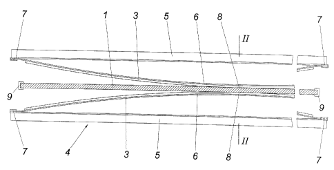
Fig. I shows an apparatus in accordance with the invention for applying a pro-
tective strip to a cathode plate in a schematic top view of the pressing jaws
of a
pressing tool, and
Fig. 2 shows a sectional view along line II-II in Fig. 1 on an enlarged scale.
DESCRIPTION OF THE PREFERRED EMBODIMENT
In order to protect a cathode plate I which is suspended with the help of a
car-
rying strip 2 in an electroplating bath for depositing a metal from an
electrolytic
fluid from corrosive attack by the electrolytic fluid in the region of the
bath level,
the cathode plate 1 is covered in the section of the bath level threatened by
corrosion on both sides of the plate with a protective strip 3 made of a
suitable
thermoplastic material, preferably with a copolymer polyolefin. For
preparation
purposes, the cathode plate 1 can be brushed in the region of the later protec-
tive strips 3 prior to its heating in order to clean the surface of the
cathode plate
1 in this region and to obtain on the other a surface structure which improves
the bonding with the protective strips 3.
The connection of the protective strips 3 with the cathode plate 1 occurs by
pressing the protective strips 3 against the respectively heated cathode plate
1,
CA 02580089 2007-03-12
-5-
with the protective strips 3 being molten against the surface facing the
cathode
plate 1, so that during the subsequent cooling a favorable bonding is obtained
when the inclusion of air pockets between the cathode plate 1 and the protec-
tive strips 3 can be prevented. This is managed with a pressing tool 4 which
comprises two press jaws 5 with leaf springs 6 bulging forwardly against the
cathode plate 1 for receiving the protective strips 3. Said leaf springs 6 are
held
on the press jaws 5 in guide shoes 7 to be displaceable lengthwise in order to
enable pressing flat the leaf springs 6 during the pressing travel.
When the press jaws 5 are applied from opposite sides against the cathode
plate 1, the protective strips 3 clamped on the bulging leaf springs 6 are
pressed at first in the apex region of the leaf spring bulging against the
heated
cathode plate 1, as is shown in Fig. 1. During the following press travel, the
protective strips 3 are pressed starting from said middle contact section 8
pro-
gressively lengthwise against the cathode plate 1 because the leaf springs 6
are increasingly pressed flatly in order to finally be held pressed against
the
cathode plate 1 over the entire length. After the cooling of the cathode plate
1,
preferably with the help of cooling plates, the cathode plate 1 can be removed
with the applied protective strips 3 from the pressing tool 4.
As is shown in Fig. 2, the leaf springs 6 can be profiled according to the
desired
cross section of the protective strips 3 in order to achieve a rounding of the
lon-
gitudinal edge in the region of the longitudinal sides of the protective
strips 3
facing the electrolytic bath during the pressing of said protective strips 3
against
the cathode plate 1. Such a plastic deformation is easily possible as a result
of
the heating of the protective strips 3 by the cathode plate 1.
It has been seen that a heating of the cathode plate to 175 C to 195 C is
suffi-
cient to melt on the protective strips 3. The pressing pressure is preferably
be-
tween 4 to 6 bar and is held for approximately 1 minute before the cathode
plate 1 is cooled via cooling plates to a stacking temperature.
= CA 02580089 2007-03-12
-6-
When the side edges of the cathode plate 1 are protected by edge strips 9
which are profiled in a U-shaped way, the pressing of the protective strips
against the cathode plate 1 which occurs progressively against the ends of the
protective strips 1 will also ensure an interlocking connection of the
protective
strips 3 to the edge strips 9 without having to fear any likelihood of
corrosion in
the connecting region for the cathode plate 1.