Language selection

Search

Patent 2593460 Summary

Third-party information liability

Some of the information on this Web page has been provided by external sources. The Government of Canada is not responsible for the accuracy, reliability or currency of the information supplied by external sources. Users wishing to rely upon this information should consult directly with the source of the information. Content provided by external sources is not subject to official languages, privacy and accessibility requirements.

Claims and Abstract availability

Any discrepancies in the text and image of the Claims and Abstract are due to differing posting times. Text of the Claims and Abstract are posted:

  • At the time the application is open to public inspection;
  • At the time of issue of the patent (grant).
(12) Patent: (11) CA 2593460
(54) English Title: METHOD OF AND APPARATUS FOR CONNECTING FLOATING COVERS
(54) French Title: PROCEDE ET EQUIPEMENT DE RACCORDEMENT DE COUVERCLES FLOTTANTS
Status: Granted
Bibliographic Data
(51) International Patent Classification (IPC):
  • F16B 1/00 (2006.01)
  • E04H 4/08 (2006.01)
  • F16B 5/00 (2006.01)
  • F16B 5/02 (2006.01)
(72) Inventors :
  • MILLS, J. ANDREW (Canada)
  • MACQUEEN, JASON J. R. (Canada)
(73) Owners :
  • LAYFIELD GEOSYNTHETICS & INDUSTRIAL FABRICS LTD. (Canada)
(71) Applicants :
  • LAYFIELD GEOSYNTHETICS & INDUSTRIAL FABRICS LTD. (Canada)
(74) Agent: WOODRUFF, NATHAN V.
(74) Associate agent:
(45) Issued: 2012-01-03
(22) Filed Date: 2007-07-04
(41) Open to Public Inspection: 2009-01-04
Examination requested: 2009-04-23
Availability of licence: N/A
(25) Language of filing: English

Patent Cooperation Treaty (PCT): No

(30) Application Priority Data: None

Abstracts

English Abstract

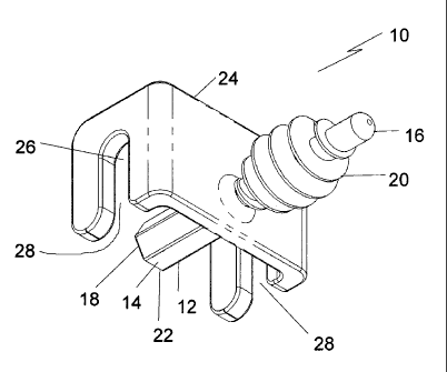
An apparatus for connecting pond covers, which includes a shaft having an exterior surface, a first end and a second end. An engagement profile is positioned on the exterior surface at a first end of the shaft. A cable guide is positioned in an intermediate position between the first end and the second end of the shaft, the cable guide being oriented transversely to the shaft. A cable is prevented from removal from the cable guide by the second end of the shaft.


French Abstract

Appareil servant à relier les couvercles de bassin. Il inclut un arbre possédant une surface extérieure, une première extrémité et une deuxième. Un profil d'engagement se trouve sur la surface extérieure à une première extrémité de l'arbre. Un guide-câble est placé dans une position intermédiaire entre la première et la deuxième extrémités de l'arbre, le guide-câble étant orienté de manière transversale par rapport à l'arbre. Le câble est empêché de sortir du guide-câble par la deuxième extrémité de l'arbre.

Claims

Note: Claims are shown in the official language in which they were submitted.


What is Claimed is:

1. An apparatus for connecting pond covers, comprising:
a shaft having an exterior surface, a first end, and a second end;
an engagement profile positioned on the exterior surface at the first end of
the shaft;
a cable guide positioned in an intermediate position between the first end and
the second
end of the shaft, the cable guide being oriented transversely to the shaft,
the cable guide having a
cable retention channel and a cable access slot, a cable being retained in the
cable retention
channel by the positioning of the second end of the shaft between the cable
retention channel and
the cable access slot.

2. The apparatus of Claim 1, wherein the engagement profile is a helical
thread.

3. The apparatus of Claim 2, wherein a rotational drive adaptor is positioned
at the second end of
the shaft.

4. The apparatus of Claim 1, wherein the engagement profile is a series of
parallel spaced ridges.
5. The apparatus of Claim 3, wherein the rotational drive adaptor is a
polygonal drive head.

6. The apparatus of Claim 5, wherein the rotational drive adaptor is a
hexagonal drive head.
7. An apparatus for connecting pond covers, comprising:
a shaft having an exterior surface, a first end, and a second end;
an engagement profile in the form of helical thread positioned on the exterior
surface at
the first end of the shaft;
a hexagonal head rotational drive adaptor positioned at the second end of the
shaft;
a cable guide positioned in an intermediate position between the first end and
the second
end of the shaft, the cable guide being oriented transversely to the shaft,
the cable guide having a
cable retention channel and a cable access slot, a cable being retained in the
cable retention


6
channel by the positioning of the second end of the shaft between the cable
retention channel and
the cable access slot.

8. A method of connecting pond covers, comprising:
providing two pond covers, each pond cover having grommets positioned along a
peripheral edge which define pond cover attachment openings; and
providing apparatus for connecting the two pond covers, the apparatus
comprising:
a shaft having an exterior surface, a first end and a second end;
an engagement profile positioned on the exterior surface at the first end of
the shaft; and
a cable guide positioned in an intermediate position between the first end
and the second end of the shaft, the cable guide being oriented transversely
to the shaft, a cable
being prevented from removal from the cable guide by the second end of the
shaft;
overlapping the peripheral edge of the two pond covers with the pond cover
attachment
openings of the two pond covers axially aligned; and
inserting the first end of the shaft of the apparatus into one of the pond
cover attachment
openings with the engagement profile preventing removal of the shaft from the
pond cover
attachment openings.

9. The method of Claim 8, the engagement profile being a helical thread, a
rotational drive
adaptor being positioned at the second end of the shaft and the step of
inserting the first end of
the shaft into one of the pond cover attachment openings being performed using
a power drill.

Description

Note: Descriptions are shown in the official language in which they were submitted.


CA 02593460 2007-07-04
TITLE:
Method of and apparatus for connecting floating covers.
FIELD
The present invention relates to a method and associated apparatus which can
be used
to connect floating covers.

BACKGROUND
United States Patent 5,400,549 (Morgan) discloses a pond cover which consists
of a
plurality of cover panel units connected together with cable connectors.

SUMMARY
According to one aspect there is provided an apparatus for connecting floating
covers,
which includes a shaft having an exterior surface, a first end and a second
end. An
engagement profile is positioned on the exterior surface at a first end of the
shaft. A cable
guide is positioned in an intermediate position between the first end and the
second end of the
shaft, the cable guide being oriented transversely to the shaft. A cable is
prevented from
removal from the cable guide by the second end of the shaft.

According to another aspect there is provided a method of connecting floating
covers.
A first step involves providing two floating covers having grommets positioned
along a
peripheral edge which define floating cover attachment openings, along with
the above
described apparatus for connecting floating covers. A second step involves
overlapping the
peripheral edge of the two floating covers with the floating cover attachment
openings of the
two floating covers axially aligned. A third step involves inserting the first
end of the shaft of
one of the apparatus for connecting floating covers into one of the floating
cover attachment
openings, with the engagement profile preventing removal of the shaft from the
floating cover
attachment openings. (Note that these covers could be installed on ponds and
as tank covers).
BRIEF DESCRIPTION OF THE DRAWINGS
These and other features will become more apparent from the following
description in
which reference is made to the appended drawings, the drawings are for the
purpose of
illustration only and are not intended to in any way limit the scope of the
invention to the


CA 02593460 2007-07-04
2

particular embodiment or embodiments shown, wherein:
FIG. 1 is a perspective view of an apparatus for connecting floating covers.
FIG. 2 is a front elevation view of the apparatus for connecting floating
covers
illustrated in FIG. 1.
FIG. 3 is a left side elevation view of the apparatus for connecting floating
covers
illustrated in FIG. 1.
FIG. 4 is a right side elevation view of the apparatus for connecting floating
covers
illustrated in FIG. 1.
FIG. 5 is a rear elevation view of the apparatus for connecting floating
covers
illustrated in FIG. 1.
FIG. 6 is a top plan view of the apparatus for connecting floating covers
illustrated in
FIG.1.
FIG. 7 is a bottom plan view of the apparatus for connecting floating covers
illustrated in FIG. 1.
FIG. 8 is a side elevation view, in section, of two floating covers connected
with one
of the apparatus for connecting floating covers illustrated in FIG. 1.
FIG. 9 is a side elevation view of the apparatus for connecting floating
covers
illustrated in FIG. 1, with an alternative form of engagement profile.
FIG. 10 is a top perspective view of floating covers connected with the
apparatus for
connecting floating covers illustrated in FIG. 1.

DETAILED DESCRIPTION
An apparatus for connecting floating covers generally identified by reference
numeral
10, will now be described with reference to FIG. 1 through 10.

Structure and Relationship of Parts:
Referring to FIG. 1, apparatus 10 has a shaft 12 having an exterior surface
14, a first
end 16 and a second end 18. Referring to FIG. 2 and FIG. 3, an engagement
profile 20, in
the form of helical thread, is positioned on the exterior surface 14 at first
end 16 of shaft.
Referring to FIG. 1 and FIG. 5, a hexagonal head rotational drive adaptor 22
is positioned at
second end 18 of shaft 12. Referring to FIG. 1 and FIG. 7, a cable guide 24 is
positioned in


CA 02593460 2007-07-04
3

an intermediate position between first end 16 and second end 18 of shaft 12.
Cable guide 24 is
oriented transversely to shaft 12 and has a cable retention channel 26 and a
cable access slot
28. A cable may be retained in cable retention channel 26 by the positioning
of second end
18 of shaft 12 between cable retention channel 26 and cable access slot 28,
this is illustrated
in FIG. 10 in relation to cable 30.

Operation:
Referring to FIG. 8, a method of connecting floating covers 32 is illustrated.
Floating
covers 32 may be used as covers for ponds, pools, tanks, etc. While the
description below
refers to pond covers, it will be understood that it may also be used in other
situations. At
least two pond covers 32 are required. Each pond cover 32 has holes 34
positioned along a
peripheral edge 36. Holes 34 define pond cover attachment openings 38 and
provide for
apparatus 10 to connect the pond covers 32. Peripheral edge 36 of two pond
covers 32 are
overlapped with the pond cover attachment openings 38 axially aligned. To
connect pond
covers 32 insert first end 16 of shaft 12 of apparatus 10 into one of the pond
cover attachment
openings 38. Engagement profile 20 engages with holes 34 to ensure that pond
covers 32
remained aligned and connected at peripheral edge 36. This enables several
pond covers 32
to be connected to create a pond cover sufficient to cover the size of pond.

Referring to FIG. 4 and FIG. 8, as engagement profile 20 is helical, a power
drill (not
shown) is attached to rotational drive adaptor 22 which is positioned at
second end 18 of shaft
12, and can be seen in FIG. 5. The power drill provides the means for
engagement profile 20
and holes 34 to interact and secure the two pond covers 32 together. Referring
to FIG. 10,
cable 30 is secured in cable guide 24 at second end 18 of shaft 12.
Advantages:
The use of the above described method allows the pool covers to be rapidly
connected. More importantly, portions of the pool covers can be just as
rapidly disconnected
when access is required to perform servicing. With the prior art, the
separation of the pond
covers to enable servicing to be performed and the reconnection of the pond
covers after
servicing has proven to be a major undertaking.


CA 02593460 2007-07-04
4

In addition, current cover fastening methods require at least some access to
both sides
of the cover panel to install or removed the panels, this can be difficult due
to panel size (a
typical size may be 8' x 48'), or panel location, if floating on a liquid
surface. However,
apparatus can be fully installed or removed from a single side of the cover
(typically the dry
side).

Variations:
Although apparatus 10 is shown with a helical engagement profile 20 that works
with
rotational drive adaptor 22 in FIG. 1 through 8, it will be appreciated that
other engagement
profiles could be made to work. There are too many alterative engagements to
illustrate them
all. Referring to FIG. 9, another viable engagement profile 20 could consist
of a series of
parallel spaced ridges.

In this patent document, the word "comprising" is used in its non-limiting
sense to
mean that items following the word are included, but items not specifically
mentioned are not
excluded. A reference to an element by the indefinite article "a" does not
exclude the
possibility that more than one of the element is present, unless the context
clearly requires that
there be one and only one of the elements.
It will be apparent to one skilled in the art that modifications may be made
to the
illustrated embodiments without departing from scope of the Claims.

Representative Drawing
A single figure which represents the drawing illustrating the invention.
Administrative Status

For a clearer understanding of the status of the application/patent presented on this page, the site Disclaimer , as well as the definitions for Patent , Administrative Status , Maintenance Fee  and Payment History  should be consulted.

Administrative Status

Title Date
Forecasted Issue Date 2012-01-03
(22) Filed 2007-07-04
(41) Open to Public Inspection 2009-01-04
Examination Requested 2009-04-23
(45) Issued 2012-01-03

Abandonment History

There is no abandonment history.

Maintenance Fee

Last Payment of $624.00 was received on 2024-05-06


 Upcoming maintenance fee amounts

Description Date Amount
Next Payment if standard fee 2025-07-04 $624.00
Next Payment if small entity fee 2025-07-04 $253.00

Note : If the full payment has not been received on or before the date indicated, a further fee may be required which may be one of the following

  • the reinstatement fee;
  • the late payment fee; or
  • additional fee to reverse deemed expiry.

Patent fees are adjusted on the 1st of January every year. The amounts above are the current amounts if received by December 31 of the current year.
Please refer to the CIPO Patent Fees web page to see all current fee amounts.

Payment History

Fee Type Anniversary Year Due Date Amount Paid Paid Date
Application Fee $400.00 2007-07-04
Request for Examination $800.00 2009-04-23
Maintenance Fee - Application - New Act 2 2009-07-06 $100.00 2009-04-23
Registration of a document - section 124 $100.00 2009-09-28
Expired 2019 - The completion of the application $200.00 2009-09-28
Maintenance Fee - Application - New Act 3 2010-07-05 $100.00 2010-04-28
Maintenance Fee - Application - New Act 4 2011-07-04 $100.00 2011-05-04
Final Fee $300.00 2011-10-19
Maintenance Fee - Patent - New Act 5 2012-07-04 $200.00 2012-05-04
Maintenance Fee - Patent - New Act 6 2013-07-04 $200.00 2013-04-30
Maintenance Fee - Patent - New Act 7 2014-07-04 $200.00 2014-05-28
Maintenance Fee - Patent - New Act 8 2015-07-06 $200.00 2015-06-23
Maintenance Fee - Patent - New Act 9 2016-07-04 $200.00 2016-06-29
Maintenance Fee - Patent - New Act 10 2017-07-04 $250.00 2017-05-24
Maintenance Fee - Patent - New Act 11 2018-07-04 $250.00 2018-06-19
Maintenance Fee - Patent - New Act 12 2019-07-04 $250.00 2019-07-04
Maintenance Fee - Patent - New Act 13 2020-07-06 $250.00 2020-05-29
Maintenance Fee - Patent - New Act 14 2021-07-05 $255.00 2021-05-03
Maintenance Fee - Patent - New Act 15 2022-07-04 $458.08 2022-07-04
Maintenance Fee - Patent - New Act 16 2023-07-04 $473.65 2023-04-13
Maintenance Fee - Patent - New Act 17 2024-07-04 $624.00 2024-05-06
Owners on Record

Note: Records showing the ownership history in alphabetical order.

Current Owners on Record
LAYFIELD GEOSYNTHETICS & INDUSTRIAL FABRICS LTD.
Past Owners on Record
MACQUEEN, JASON J. R.
MILLS, J. ANDREW
Past Owners that do not appear in the "Owners on Record" listing will appear in other documentation within the application.
Documents

To view selected files, please enter reCAPTCHA code :


To view images, click a link in the Document Description column. To download the documents, select one or more checkboxes in the first column and then click the "Download Selected in PDF format (Zip Archive)" or the "Download Selected as Single PDF" button.

List of published and non-published patent-specific documents on the CPD .

If you have any difficulty accessing content, you can call the Client Service Centre at 1-866-997-1936 or send them an e-mail at CIPO Client Service Centre.


Document
Description 
Date
(yyyy-mm-dd) 
Number of pages   Size of Image (KB) 
Maintenance Fee Payment 2020-05-29 1 33
Maintenance Fee Payment 2022-07-04 1 33
Abstract 2007-07-04 1 11
Description 2007-07-04 4 153
Claims 2007-07-04 2 68
Drawings 2007-07-04 6 87
Representative Drawing 2008-11-17 1 10
Cover Page 2008-12-17 1 38
Drawings 2009-06-19 6 83
Claims 2011-03-30 2 72
Cover Page 2011-12-02 1 37
Representative Drawing 2011-12-19 1 10
Correspondence 2011-04-27 1 11
Correspondence 2011-04-27 1 19
Correspondence 2010-01-07 1 15
Assignment 2007-07-04 2 74
Correspondence 2007-08-08 1 23
Correspondence 2007-08-08 1 64
Prosecution-Amendment 2007-08-20 1 28
Correspondence 2009-03-05 1 39
Prosecution-Amendment 2009-04-23 1 34
Fees 2009-04-23 1 34
Correspondence 2009-05-01 1 81
Prosecution-Amendment 2009-06-19 4 103
Assignment 2009-09-28 1 42
Correspondence 2009-09-28 1 43
Correspondence 2009-10-16 1 14
Correspondence 2009-10-16 1 22
Assignment 2009-11-03 4 129
Correspondence 2010-01-07 2 44
Fees 2010-04-28 1 200
Prosecution-Amendment 2011-02-22 3 99
Prosecution-Amendment 2011-03-30 7 192
Correspondence 2011-03-31 3 157
Correspondence 2011-10-19 1 34
Fees 2016-06-29 1 33