Sélection de la langue

Search

Sommaire du brevet 2593460 

Énoncé de désistement de responsabilité concernant l'information provenant de tiers

Une partie des informations de ce site Web a été fournie par des sources externes. Le gouvernement du Canada n'assume aucune responsabilité concernant la précision, l'actualité ou la fiabilité des informations fournies par les sources externes. Les utilisateurs qui désirent employer cette information devraient consulter directement la source des informations. Le contenu fourni par les sources externes n'est pas assujetti aux exigences sur les langues officielles, la protection des renseignements personnels et l'accessibilité.

Disponibilité de l'Abrégé et des Revendications

L'apparition de différences dans le texte et l'image des Revendications et de l'Abrégé dépend du moment auquel le document est publié. Les textes des Revendications et de l'Abrégé sont affichés :

  • lorsque la demande peut être examinée par le public;
  • lorsque le brevet est émis (délivrance).
(12) Brevet: (11) CA 2593460
(54) Titre français: PROCEDE ET EQUIPEMENT DE RACCORDEMENT DE COUVERCLES FLOTTANTS
(54) Titre anglais: METHOD OF AND APPARATUS FOR CONNECTING FLOATING COVERS
Statut: Octroyé
Données bibliographiques
(51) Classification internationale des brevets (CIB):
  • F16B 1/00 (2006.01)
  • E04H 4/08 (2006.01)
  • F16B 5/00 (2006.01)
  • F16B 5/02 (2006.01)
(72) Inventeurs :
  • MILLS, J. ANDREW (Canada)
  • MACQUEEN, JASON J. R. (Canada)
(73) Titulaires :
  • LAYFIELD GEOSYNTHETICS & INDUSTRIAL FABRICS LTD. (Canada)
(71) Demandeurs :
  • LAYFIELD GEOSYNTHETICS & INDUSTRIAL FABRICS LTD. (Canada)
(74) Agent: WOODRUFF, NATHAN V.
(74) Co-agent:
(45) Délivré: 2012-01-03
(22) Date de dépôt: 2007-07-04
(41) Mise à la disponibilité du public: 2009-01-04
Requête d'examen: 2009-04-23
Licence disponible: S.O.
(25) Langue des documents déposés: Anglais

Traité de coopération en matière de brevets (PCT): Non

(30) Données de priorité de la demande: S.O.

Abrégés

Abrégé français

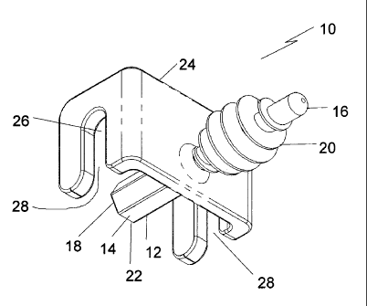
Appareil servant à relier les couvercles de bassin. Il inclut un arbre possédant une surface extérieure, une première extrémité et une deuxième. Un profil d'engagement se trouve sur la surface extérieure à une première extrémité de l'arbre. Un guide-câble est placé dans une position intermédiaire entre la première et la deuxième extrémités de l'arbre, le guide-câble étant orienté de manière transversale par rapport à l'arbre. Le câble est empêché de sortir du guide-câble par la deuxième extrémité de l'arbre.


Abrégé anglais

An apparatus for connecting pond covers, which includes a shaft having an exterior surface, a first end and a second end. An engagement profile is positioned on the exterior surface at a first end of the shaft. A cable guide is positioned in an intermediate position between the first end and the second end of the shaft, the cable guide being oriented transversely to the shaft. A cable is prevented from removal from the cable guide by the second end of the shaft.

Revendications

Note : Les revendications sont présentées dans la langue officielle dans laquelle elles ont été soumises.


What is Claimed is:

1. An apparatus for connecting pond covers, comprising:
a shaft having an exterior surface, a first end, and a second end;
an engagement profile positioned on the exterior surface at the first end of
the shaft;
a cable guide positioned in an intermediate position between the first end and
the second
end of the shaft, the cable guide being oriented transversely to the shaft,
the cable guide having a
cable retention channel and a cable access slot, a cable being retained in the
cable retention
channel by the positioning of the second end of the shaft between the cable
retention channel and
the cable access slot.

2. The apparatus of Claim 1, wherein the engagement profile is a helical
thread.

3. The apparatus of Claim 2, wherein a rotational drive adaptor is positioned
at the second end of
the shaft.

4. The apparatus of Claim 1, wherein the engagement profile is a series of
parallel spaced ridges.
5. The apparatus of Claim 3, wherein the rotational drive adaptor is a
polygonal drive head.

6. The apparatus of Claim 5, wherein the rotational drive adaptor is a
hexagonal drive head.
7. An apparatus for connecting pond covers, comprising:
a shaft having an exterior surface, a first end, and a second end;
an engagement profile in the form of helical thread positioned on the exterior
surface at
the first end of the shaft;
a hexagonal head rotational drive adaptor positioned at the second end of the
shaft;
a cable guide positioned in an intermediate position between the first end and
the second
end of the shaft, the cable guide being oriented transversely to the shaft,
the cable guide having a
cable retention channel and a cable access slot, a cable being retained in the
cable retention


6
channel by the positioning of the second end of the shaft between the cable
retention channel and
the cable access slot.

8. A method of connecting pond covers, comprising:
providing two pond covers, each pond cover having grommets positioned along a
peripheral edge which define pond cover attachment openings; and
providing apparatus for connecting the two pond covers, the apparatus
comprising:
a shaft having an exterior surface, a first end and a second end;
an engagement profile positioned on the exterior surface at the first end of
the shaft; and
a cable guide positioned in an intermediate position between the first end
and the second end of the shaft, the cable guide being oriented transversely
to the shaft, a cable
being prevented from removal from the cable guide by the second end of the
shaft;
overlapping the peripheral edge of the two pond covers with the pond cover
attachment
openings of the two pond covers axially aligned; and
inserting the first end of the shaft of the apparatus into one of the pond
cover attachment
openings with the engagement profile preventing removal of the shaft from the
pond cover
attachment openings.

9. The method of Claim 8, the engagement profile being a helical thread, a
rotational drive
adaptor being positioned at the second end of the shaft and the step of
inserting the first end of
the shaft into one of the pond cover attachment openings being performed using
a power drill.

Description

Note : Les descriptions sont présentées dans la langue officielle dans laquelle elles ont été soumises.


CA 02593460 2007-07-04
TITLE:
Method of and apparatus for connecting floating covers.
FIELD
The present invention relates to a method and associated apparatus which can
be used
to connect floating covers.

BACKGROUND
United States Patent 5,400,549 (Morgan) discloses a pond cover which consists
of a
plurality of cover panel units connected together with cable connectors.

SUMMARY
According to one aspect there is provided an apparatus for connecting floating
covers,
which includes a shaft having an exterior surface, a first end and a second
end. An
engagement profile is positioned on the exterior surface at a first end of the
shaft. A cable
guide is positioned in an intermediate position between the first end and the
second end of the
shaft, the cable guide being oriented transversely to the shaft. A cable is
prevented from
removal from the cable guide by the second end of the shaft.

According to another aspect there is provided a method of connecting floating
covers.
A first step involves providing two floating covers having grommets positioned
along a
peripheral edge which define floating cover attachment openings, along with
the above
described apparatus for connecting floating covers. A second step involves
overlapping the
peripheral edge of the two floating covers with the floating cover attachment
openings of the
two floating covers axially aligned. A third step involves inserting the first
end of the shaft of
one of the apparatus for connecting floating covers into one of the floating
cover attachment
openings, with the engagement profile preventing removal of the shaft from the
floating cover
attachment openings. (Note that these covers could be installed on ponds and
as tank covers).
BRIEF DESCRIPTION OF THE DRAWINGS
These and other features will become more apparent from the following
description in
which reference is made to the appended drawings, the drawings are for the
purpose of
illustration only and are not intended to in any way limit the scope of the
invention to the


CA 02593460 2007-07-04
2

particular embodiment or embodiments shown, wherein:
FIG. 1 is a perspective view of an apparatus for connecting floating covers.
FIG. 2 is a front elevation view of the apparatus for connecting floating
covers
illustrated in FIG. 1.
FIG. 3 is a left side elevation view of the apparatus for connecting floating
covers
illustrated in FIG. 1.
FIG. 4 is a right side elevation view of the apparatus for connecting floating
covers
illustrated in FIG. 1.
FIG. 5 is a rear elevation view of the apparatus for connecting floating
covers
illustrated in FIG. 1.
FIG. 6 is a top plan view of the apparatus for connecting floating covers
illustrated in
FIG.1.
FIG. 7 is a bottom plan view of the apparatus for connecting floating covers
illustrated in FIG. 1.
FIG. 8 is a side elevation view, in section, of two floating covers connected
with one
of the apparatus for connecting floating covers illustrated in FIG. 1.
FIG. 9 is a side elevation view of the apparatus for connecting floating
covers
illustrated in FIG. 1, with an alternative form of engagement profile.
FIG. 10 is a top perspective view of floating covers connected with the
apparatus for
connecting floating covers illustrated in FIG. 1.

DETAILED DESCRIPTION
An apparatus for connecting floating covers generally identified by reference
numeral
10, will now be described with reference to FIG. 1 through 10.

Structure and Relationship of Parts:
Referring to FIG. 1, apparatus 10 has a shaft 12 having an exterior surface
14, a first
end 16 and a second end 18. Referring to FIG. 2 and FIG. 3, an engagement
profile 20, in
the form of helical thread, is positioned on the exterior surface 14 at first
end 16 of shaft.
Referring to FIG. 1 and FIG. 5, a hexagonal head rotational drive adaptor 22
is positioned at
second end 18 of shaft 12. Referring to FIG. 1 and FIG. 7, a cable guide 24 is
positioned in


CA 02593460 2007-07-04
3

an intermediate position between first end 16 and second end 18 of shaft 12.
Cable guide 24 is
oriented transversely to shaft 12 and has a cable retention channel 26 and a
cable access slot
28. A cable may be retained in cable retention channel 26 by the positioning
of second end
18 of shaft 12 between cable retention channel 26 and cable access slot 28,
this is illustrated
in FIG. 10 in relation to cable 30.

Operation:
Referring to FIG. 8, a method of connecting floating covers 32 is illustrated.
Floating
covers 32 may be used as covers for ponds, pools, tanks, etc. While the
description below
refers to pond covers, it will be understood that it may also be used in other
situations. At
least two pond covers 32 are required. Each pond cover 32 has holes 34
positioned along a
peripheral edge 36. Holes 34 define pond cover attachment openings 38 and
provide for
apparatus 10 to connect the pond covers 32. Peripheral edge 36 of two pond
covers 32 are
overlapped with the pond cover attachment openings 38 axially aligned. To
connect pond
covers 32 insert first end 16 of shaft 12 of apparatus 10 into one of the pond
cover attachment
openings 38. Engagement profile 20 engages with holes 34 to ensure that pond
covers 32
remained aligned and connected at peripheral edge 36. This enables several
pond covers 32
to be connected to create a pond cover sufficient to cover the size of pond.

Referring to FIG. 4 and FIG. 8, as engagement profile 20 is helical, a power
drill (not
shown) is attached to rotational drive adaptor 22 which is positioned at
second end 18 of shaft
12, and can be seen in FIG. 5. The power drill provides the means for
engagement profile 20
and holes 34 to interact and secure the two pond covers 32 together. Referring
to FIG. 10,
cable 30 is secured in cable guide 24 at second end 18 of shaft 12.
Advantages:
The use of the above described method allows the pool covers to be rapidly
connected. More importantly, portions of the pool covers can be just as
rapidly disconnected
when access is required to perform servicing. With the prior art, the
separation of the pond
covers to enable servicing to be performed and the reconnection of the pond
covers after
servicing has proven to be a major undertaking.


CA 02593460 2007-07-04
4

In addition, current cover fastening methods require at least some access to
both sides
of the cover panel to install or removed the panels, this can be difficult due
to panel size (a
typical size may be 8' x 48'), or panel location, if floating on a liquid
surface. However,
apparatus can be fully installed or removed from a single side of the cover
(typically the dry
side).

Variations:
Although apparatus 10 is shown with a helical engagement profile 20 that works
with
rotational drive adaptor 22 in FIG. 1 through 8, it will be appreciated that
other engagement
profiles could be made to work. There are too many alterative engagements to
illustrate them
all. Referring to FIG. 9, another viable engagement profile 20 could consist
of a series of
parallel spaced ridges.

In this patent document, the word "comprising" is used in its non-limiting
sense to
mean that items following the word are included, but items not specifically
mentioned are not
excluded. A reference to an element by the indefinite article "a" does not
exclude the
possibility that more than one of the element is present, unless the context
clearly requires that
there be one and only one of the elements.
It will be apparent to one skilled in the art that modifications may be made
to the
illustrated embodiments without departing from scope of the Claims.

Dessin représentatif
Une figure unique qui représente un dessin illustrant l'invention.
États administratifs

Pour une meilleure compréhension de l'état de la demande ou brevet qui figure sur cette page, la rubrique Mise en garde , et les descriptions de Brevet , États administratifs , Taxes périodiques et Historique des paiements devraient être consultées.

États administratifs

Titre Date
Date de délivrance prévu 2012-01-03
(22) Dépôt 2007-07-04
(41) Mise à la disponibilité du public 2009-01-04
Requête d'examen 2009-04-23
(45) Délivré 2012-01-03

Historique d'abandonnement

Il n'y a pas d'historique d'abandonnement

Taxes périodiques

Dernier paiement au montant de 624,00 $ a été reçu le 2024-05-06


 Montants des taxes pour le maintien en état à venir

Description Date Montant
Prochain paiement si taxe générale 2025-07-04 624,00 $
Prochain paiement si taxe applicable aux petites entités 2025-07-04 253,00 $

Avis : Si le paiement en totalité n'a pas été reçu au plus tard à la date indiquée, une taxe supplémentaire peut être imposée, soit une des taxes suivantes :

  • taxe de rétablissement ;
  • taxe pour paiement en souffrance ; ou
  • taxe additionnelle pour le renversement d'une péremption réputée.

Les taxes sur les brevets sont ajustées au 1er janvier de chaque année. Les montants ci-dessus sont les montants actuels s'ils sont reçus au plus tard le 31 décembre de l'année en cours.
Veuillez vous référer à la page web des taxes sur les brevets de l'OPIC pour voir tous les montants actuels des taxes.

Historique des paiements

Type de taxes Anniversaire Échéance Montant payé Date payée
Le dépôt d'une demande de brevet 400,00 $ 2007-07-04
Requête d'examen 800,00 $ 2009-04-23
Taxe de maintien en état - Demande - nouvelle loi 2 2009-07-06 100,00 $ 2009-04-23
Enregistrement de documents 100,00 $ 2009-09-28
Expiré 2019 - Le complètement de la demande 200,00 $ 2009-09-28
Taxe de maintien en état - Demande - nouvelle loi 3 2010-07-05 100,00 $ 2010-04-28
Taxe de maintien en état - Demande - nouvelle loi 4 2011-07-04 100,00 $ 2011-05-04
Taxe finale 300,00 $ 2011-10-19
Taxe de maintien en état - brevet - nouvelle loi 5 2012-07-04 200,00 $ 2012-05-04
Taxe de maintien en état - brevet - nouvelle loi 6 2013-07-04 200,00 $ 2013-04-30
Taxe de maintien en état - brevet - nouvelle loi 7 2014-07-04 200,00 $ 2014-05-28
Taxe de maintien en état - brevet - nouvelle loi 8 2015-07-06 200,00 $ 2015-06-23
Taxe de maintien en état - brevet - nouvelle loi 9 2016-07-04 200,00 $ 2016-06-29
Taxe de maintien en état - brevet - nouvelle loi 10 2017-07-04 250,00 $ 2017-05-24
Taxe de maintien en état - brevet - nouvelle loi 11 2018-07-04 250,00 $ 2018-06-19
Taxe de maintien en état - brevet - nouvelle loi 12 2019-07-04 250,00 $ 2019-07-04
Taxe de maintien en état - brevet - nouvelle loi 13 2020-07-06 250,00 $ 2020-05-29
Taxe de maintien en état - brevet - nouvelle loi 14 2021-07-05 255,00 $ 2021-05-03
Taxe de maintien en état - brevet - nouvelle loi 15 2022-07-04 458,08 $ 2022-07-04
Taxe de maintien en état - brevet - nouvelle loi 16 2023-07-04 473,65 $ 2023-04-13
Taxe de maintien en état - brevet - nouvelle loi 17 2024-07-04 624,00 $ 2024-05-06
Titulaires au dossier

Les titulaires actuels et antérieures au dossier sont affichés en ordre alphabétique.

Titulaires actuels au dossier
LAYFIELD GEOSYNTHETICS & INDUSTRIAL FABRICS LTD.
Titulaires antérieures au dossier
MACQUEEN, JASON J. R.
MILLS, J. ANDREW
Les propriétaires antérieurs qui ne figurent pas dans la liste des « Propriétaires au dossier » apparaîtront dans d'autres documents au dossier.
Documents

Pour visionner les fichiers sélectionnés, entrer le code reCAPTCHA :


Pour visualiser une image, cliquer sur un lien dans la colonne description du document. Pour télécharger l'image (les images), cliquer l'une ou plusieurs cases à cocher dans la première colonne et ensuite cliquer sur le bouton "Télécharger sélection en format PDF (archive Zip)" ou le bouton "Télécharger sélection (en un fichier PDF fusionné)".

Liste des documents de brevet publiés et non publiés sur la BDBC .

Si vous avez des difficultés à accéder au contenu, veuillez communiquer avec le Centre de services à la clientèle au 1-866-997-1936, ou envoyer un courriel au Centre de service à la clientèle de l'OPIC.


Description du
Document 
Date
(yyyy-mm-dd) 
Nombre de pages   Taille de l'image (Ko) 
Paiement de taxe périodique 2020-05-29 1 33
Paiement de taxe périodique 2022-07-04 1 33
Abrégé 2007-07-04 1 11
Description 2007-07-04 4 153
Revendications 2007-07-04 2 68
Dessins 2007-07-04 6 87
Dessins représentatifs 2008-11-17 1 10
Page couverture 2008-12-17 1 38
Dessins 2009-06-19 6 83
Revendications 2011-03-30 2 72
Page couverture 2011-12-02 1 37
Dessins représentatifs 2011-12-19 1 10
Correspondance 2011-04-27 1 11
Correspondance 2011-04-27 1 19
Correspondance 2010-01-07 1 15
Cession 2007-07-04 2 74
Correspondance 2007-08-08 1 23
Correspondance 2007-08-08 1 64
Poursuite-Amendment 2007-08-20 1 28
Correspondance 2009-03-05 1 39
Poursuite-Amendment 2009-04-23 1 34
Taxes 2009-04-23 1 34
Correspondance 2009-05-01 1 81
Poursuite-Amendment 2009-06-19 4 103
Cession 2009-09-28 1 42
Correspondance 2009-09-28 1 43
Correspondance 2009-10-16 1 14
Correspondance 2009-10-16 1 22
Cession 2009-11-03 4 129
Correspondance 2010-01-07 2 44
Taxes 2010-04-28 1 200
Poursuite-Amendment 2011-02-22 3 99
Poursuite-Amendment 2011-03-30 7 192
Correspondance 2011-03-31 3 157
Correspondance 2011-10-19 1 34
Taxes 2016-06-29 1 33