Language selection

Search

Patent 2596418 Summary

Third-party information liability

Some of the information on this Web page has been provided by external sources. The Government of Canada is not responsible for the accuracy, reliability or currency of the information supplied by external sources. Users wishing to rely upon this information should consult directly with the source of the information. Content provided by external sources is not subject to official languages, privacy and accessibility requirements.

Claims and Abstract availability

Any discrepancies in the text and image of the Claims and Abstract are due to differing posting times. Text of the Claims and Abstract are posted:

  • At the time the application is open to public inspection;
  • At the time of issue of the patent (grant).
(12) Patent Application: (11) CA 2596418
(54) English Title: PLANAR-LIGHTING ASSEMBLY WITH UNIFORMLY LIGHT EMITTING FRONT SURFACE AND EDGES
(54) French Title: AJUSTEMENT D'ECLAIREMENT
Status: Dead
Bibliographic Data
(51) International Patent Classification (IPC):
  • G02B 6/00 (2006.01)
  • F21V 8/00 (2006.01)
(72) Inventors :
  • SKIBA, KRZYSTOF (Poland)
(73) Owners :
  • SKOFF SPOLKA Z O.O. (Poland)
(71) Applicants :
  • SKOFF SPOLKA Z O.O. (Poland)
(74) Agent: ROBIC
(74) Associate agent:
(45) Issued:
(86) PCT Filing Date: 2006-01-31
(87) Open to Public Inspection: 2006-08-10
Examination requested: 2011-01-31
Availability of licence: N/A
(25) Language of filing: English

Patent Cooperation Treaty (PCT): Yes
(86) PCT Filing Number: PCT/PL2006/000008
(87) International Publication Number: WO2006/083188
(85) National Entry: 2007-07-30

(30) Application Priority Data:
Application No. Country/Territory Date
P372550 Poland 2005-02-02

Abstracts

English Abstract


The object of the invention is the lighting fitting using LED-based source of
C light, applied for constructing functional frames, backlighting stair treads
and stair risers, furniture shelves, backlighting current connectors and
lighting traffic routes in buildings and structures. The lighting fitting is
supplied by an electrical system and it has a casing (1) with one side open
with a source of light (2) placed inside it. On the side of the casing (1)
opening, there is an optical fibre element (4) in the form of a shaped plate
whose at least two edges (3) and (7) transmit the luminous flux, with one on
the side of the light source (2), similarly as the front wall (5) of the
optical fibre element (4), while the back wall (6) of the optical fibre
element (4) is partly or wholly matted or covered with a light reflecting
material or fluorescent material.


French Abstract

L'objet de l'invention est l'ajustement d'éclairement utilisant une source à base de diodes LED de lumière C, appliquée pour construire des cadres fonctionnels, des marches et des contremarches d'escalier, des étagères de mobilier, des connecteurs de courant d'éclairage par l'arrière et des chemins d'éclairement de circulation dans des bâtiments et des structures. L'ajustement d'éclairement est fourni par un système électrique et il comporte un boîtier (1) présentant un flanc ouvert, comportant une source lumineuse (2) placée à l'intérieur. Sur le côté de l'ouverture du boîtier (1), il y a un élément de fibre optique (4) sous la forme d'une plaque façonnée dont au moins deux bords (3) et (7) transmettent le flux lumineux, l'un se trouvant du côté de la source lumineuse (2), de manière similaire à la paroi avant (5) de l'élément de fibre optique (4), alors que la paroi arrière (6) de l'élément de fibre optique (4) est partiellement ou totalement matée ou couverte d'un matériau de réflexion de la lumière ou d'un matériau fluorescent.

Claims

Note: Claims are shown in the official language in which they were submitted.


4


Claims

1. The lighting fitting, supplied by an electrical system, characterised by
the
fact that it has a casing (1) with one side open with a source of light (2)
placed inside it and, on the side of the casing (1) opening, there is an
optical fibre element (4) in the form of a shaped plate, preferably with two
parallel surfaces forming the front wall (5) and the back wall (6), whose at
least two edges (3) and (7) transmit the luminous flux, with one on the side
of the light source (2), similarly as the front wall (5) of the optical fibre
element (4), while the back wall (6) of the optical fibre element (4) is
partly
or wholly matted or covered with a light reflecting material or fluorescent
material.


2. The lighting fitting, according to Claim 1, characterised by the fact that
the edge (7) of the optical fibre element (4) is perpendicular, diagonal,
semicircular or shape-ended in relation to the back wall (6) of the optical
fibre element (4).


Description

Note: Descriptions are shown in the official language in which they were submitted.


CA 02596418 2007-07-30
WO 2006/083188 PCT/PL2006/000008
LIGHTING FITTING

The object of the invention is the lighting fitting using LED-based source of
light, applied for constructing functional frames, backlighting stair treads
and stair
risers, furniture shelves, backlighting current connectors and lighting
traffic routes
in buildings and structures.

There is known a Polish patent application no. P-364017 for a lighting clip
fixed around an edge of a transparent or semi-transparent panel in a removable
or
permanent way and supplied by an electric power system. The clip is in the
form of
a section, with at least one open side, consisted of clamping arms connected
with a
connector and provided with at least one source of light from the inside. The
section is in the form of a self-supporting elastic shape, with at least one
open side,
built of clamping arms of different length, where one of the arms is diagonal
to the
external panel surface or the section is in the form of a self-supporting
elastic
shape, with at least one open side, built of clamping arms of equal length,
where
both arms are diagonal to the panel surface, or the section is in the form of
a
shape, open on one side, which consists of two clamping arms which are
parallel.


CA 02596418 2007-07-30
WO 2006/083188 PCT/PL2006/000008
2
There is known a Polish patent application no. P-371391 for a lighting fitting

used for backlighting, from inside surfaces, transparent or semi-transparent
materials in the form of glass or plastic panes, especially glass shelves in
shelf
units or glass table and desk tops. The lighting fitting is supplied by an
electric
power system and it has an internal ring on its both sides provided with
covers of
external diameter bigger than the external diameter of the ring, where there
is at
least one source of light, preferably in the form of LED elements, on the
external
side surface of the internal ring. Preferably, external surfaces of the covers
are
parallel and preferably they are in the form of cylindrical discs or
cylindrical discs
where covers and the internal ring are provided with a passage in their
central part
or one of the covers is in the form of a supporting unit or both covers are in
the
form of a supporting unit.

The lighting fitting, supplied by an electrical system, according to the
invention
is characterised by the fact that it has a casing with one side open with a
source of
light placed inside it and, on the side of the casing opening, there is an
optical fibre
element in the form of a shaped plate, preferably with two parallel surfaces
forming
the front and back wall, whose at least two edges transmit the luminous flux,
with
one on the side of the light source, similarly as the front wall of the
optical fibre
element, while the back wall of the optical fibre element is partly or wholly
matted or
covered with a light reflecting material or fluorescent material. The edge of
the
optical fibre element is perpendicular, diagonal, semicircular or shape-ended
in
relation to the back wall of the optical fibre element.


CA 02596418 2007-07-30
WO 2006/083188 PCT/PL2006/000008
3
The object of the invention has been presented as an example product in the

drawing, where Fig. 1 presents a front view of the lighting fitting, Fig. 2
presents a
cross section of the lighting fitting, Fig. 3 shows half-view of the lighting
fitting seen '
from the side of the optical fibre element and its half-section seen from the
side
with a source of light, Fig. 4 presents the lighting fitting seen from -its
fixing side,
Fig. 5 presents a side view of the shape of walls of the optical fibre element
with
parallel walls, Fig. 6 shows a side view of walls of the optical fibre element
with
diagonal walls; Fig. 7 presents a side view of the shape of the bottom
straight edge
of the optical fibre element, Fig. 8 presents a side view of the shape of the
bottom
diagonal edge of the optical fibre element, and Fig. 9 shows a side view of
the
shape of the bottom shaped edge of the optical fibre element.

As it has been presented in the drawing, the lighting fitting is supplied by
an
electrical system and it consists of an open casing 1, with a source of light
2 placed
inside it. A source of light is preferably in the form of LED elements which
are
situated along one edge 3 of the optical fibre element 4, pervious to the
source of
light, where that element is placed on the open side of the casing 1. The
optical
fibre element 4 is in the form of a shaped plate, preferably with two parallel
surfaces that form the front wall 5 and the back wall 6, whose at least two
edges 3
and 7 transmit the luminous flux, similarly as the front wall 5 of the optical
fibre
element 4, while the back wall 6 of the optical fibre element 4 is partiy of
wholly
matted or covered with a light reflecting material or fluorescent material.
The edge
7 of the optical fibre element 4 is perpendicular, diagonal, semicircular or
shape-
ended in relation to the back wall 6 of the optical fibre element 4.
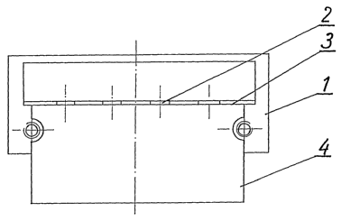
Representative Drawing
A single figure which represents the drawing illustrating the invention.
Administrative Status

For a clearer understanding of the status of the application/patent presented on this page, the site Disclaimer , as well as the definitions for Patent , Administrative Status , Maintenance Fee  and Payment History  should be consulted.

Administrative Status

Title Date
Forecasted Issue Date Unavailable
(86) PCT Filing Date 2006-01-31
(87) PCT Publication Date 2006-08-10
(85) National Entry 2007-07-30
Examination Requested 2011-01-31
Dead Application 2016-02-02

Abandonment History

Abandonment Date Reason Reinstatement Date
2015-02-02 FAILURE TO PAY APPLICATION MAINTENANCE FEE
2015-05-27 R30(2) - Failure to Respond

Payment History

Fee Type Anniversary Year Due Date Amount Paid Paid Date
Application Fee $400.00 2007-07-30
Maintenance Fee - Application - New Act 2 2008-01-31 $100.00 2008-01-29
Registration of a document - section 124 $100.00 2008-08-20
Maintenance Fee - Application - New Act 3 2009-02-02 $100.00 2009-01-14
Maintenance Fee - Application - New Act 4 2010-02-01 $100.00 2010-01-26
Maintenance Fee - Application - New Act 5 2011-01-31 $200.00 2010-12-13
Request for Examination $800.00 2011-01-31
Maintenance Fee - Application - New Act 6 2012-01-31 $200.00 2012-01-09
Maintenance Fee - Application - New Act 7 2013-01-31 $200.00 2013-01-15
Maintenance Fee - Application - New Act 8 2014-01-31 $200.00 2014-01-22
Owners on Record

Note: Records showing the ownership history in alphabetical order.

Current Owners on Record
SKOFF SPOLKA Z O.O.
Past Owners on Record
SKIBA, KRZYSTOF
Past Owners that do not appear in the "Owners on Record" listing will appear in other documentation within the application.
Documents

To view selected files, please enter reCAPTCHA code :


To view images, click a link in the Document Description column. To download the documents, select one or more checkboxes in the first column and then click the "Download Selected in PDF format (Zip Archive)" or the "Download Selected as Single PDF" button.

List of published and non-published patent-specific documents on the CPD .

If you have any difficulty accessing content, you can call the Client Service Centre at 1-866-997-1936 or send them an e-mail at CIPO Client Service Centre.


Document
Description 
Date
(yyyy-mm-dd) 
Number of pages   Size of Image (KB) 
Abstract 2007-07-30 2 69
Claims 2007-07-30 1 26
Drawings 2007-07-30 2 29
Description 2007-07-30 3 123
Representative Drawing 2007-07-30 1 5
Cover Page 2007-10-17 1 39
Description 2013-08-14 3 113
Claims 2013-08-14 1 24
Description 2014-03-19 3 115
Claims 2014-03-19 2 44
Description 2014-10-27 6 300
Claims 2014-10-27 2 50
Drawings 2014-10-27 2 28
Correspondence 2011-02-10 1 69
PCT 2007-07-30 3 92
Assignment 2007-07-30 6 144
Correspondence 2007-10-15 1 26
Fees 2008-01-29 1 42
Correspondence 2008-03-27 4 76
Assignment 2008-08-20 2 64
Correspondence 2008-11-07 1 15
Fees 2009-01-14 1 54
Fees 2010-01-26 1 51
Correspondence 2010-08-10 1 46
Fees 2010-12-13 1 52
Prosecution-Amendment 2011-01-31 2 59
Fees 2012-01-09 1 53
Fees 2013-01-15 1 55
Prosecution-Amendment 2013-02-14 4 136
Prosecution-Amendment 2014-04-28 6 284
Prosecution-Amendment 2013-08-14 9 289
Prosecution-Amendment 2013-09-20 3 123
Fees 2014-01-22 1 53
Prosecution-Amendment 2014-03-19 8 237
Prosecution-Amendment 2014-10-27 32 1,394
Prosecution-Amendment 2014-11-27 15 795