Sélection de la langue

Search

Sommaire du brevet 2596418 

Énoncé de désistement de responsabilité concernant l'information provenant de tiers

Une partie des informations de ce site Web a été fournie par des sources externes. Le gouvernement du Canada n'assume aucune responsabilité concernant la précision, l'actualité ou la fiabilité des informations fournies par les sources externes. Les utilisateurs qui désirent employer cette information devraient consulter directement la source des informations. Le contenu fourni par les sources externes n'est pas assujetti aux exigences sur les langues officielles, la protection des renseignements personnels et l'accessibilité.

Disponibilité de l'Abrégé et des Revendications

L'apparition de différences dans le texte et l'image des Revendications et de l'Abrégé dépend du moment auquel le document est publié. Les textes des Revendications et de l'Abrégé sont affichés :

  • lorsque la demande peut être examinée par le public;
  • lorsque le brevet est émis (délivrance).
(12) Demande de brevet: (11) CA 2596418
(54) Titre français: AJUSTEMENT D'ECLAIREMENT
(54) Titre anglais: PLANAR-LIGHTING ASSEMBLY WITH UNIFORMLY LIGHT EMITTING FRONT SURFACE AND EDGES
Statut: Morte
Données bibliographiques
(51) Classification internationale des brevets (CIB):
  • G02B 6/00 (2006.01)
  • F21V 8/00 (2006.01)
(72) Inventeurs :
  • SKIBA, KRZYSTOF (Pologne)
(73) Titulaires :
  • SKOFF SPOLKA Z O.O. (Pologne)
(71) Demandeurs :
  • SKOFF SPOLKA Z O.O. (Pologne)
(74) Agent: ROBIC
(74) Co-agent:
(45) Délivré:
(86) Date de dépôt PCT: 2006-01-31
(87) Mise à la disponibilité du public: 2006-08-10
Requête d'examen: 2011-01-31
Licence disponible: S.O.
(25) Langue des documents déposés: Anglais

Traité de coopération en matière de brevets (PCT): Oui
(86) Numéro de la demande PCT: PCT/PL2006/000008
(87) Numéro de publication internationale PCT: WO2006/083188
(85) Entrée nationale: 2007-07-30

(30) Données de priorité de la demande:
Numéro de la demande Pays / territoire Date
P372550 Pologne 2005-02-02

Abrégés

Abrégé français

L'objet de l'invention est l'ajustement d'éclairement utilisant une source à base de diodes LED de lumière C, appliquée pour construire des cadres fonctionnels, des marches et des contremarches d'escalier, des étagères de mobilier, des connecteurs de courant d'éclairage par l'arrière et des chemins d'éclairement de circulation dans des bâtiments et des structures. L'ajustement d'éclairement est fourni par un système électrique et il comporte un boîtier (1) présentant un flanc ouvert, comportant une source lumineuse (2) placée à l'intérieur. Sur le côté de l'ouverture du boîtier (1), il y a un élément de fibre optique (4) sous la forme d'une plaque façonnée dont au moins deux bords (3) et (7) transmettent le flux lumineux, l'un se trouvant du côté de la source lumineuse (2), de manière similaire à la paroi avant (5) de l'élément de fibre optique (4), alors que la paroi arrière (6) de l'élément de fibre optique (4) est partiellement ou totalement matée ou couverte d'un matériau de réflexion de la lumière ou d'un matériau fluorescent.


Abrégé anglais


The object of the invention is the lighting fitting using LED-based source of
C light, applied for constructing functional frames, backlighting stair treads
and stair risers, furniture shelves, backlighting current connectors and
lighting traffic routes in buildings and structures. The lighting fitting is
supplied by an electrical system and it has a casing (1) with one side open
with a source of light (2) placed inside it. On the side of the casing (1)
opening, there is an optical fibre element (4) in the form of a shaped plate
whose at least two edges (3) and (7) transmit the luminous flux, with one on
the side of the light source (2), similarly as the front wall (5) of the
optical fibre element (4), while the back wall (6) of the optical fibre
element (4) is partly or wholly matted or covered with a light reflecting
material or fluorescent material.

Revendications

Note : Les revendications sont présentées dans la langue officielle dans laquelle elles ont été soumises.


4


Claims

1. The lighting fitting, supplied by an electrical system, characterised by
the
fact that it has a casing (1) with one side open with a source of light (2)
placed inside it and, on the side of the casing (1) opening, there is an
optical fibre element (4) in the form of a shaped plate, preferably with two
parallel surfaces forming the front wall (5) and the back wall (6), whose at
least two edges (3) and (7) transmit the luminous flux, with one on the side
of the light source (2), similarly as the front wall (5) of the optical fibre
element (4), while the back wall (6) of the optical fibre element (4) is
partly
or wholly matted or covered with a light reflecting material or fluorescent
material.


2. The lighting fitting, according to Claim 1, characterised by the fact that
the edge (7) of the optical fibre element (4) is perpendicular, diagonal,
semicircular or shape-ended in relation to the back wall (6) of the optical
fibre element (4).


Description

Note : Les descriptions sont présentées dans la langue officielle dans laquelle elles ont été soumises.


CA 02596418 2007-07-30
WO 2006/083188 PCT/PL2006/000008
LIGHTING FITTING

The object of the invention is the lighting fitting using LED-based source of
light, applied for constructing functional frames, backlighting stair treads
and stair
risers, furniture shelves, backlighting current connectors and lighting
traffic routes
in buildings and structures.

There is known a Polish patent application no. P-364017 for a lighting clip
fixed around an edge of a transparent or semi-transparent panel in a removable
or
permanent way and supplied by an electric power system. The clip is in the
form of
a section, with at least one open side, consisted of clamping arms connected
with a
connector and provided with at least one source of light from the inside. The
section is in the form of a self-supporting elastic shape, with at least one
open side,
built of clamping arms of different length, where one of the arms is diagonal
to the
external panel surface or the section is in the form of a self-supporting
elastic
shape, with at least one open side, built of clamping arms of equal length,
where
both arms are diagonal to the panel surface, or the section is in the form of
a
shape, open on one side, which consists of two clamping arms which are
parallel.


CA 02596418 2007-07-30
WO 2006/083188 PCT/PL2006/000008
2
There is known a Polish patent application no. P-371391 for a lighting fitting

used for backlighting, from inside surfaces, transparent or semi-transparent
materials in the form of glass or plastic panes, especially glass shelves in
shelf
units or glass table and desk tops. The lighting fitting is supplied by an
electric
power system and it has an internal ring on its both sides provided with
covers of
external diameter bigger than the external diameter of the ring, where there
is at
least one source of light, preferably in the form of LED elements, on the
external
side surface of the internal ring. Preferably, external surfaces of the covers
are
parallel and preferably they are in the form of cylindrical discs or
cylindrical discs
where covers and the internal ring are provided with a passage in their
central part
or one of the covers is in the form of a supporting unit or both covers are in
the
form of a supporting unit.

The lighting fitting, supplied by an electrical system, according to the
invention
is characterised by the fact that it has a casing with one side open with a
source of
light placed inside it and, on the side of the casing opening, there is an
optical fibre
element in the form of a shaped plate, preferably with two parallel surfaces
forming
the front and back wall, whose at least two edges transmit the luminous flux,
with
one on the side of the light source, similarly as the front wall of the
optical fibre
element, while the back wall of the optical fibre element is partly or wholly
matted or
covered with a light reflecting material or fluorescent material. The edge of
the
optical fibre element is perpendicular, diagonal, semicircular or shape-ended
in
relation to the back wall of the optical fibre element.


CA 02596418 2007-07-30
WO 2006/083188 PCT/PL2006/000008
3
The object of the invention has been presented as an example product in the

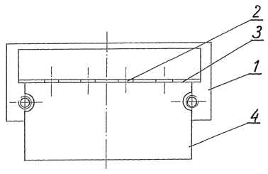
drawing, where Fig. 1 presents a front view of the lighting fitting, Fig. 2
presents a
cross section of the lighting fitting, Fig. 3 shows half-view of the lighting
fitting seen '
from the side of the optical fibre element and its half-section seen from the
side
with a source of light, Fig. 4 presents the lighting fitting seen from -its
fixing side,
Fig. 5 presents a side view of the shape of walls of the optical fibre element
with
parallel walls, Fig. 6 shows a side view of walls of the optical fibre element
with
diagonal walls; Fig. 7 presents a side view of the shape of the bottom
straight edge
of the optical fibre element, Fig. 8 presents a side view of the shape of the
bottom
diagonal edge of the optical fibre element, and Fig. 9 shows a side view of
the
shape of the bottom shaped edge of the optical fibre element.

As it has been presented in the drawing, the lighting fitting is supplied by
an
electrical system and it consists of an open casing 1, with a source of light
2 placed
inside it. A source of light is preferably in the form of LED elements which
are
situated along one edge 3 of the optical fibre element 4, pervious to the
source of
light, where that element is placed on the open side of the casing 1. The
optical
fibre element 4 is in the form of a shaped plate, preferably with two parallel
surfaces that form the front wall 5 and the back wall 6, whose at least two
edges 3
and 7 transmit the luminous flux, similarly as the front wall 5 of the optical
fibre
element 4, while the back wall 6 of the optical fibre element 4 is partiy of
wholly
matted or covered with a light reflecting material or fluorescent material.
The edge
7 of the optical fibre element 4 is perpendicular, diagonal, semicircular or
shape-
ended in relation to the back wall 6 of the optical fibre element 4.
Dessin représentatif
Une figure unique qui représente un dessin illustrant l'invention.
États administratifs

Pour une meilleure compréhension de l'état de la demande ou brevet qui figure sur cette page, la rubrique Mise en garde , et les descriptions de Brevet , États administratifs , Taxes périodiques et Historique des paiements devraient être consultées.

États administratifs

Titre Date
Date de délivrance prévu Non disponible
(86) Date de dépôt PCT 2006-01-31
(87) Date de publication PCT 2006-08-10
(85) Entrée nationale 2007-07-30
Requête d'examen 2011-01-31
Demande morte 2016-02-02

Historique d'abandonnement

Date d'abandonnement Raison Reinstatement Date
2015-02-02 Taxe périodique sur la demande impayée
2015-05-27 R30(2) - Absence de réponse

Historique des paiements

Type de taxes Anniversaire Échéance Montant payé Date payée
Le dépôt d'une demande de brevet 400,00 $ 2007-07-30
Taxe de maintien en état - Demande - nouvelle loi 2 2008-01-31 100,00 $ 2008-01-29
Enregistrement de documents 100,00 $ 2008-08-20
Taxe de maintien en état - Demande - nouvelle loi 3 2009-02-02 100,00 $ 2009-01-14
Taxe de maintien en état - Demande - nouvelle loi 4 2010-02-01 100,00 $ 2010-01-26
Taxe de maintien en état - Demande - nouvelle loi 5 2011-01-31 200,00 $ 2010-12-13
Requête d'examen 800,00 $ 2011-01-31
Taxe de maintien en état - Demande - nouvelle loi 6 2012-01-31 200,00 $ 2012-01-09
Taxe de maintien en état - Demande - nouvelle loi 7 2013-01-31 200,00 $ 2013-01-15
Taxe de maintien en état - Demande - nouvelle loi 8 2014-01-31 200,00 $ 2014-01-22
Titulaires au dossier

Les titulaires actuels et antérieures au dossier sont affichés en ordre alphabétique.

Titulaires actuels au dossier
SKOFF SPOLKA Z O.O.
Titulaires antérieures au dossier
SKIBA, KRZYSTOF
Les propriétaires antérieurs qui ne figurent pas dans la liste des « Propriétaires au dossier » apparaîtront dans d'autres documents au dossier.
Documents

Pour visionner les fichiers sélectionnés, entrer le code reCAPTCHA :


Pour visualiser une image, cliquer sur un lien dans la colonne description du document. Pour télécharger l'image (les images), cliquer l'une ou plusieurs cases à cocher dans la première colonne et ensuite cliquer sur le bouton "Télécharger sélection en format PDF (archive Zip)" ou le bouton "Télécharger sélection (en un fichier PDF fusionné)".

Liste des documents de brevet publiés et non publiés sur la BDBC .

Si vous avez des difficultés à accéder au contenu, veuillez communiquer avec le Centre de services à la clientèle au 1-866-997-1936, ou envoyer un courriel au Centre de service à la clientèle de l'OPIC.


Description du
Document 
Date
(yyyy-mm-dd) 
Nombre de pages   Taille de l'image (Ko) 
Abrégé 2007-07-30 2 69
Revendications 2007-07-30 1 26
Dessins 2007-07-30 2 29
Description 2007-07-30 3 123
Dessins représentatifs 2007-07-30 1 5
Page couverture 2007-10-17 1 39
Description 2013-08-14 3 113
Revendications 2013-08-14 1 24
Description 2014-03-19 3 115
Revendications 2014-03-19 2 44
Description 2014-10-27 6 300
Revendications 2014-10-27 2 50
Dessins 2014-10-27 2 28
Correspondance 2011-02-10 1 69
PCT 2007-07-30 3 92
Cession 2007-07-30 6 144
Correspondance 2007-10-15 1 26
Taxes 2008-01-29 1 42
Correspondance 2008-03-27 4 76
Cession 2008-08-20 2 64
Correspondance 2008-11-07 1 15
Taxes 2009-01-14 1 54
Taxes 2010-01-26 1 51
Correspondance 2010-08-10 1 46
Taxes 2010-12-13 1 52
Poursuite-Amendment 2011-01-31 2 59
Taxes 2012-01-09 1 53
Taxes 2013-01-15 1 55
Poursuite-Amendment 2013-02-14 4 136
Poursuite-Amendment 2014-04-28 6 284
Poursuite-Amendment 2013-08-14 9 289
Poursuite-Amendment 2013-09-20 3 123
Taxes 2014-01-22 1 53
Poursuite-Amendment 2014-03-19 8 237
Poursuite-Amendment 2014-10-27 32 1 394
Poursuite-Amendment 2014-11-27 15 795