Language selection

Search

Patent 2606540 Summary

Third-party information liability

Some of the information on this Web page has been provided by external sources. The Government of Canada is not responsible for the accuracy, reliability or currency of the information supplied by external sources. Users wishing to rely upon this information should consult directly with the source of the information. Content provided by external sources is not subject to official languages, privacy and accessibility requirements.

Claims and Abstract availability

Any discrepancies in the text and image of the Claims and Abstract are due to differing posting times. Text of the Claims and Abstract are posted:

  • At the time the application is open to public inspection;
  • At the time of issue of the patent (grant).
(12) Patent: (11) CA 2606540
(54) English Title: CHECK VALVE, ESPECIALLY FOR MEDICAL USE
(54) French Title: CLAPET ANTIRETOUR, NOTAMMENT A USAGE MEDICAL
Status: Granted
Bibliographic Data
(51) International Patent Classification (IPC):
  • A61M 39/24 (2006.01)
  • F16K 15/14 (2006.01)
(72) Inventors :
  • MIJERS, JAN WILLEM MARINUS (Netherlands (Kingdom of the))
  • HOGAN, BRENDAN (Ireland)
(73) Owners :
  • ILLINOIS TOOL WORKS INC. (United States of America)
(71) Applicants :
  • FILTERTEK B.V. (Ireland)
(74) Agent: CASSAN MACLEAN IP AGENCY INC.
(74) Associate agent:
(45) Issued: 2010-11-09
(86) PCT Filing Date: 2005-06-15
(87) Open to Public Inspection: 2005-12-29
Examination requested: 2007-10-30
Availability of licence: N/A
(25) Language of filing: English

Patent Cooperation Treaty (PCT): Yes
(86) PCT Filing Number: PCT/EP2005/006425
(87) International Publication Number: WO2005/123176
(85) National Entry: 2007-10-30

(30) Application Priority Data:
Application No. Country/Territory Date
20 2004 009 521.1 Germany 2004-06-17

Abstracts

English Abstract


The invention relates to a non-return valve, particularly for medial
applications, comprising a first tube connection housing (2), a second tube
connection housing (4) and a diaphragm disk (6), which is made of flexible
material, is placed between both tube connection housings, and which, in the
existence of an excess pressure inside an entry passage in the first tube
connection housing, can be lifted off from a valve seat (12) annularly
surrounding an inlet space connected to the entry passage (8). In the
existence of an excess pressure inside an outlet passage (24), the diaphragm
disk can be securely pressed against the valve seat in the shortest of times,
and is provided with an annular bead (14) on its outer peripheral area. This
annular bead is accommodated inside opposing annular grooves of the hose
connection housing. The diaphragm disk is provided with openings (20) radially
outside the valve seat that are connected to an outlet space. A formation
(28), which lies on the side of the diaphragm disk (6) facing the outlet space
(22) and which holds or prestresses the diaphragm disk (6) in the direction of
the inlet space (10), is provided on the wall (26) of the second tube
connection housing (4) located opposite the diaphragm disk (6). Said formation
(28) is placed inside the boundary given by the valve seat (12).


French Abstract

L'invention concerne un clapet antiretour, notamment à usage médical, comprenant un premier boîtier de raccordement de flexible et un second boîtier de raccordement de flexible, ainsi qu'un disque membranaire disposé entre les deux boîtiers de raccordement de flexible et consistant en un matériau flexible, qui peut être soulevé, en cas de surpression dans un passage d'accès, dans le premier boîtier de raccordement de flexible, par un siège de soupape annulaire, entourant l'espace d'entrée relié au passage d'accès et qui, en cas de surpression dans un passage de sortie, peut être comprimé de manière fiable et dans des temps minimaux, sur le siège de soupape. Le disque membranaire comporte au niveau de sa zone périphérique extérieure, un bourrelet annulaire qui est logé dans des rainures annulaires opposées des boîtiers de raccordement de flexible. Le disque membranaire est muni d'ouvertures, dans le sens radial en dehors du siège de soupape, lesdites ouvertures étant reliées à un espace de sortie. Sur la paroi (26) opposée au disque membranaire (6), du second boîtier de raccordement de flexible (4), il est prévu une formation (28) située sur la face du disque membranaire (6) tournée vers l'espace de sortie (22). Ladite formation maintient ou contraint le disque membranaire (6) en direction de l'espace d'entrée (10). Ladite formation (28) est disposée à l'intérieur de la limite définie par le siège de soupape (12).

Claims

Note: Claims are shown in the official language in which they were submitted.


What is claimed is:


1. A check valve for liquid applications comprising:
a first hose connector housing defining an entry passage extending into an
entry space at least partially defined by an annular valve seat;
a second hose connector housing coupled with the first hose connector
housing, the second hose connector housing defining an exit passage, an outer
rim,
a plurality of supporting surfaces spaced circumferentially about the exit
passage the
supporting surfaces defining recesses therebetween, and at least one groove
fluidly
connecting at least one recess with the exit passage, the second hose
connector
housing defining a series of discontinuous protrusions spaced
circumferentially about
the exit passage and extending generally toward the entry passage; and
a generally flexible membrane disk clamped between the first and second
hose connector housings such that the membrane disk engages the protrusions
and
selectively engages the valve seat, the membrane disk defining at least one
opening
located radially outwardly from the valve seat, where the membrane disk is
configured
to be movable between a seated position, where the entry space and the exit
passage
are fluidly sealed from each other by the membrane disk, and an unseated
position,
where the entry space and the exit passage are fluidly connected via the at
least one
opening;
wherein the valve seat is located radially outwardly from the protrusions such

that the protrusions about the exit passage circumferentially support the
membrane
disk toward the entry space and pretensions the membrane disk against the
valve seat
such that an unseating pressure required to move the membrane disk from the
seated
position to the unseated position is at least partially determined by the
radial distances
between the valve seat and the protrusions, and wherein the supporting
surfaces each
define a first radial portion extending substantially along the radial
distance between
the exit passage and the outer rim and a second radial portion connected to
the first
radial portion adjacent the exit passage and extending across a portion of the
radial
distance between the exit passage and the outer rim, thereby defining a second
recess


8


between the first radial portion and second radial portion fluidly connected
to the
recess between supporting surfaces, wherein the membrane disk opening overlies
a
recess between the first and second radial portions such that the membrane
disk at
the unseated position under high differential pressures engages the first and
second
radial portions.


2. A check valve as in claim 1, wherein the protrusions are configured to
permit fluid flow from the opening in the membrane disk to the exit passage.


3. A check valve as in claim 2, wherein the protrusions are generally
circumferentially equally spaced.


4. A check valve as in claim 3, wherein the protrusions define a generally
crown-shaped formation.


5. A check valve as in claim 4, wherein the protrusions and the second
hose connector housing are a single, unitary component.


6. A check valve as in claim 1, wherein the coupled first and second hose
connector housings define an annular groove of greater diameter than the
annulus of
the valve seat, and the membrane disk includes an annular protrusion, wherein
the
disk annular protrusion is configured to be received in the annular groove
defined by
the coupled first and second hose connector housings.


7. A check valve for liquid applications comprising:
a first hose connector housing defining an entry passage extending into an
entry space at least partially defined by an annular valve seat;
a second hose connector housing coupled with the first hose connector
housing, the second hose connector housing defining an exit passage, an outer
rim,
a plurality of supporting surfaces circumferentially about the exit passage,
wherein


9


each supporting surface includes a projection located within the diameter of
the
annular valve seat and extending generally toward the entry passage and
further
includes a first radial portion extending substantially along the radial
distance between
the exit passage and the outer rim, the supporting surfaces defining recesses
therebetween, and at least one groove fluidly connecting at least one recess
with the
exit passage; and
a generally flexible membrane disk clamped between the first and second
hose connector housing such that the membrane disk engages the supporting
surface
projections to pretension the membrane disk against the valve seat and
selectively
engage the valve seat, the membrane disk defining at least one opening located

radially outwardly from the valve seat, where the membrane disk is configured
to be
movable between a seated position, where the entry space and the recess are
fluidly
sealed from each other, and an unseated position, where the entry space and
the
recess are fluidly connected via the at least one opening such as to fluidly
connect the
entry passage with the exit passage;
wherein the membrane disk is positioned such that at least one membrane
disk opening overlies at least one recess in the second hose connector housing
and
the membrane disk at the unseated position under high differential pressures
engages
the first radial portions and fluidly connects the entry space with the exit
passage via
the at least one membrane disk opening, the recess, and the groove in the
second
hose connector housing, and wherein the supporting surfaces each further
define a
second radial portion connected to the first radial portion adjacent the exit
passage and
extending across a portion of the radial distance between the exit passage and
the
outer rim, thereby defining a second recess between the first radial portion
and second
radial portion fluidly connected to the recess between supporting surfaces,
wherein the
membrane disk opening overlies the recess between the first and second radial
portions such that the membrane disk and the unseated position under high
differential
pressures engages the first and second radial portions of the supporting
surface
projections to thereby fluidly connect the entry space with the exit passage
via the
membrane disk opening, the recess between the first and second radial
portions, the


10


recess between supporting surfaces and the groove in the second hose connector

housing.


8. A check valve as in claim 7, wherein the second hose connector housing
defines a plurality of recesses respectively positioned between adjacent
supporting
surfaces and a plurality of grooves each fluidly connecting one of the
recesses with the
exit passage.


9. A check valve as in claim 8, wherein the supporting surfaces each extend
generally radially to the outer rim of the second hose connector housing.


10. A check valve as in claim 9, wherein the supporting surfaces define a
broadening width along a direction toward an outer rim of the second hose
connector
housing.


11. A check valve as in claim 8, wherein each of the grooves is positioned
between adjacent supporting surfaces.


12. A check valve as in claim 8, wherein the membrane disk defines a
plurality of openings located radially outwardly from the valve seat and
wherein each
of the openings is generally kidney-shaped.


13. A check valve as in claim 12, wherein the second hose connector
housing defines six supporting surfaces and the membrane disk defines eight
openings.


14. A check valve as in claim 7, wherein the supporting surface projections
are positioned on the inner end of the supporting surface and adjacent to the
exit
passage, and positioned within a radius of the valve seat.


11


15. A check valve as in claim 7, wherein the supporting surfaces each have
at least a portion that define a generally concave surface.


16. A check valve as in claim 7, wherein the coupled first and second hose
connector housings define an annular groove of greater diameter than the
annulus of
the valve seat, and the membrane disk includes an annular protrusion, wherein
the
disk annular protrusion is configured to be received in the annular groove
defined by
the coupled first and second hose connector housings.


17. A check valve as in claim 7, wherein the coupled first and second hose
connector housings define an annular groove of greater diameter than the
annulus of
the valve seat, and the membrane disk includes an annular protrusion, wherein
the
disk annular protrusion is configured to be received in the annular groove
defined by
the coupled first and second hose connector housings.


18. A check valve as in claim 7, wherein the coupled first and second hose
connector housings define an annular groove of greater diameter than the
annulus of
the valve seat, and the membrane disk includes an annular protrusion, wherein
the
disk annular protrusion is configured to be received in the annular groove
defined by
the coupled first and second hose connector housings.


19. A check valve as in claim 18, wherein the supporting surfaces each have
at least a portion that define a generally concave surface.


12

Description

Note: Descriptions are shown in the official language in which they were submitted.


CA 02606540 2007-10-30

WO 2005/123176 PCT/EP2005/006425
Check Valve, especially for Medical Use.


The invention relates to a check valve, especially for medical
use, having a first hose connector housing and a second hose
connector housing and a membrane disk of flexible material po-
sitioned between the two hose connector housings which with an
overpressure in an entry passage in the first hose connector
housing can be lifted from an annular valve seat surrounding
an entry space connected with the entry passage and which with
an overpressure in an exit passage safely and in minimal time
can be pressed onto the valve seat, wherein the membrane disk
at the outer circumference thereof is provided with an annular
protrusion which is received within annular grooves oppositely
provided in the hose connector housings, wherein the membrane
disk radially exterior of the valve seat is provided with
openings which are connected to an exit space.

Such a check valve is known from the European patent 0 612 537
according to a prior proposal of the applicant.

In the medical technique, such check valves are used for the
lines of infusion systems, syringes, diagnosis equipment, in-
travenous hose lines and in connection with syringe pumps.
Such check valves have to have closing times of few fractions
of seconds and have to close safely to avoid any reflux of
possibly contaminated fluids. Since such check valves in the
medical technique merely are used as a one-way article simul-
taneously the production, on the one hand, has to be extremely
economical and, on the other hand, statistically very accu-
rate. Additionally, there are stringent legal provisions and
1


CA 02606540 2007-10-30

WO 2005/123176 PCT/EP2005/006425
tests to ensure a continuous and uniform safety in function.
In Germany, this for example is tested in detail by the TUV
before after achieving positive results, a release for the
medical application is achieved. These demands have been met
in connection with the above-mentioned check valves according
to a prior proposal of the applicant since in this known con-
struction the annular grooves receiving the annular protrusion
at the circumferential area of the membrane are designed such
that during the assembly the two hose connector housings are
creating radially directed tension forces in the membrane disk
such that thereby an adjustment of the tension forces in the
membrane can be achieved ensuring an extremely fast and safe
action of the check valve.

The practical use of this known check valve however has shown
that it is desirable to enable the provision of valves having
higher opening pressures in a simple manner. For example in
connection with the use of syringe pumps it has to be ensured
that said pump not simply can run empty due to the difference
in height between the patient and syringe pump since the valve
could already open because of the geodetic height. Since such
valves however usually are assembled from injection moulded
parts, the production of valves having different opening pres-
sures lead to substantial costs of the moulds.
Followingly, it is the task to be solved by the present inven-
tion to improve valves of the above-identified kind in such a
way that by simple means different opening pressures can be
provided.
In a valve of the above-identified kind this task basically is
solved according to the invention by the features that on the
wall of the second hose connector housing opposite to the men-
brane disk there is provided a formation engaging the side of
2


CA 02606540 2007-10-30

WO 2005/123176 PCT/EP2005/006425
the membrane disk facing the exit space which is holding or
pretensioning, respectively, the membrane disk in the direc-
tion of the entry space and that the formation is positioned
within the limits defined by the valve seat.
It is obvious that by the support of the membrane disk within
the valve seat provided by the formation or by the magnitude
of the opposite pretension created by the formation within the
membrane disk a simple possibility is provided to manufacture
valves of different opening pressures by either modifying the
radius within which such a formation is positioned within the
limits of the valve seat or modifying the height of the forma-
tion and followingly the magnitude of the opposite pretension.
This with low mould costs can simply be achieved by merely
modifying one half of the mould used for the production of the
second hose connector housing.

In a preferred embodiment according to the invention, the for-
mation is made pervious to media, i.e. that the formation is
scarcely impeding the flow through the opened valve.

An especially preferred embodiment according to the invention
can be created by the features that the formation is formed by
a number of projections which are surrounding the entry open-
ing of the exit passage from the exit space in the shape of a
crown.

Further, it is preferred that the formations are monolithic
with the second hose connector housing.
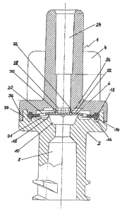
In the following, the invention is more detailly described
with reference to an exemplary embodiment shown in the draw-
ing. The drawing shows a cross-sectional view of the check
3


CA 02606540 2007-10-30

WO 2005/123176 PCT/EP2005/006425
valve according to the invention in one possible embodiment
and in the final assembled state.

The check valve 1 shown in the drawing is especially suitable
for medical use and is for example suitable for opening pres-
sures between 0,14 and 0,42 bar while check valves of the
above-identified kind according to a prior proposal of the ap-
plicant are designed for pressure differences between 0,1 to
0,002 bar.
The check valve 1 is consisting of a first hose connector
housing 2 and a second hose connector housing 4 which for ex-
ample are produced by injection moulding from plastics and a
membrane disk 6 clamped between these housings. The membrane
disk 6 is consisting of a flexible material, e.g. silicon.

The first hose connector housing 2 is having a first entry
passage 8 leading to an entry space 10. The entry space 10 is
surrounded by an annular valve seat 12 against which the mem-
brane disk 6 is pretensioned.

The membrane 6 in the area within the valve seat 12 is unitary
such that substantial tension forces can be transmitted ra-
dially from the interior to the exterior and vice versa. At
the outer circumferential area the membrane 6 is provided with
an annular protrusion 14 which for example is injection
moulded to the membrane disk 6 in case the membrane disk, too,
is made by injection moulding of the silicon. In the first
hose connector housing 2 in the front face thereof there is
provided an annular groove 16, wherein an annular groove 18 of
the second hose connector housing in the assembled state is
oppositely positioned. During the assembly of the first hose
connector housing with the second hose connector housing the
annular protrusion 14 is received within the two oppositely
4


CA 02606540 2007-10-30

WO 2005/123176 PCT/EP2005/006425
positioned annular grooves 16 and 18 of the two hose connector
housings 2 and 4 and simultaneously the membrane disk 6 is
pretensioned against the valve seat 12.

As further can be learnt from the drawing, the membrane disk 6
radially exterior of the valve seat 12 is provided with open-
ings 20 positioned on a radius which are connecting an annular
space 21 in the first hose connector housing 2 radially exte-
rior of the valve seat 12 with an exit space 22 of the second
hose connector housing 4, the latter being connected with an
exit passage 24 of the second hose connector housing 4.

The wall 26 of the second hose connector housing 4 is posi-
tioned opposite to the membrane disk 6 and is limiting the
exit space 22 in the upward direction. On the wall 26 there
are provided projecting formations generally designated with
28 which are pervious to media. The formations 28 are support-
ing the membrane disk 6 or are pretensioning the membrane disk
6 in the direction of the entry space 10, respectively. As
shown, the formations 28 are positioned within the limits de-
fined by the valve seat 12.

In the exemplary embodiment shown, the formation 28 is formed
by a number of projections 30. The projections 30 in the shape
of a crown are surrounding the entry opening 32 of the exit
passage starting from the exit space. As shown, the projec-
tions 30 by injection moulding are formed monolithically with
the second hose connector housing 4. It is obvious that by the
height of the projections 30 the oppositely directed preten-
sion exerted on the membrane disk 6 can be modified which ob-
viously is leading to a modification of the opening pressure
of the check valve 1. As an alternative it is possible, too,
to modify the distance between the valve seat 12 and the pro-
jections 30 in a radial direction, wherein thereby the lever
5


CA 02606540 2007-10-30

WO 2005/123176 PCT/EP2005/006425
between these parts is changed in its size. Hereby, too, a
modification of the opening pressure of the check valve 1 is
possible.

For the assembly the two hose connector housings 2 and 4 by
means of an inner annular projection 34 on the first hose con-
nector housing 2 and by means of an exterior annular projec-
tion 36 on the second hose connector housing 4 which are in-
terengaging can be connected. After providing this connection,
the final assembly for example can be done by ultrasonic weld-
ing.

All features and advantages of the invention which can be
learnt from the specification, the claims and the drawing in-
cluding constructive details and positions in space can be
substantial for the invention individually as well as in cb-
liberate combination.

REFERENCE NUMERALS
1 = check valve
2 = first hose connector housing
4 = second hose connector housing
6 = membrane disk
8 = first entry passage
10 = entry space
12 = annular valve seat
14 = annular protrusion
16 = annular groove
18 = annular groove
20 = openings
22 = exit space
24 = exit passage
26 = wall

6


CA 02606540 2009-12-09
28 = formation
30 = projections
32 = entry opening
34 = inner annular projection
36 = exterior annular projection

20
30
'7

Representative Drawing
A single figure which represents the drawing illustrating the invention.
Administrative Status

For a clearer understanding of the status of the application/patent presented on this page, the site Disclaimer , as well as the definitions for Patent , Administrative Status , Maintenance Fee  and Payment History  should be consulted.

Administrative Status

Title Date
Forecasted Issue Date 2010-11-09
(86) PCT Filing Date 2005-06-15
(87) PCT Publication Date 2005-12-29
(85) National Entry 2007-10-30
Examination Requested 2007-10-30
(45) Issued 2010-11-09

Abandonment History

There is no abandonment history.

Maintenance Fee

Last Payment of $473.65 was received on 2023-06-09


 Upcoming maintenance fee amounts

Description Date Amount
Next Payment if small entity fee 2024-06-17 $253.00
Next Payment if standard fee 2024-06-17 $624.00

Note : If the full payment has not been received on or before the date indicated, a further fee may be required which may be one of the following

  • the reinstatement fee;
  • the late payment fee; or
  • additional fee to reverse deemed expiry.

Patent fees are adjusted on the 1st of January every year. The amounts above are the current amounts if received by December 31 of the current year.
Please refer to the CIPO Patent Fees web page to see all current fee amounts.

Payment History

Fee Type Anniversary Year Due Date Amount Paid Paid Date
Request for Examination $800.00 2007-10-30
Reinstatement of rights $200.00 2007-10-30
Application Fee $400.00 2007-10-30
Maintenance Fee - Application - New Act 2 2007-06-15 $100.00 2007-10-30
Maintenance Fee - Application - New Act 3 2008-06-16 $100.00 2008-05-30
Registration of a document - section 124 $100.00 2009-03-11
Maintenance Fee - Application - New Act 4 2009-06-15 $100.00 2009-06-01
Maintenance Fee - Application - New Act 5 2010-06-15 $200.00 2010-05-27
Final Fee $300.00 2010-08-31
Maintenance Fee - Patent - New Act 6 2011-06-15 $200.00 2011-05-17
Registration of a document - section 124 $100.00 2011-12-29
Maintenance Fee - Patent - New Act 7 2012-06-15 $200.00 2012-05-17
Maintenance Fee - Patent - New Act 8 2013-06-17 $200.00 2013-05-17
Maintenance Fee - Patent - New Act 9 2014-06-16 $200.00 2014-06-09
Maintenance Fee - Patent - New Act 10 2015-06-15 $250.00 2015-06-08
Maintenance Fee - Patent - New Act 11 2016-06-15 $250.00 2016-06-13
Maintenance Fee - Patent - New Act 12 2017-06-15 $250.00 2017-06-12
Maintenance Fee - Patent - New Act 13 2018-06-15 $250.00 2018-06-11
Maintenance Fee - Patent - New Act 14 2019-06-17 $250.00 2019-06-07
Maintenance Fee - Patent - New Act 15 2020-06-15 $450.00 2020-06-05
Maintenance Fee - Patent - New Act 16 2021-06-15 $459.00 2021-06-11
Maintenance Fee - Patent - New Act 17 2022-06-15 $458.08 2022-06-10
Maintenance Fee - Patent - New Act 18 2023-06-15 $473.65 2023-06-09
Owners on Record

Note: Records showing the ownership history in alphabetical order.

Current Owners on Record
ILLINOIS TOOL WORKS INC.
Past Owners on Record
FILTERTEK B.V.
HOGAN, BRENDAN
MIJERS, JAN WILLEM MARINUS
Past Owners that do not appear in the "Owners on Record" listing will appear in other documentation within the application.
Documents

To view selected files, please enter reCAPTCHA code :


To view images, click a link in the Document Description column. To download the documents, select one or more checkboxes in the first column and then click the "Download Selected in PDF format (Zip Archive)" or the "Download Selected as Single PDF" button.

List of published and non-published patent-specific documents on the CPD .

If you have any difficulty accessing content, you can call the Client Service Centre at 1-866-997-1936 or send them an e-mail at CIPO Client Service Centre.


Document
Description 
Date
(yyyy-mm-dd) 
Number of pages   Size of Image (KB) 
Abstract 2007-10-30 2 121
Claims 2007-10-30 2 41
Drawings 2007-10-30 1 47
Description 2007-10-30 7 189
Representative Drawing 2008-01-24 1 15
Cover Page 2008-01-25 1 57
Claims 2009-12-09 5 214
Description 2009-12-09 7 188
Cover Page 2010-10-22 2 64
Prosecution-Amendment 2009-12-09 9 306
Office Letter 2018-02-05 1 30
PCT 2007-10-30 3 90
Assignment 2007-10-30 4 246
Correspondence 2008-01-23 1 25
PCT 2007-10-31 7 205
Prosecution-Amendment 2009-03-11 1 42
Assignment 2009-03-11 6 224
Correspondence 2009-03-11 3 81
Correspondence 2009-05-04 1 17
Prosecution-Amendment 2009-07-03 2 58
Correspondence 2010-03-02 1 30
Correspondence 2010-08-31 1 54
Correspondence 2012-01-19 1 14
Assignment 2011-12-29 3 99