Language selection

Search

Patent 2629630 Summary

Third-party information liability

Some of the information on this Web page has been provided by external sources. The Government of Canada is not responsible for the accuracy, reliability or currency of the information supplied by external sources. Users wishing to rely upon this information should consult directly with the source of the information. Content provided by external sources is not subject to official languages, privacy and accessibility requirements.

Claims and Abstract availability

Any discrepancies in the text and image of the Claims and Abstract are due to differing posting times. Text of the Claims and Abstract are posted:

  • At the time the application is open to public inspection;
  • At the time of issue of the patent (grant).
(12) Patent: (11) CA 2629630
(54) English Title: ELECTRIC MOTOR WITH A LOW NUMBER OF REVOLUTIONS, IN PARTICULAR TO DRIVE LIFTING DEVICES
(54) French Title: MOTEUR ELECTRIQUE AVEC UN FAIBLE NOMBRE DE REVOLUTIONS, EN PARTICULIER POUR ENTRAINER DES DISPOSITIFS DE LEVAGE
Status: Deemed expired
Bibliographic Data
(51) International Patent Classification (IPC):
  • H02K 7/10 (2006.01)
  • B66B 11/04 (2006.01)
  • H02K 19/10 (2006.01)
(72) Inventors :
  • JEZEK, GIORGIO (Italy)
(73) Owners :
  • JEZEK, GIORGIO (Italy)
(71) Applicants :
  • JEZEK, GIORGIO (Italy)
(74) Agent: BERESKIN & PARR LLP/S.E.N.C.R.L.,S.R.L.
(74) Associate agent:
(45) Issued: 2011-07-26
(86) PCT Filing Date: 2007-03-19
(87) Open to Public Inspection: 2007-11-15
Examination requested: 2008-04-23
Availability of licence: N/A
(25) Language of filing: English

Patent Cooperation Treaty (PCT): Yes
(86) PCT Filing Number: PCT/IB2007/000669
(87) International Publication Number: WO2007/129150
(85) National Entry: 2008-04-21

(30) Application Priority Data:
Application No. Country/Territory Date
BZ2006A000015 Italy 2006-04-28
BZ2006A000018 Italy 2006-05-09
TN2006A000007 Italy 2006-05-10

Abstracts

English Abstract


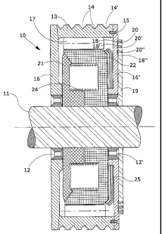
An electric motor (10) with a low number of revolutions comprises a rotor (17)
powered by three-phase alternating voltage, a series of magnets (21, 22) and a
coil forming a stator (24), in which the rotor (17) and the stator (24) have
the same number of magnetic poles. The stator (24) is powered with direct
voltage, and the frequency of the rotor voltage (17) is varied to obtain a
predetermined number of rpm of the motor and to vary the acceleration and
deceleration conditions of the motor. A thrust bearing opposes the effort of
the falling brake disc.


French Abstract

La présente invention concerne un moteur électrique (10) avec un faible nombre de révolutions qui comprend un rotor (17) alimenté par tension alternative triphasée, une série d'aimants (21, 22) et une bobine qui forme un stator (24), dans lequel le rotor (17) et le stator (24) possèdent le même nombre de pôles magnétiques. Le stator (24) est alimenté avec une tension directe, et la fréquence de la tension de rotor (17) est variée pour obtenir un nombre prédéterminé de tr/min du moteur et pour varier les conditions d'accélération et de décélération du moteur. Un palier de butée s'oppose à l'effort du disque de frein qui tombe.

Claims

Note: Claims are shown in the official language in which they were submitted.


7

Claims


1. An electric motor (10) for low numbers of revolutions comprising a rotor
(17),
three-phase alternating voltage power supply means (18, 19. 20) of the rotor,
a stator (24)
formed of a series of magnets (21, 22) made from ferrous material and a coil,
a brake
system (25), in which the rotor (17) and the stator (24) have the same number
of
magnetic poles, said rotor (17), the stator (24) and the magnets (21, 22) are
enclosed in a
pulley casing (13) which rotates around a fixed shaft (11), said rotor (17)
being fixed to
the pulley casing (13), the coil of the stator (24) is powered by direct
voltage, and that the
frequency of the rotor voltage (17) is variable, and the magnets (21, 22)
forming the
stator (24) are fixed to the shaft (11) and designed to accommodate the coil
of the stator
(24); characterized in that
.cndot. said pulley case (13) comprises a pulley and a pair of diamagnetic
side plates
(16, 16') rigidly fixed to the pulley, and
.cndot. said brake system (25) is enclosed in said pulley casing (13) and
comprises an
electromagnetic brake (25) consisting of a pair of metal discs and disc-
pushing springs, one of said discs being integral with one of said diamagnetic

plates (16') and the other of said discs being integral with the magnet (22)
which produce the poles of the stator (24), and said disc-pushing springs
being
located in appropriate slots cut in said magnet (22) integral with said disc.


2. An electric motor according to claim 1, wherein the two brake discs have a
concave shape consisting of a central discoid section having at its periphery
a section in
the shape of a truncated cone.


3. An electric motor according to any one of claims 1-2, wherein said
diamagnetic side
plates (16, 16') work in conjunction with a pair of roller bearings (12, 12')
cooperating
with said shaft (11).


8

4. An electric motor (10) according to any one of claims 1-3, further
comprising a
fixed protective guard (19) fitted with a series of brushes (20, 20', 20")
connected to
respective rings (18, 18', 18") rotating with the pulley casing, and
electrically connected
to the three-phase rotor windings.


5. An electric motor according to any one of claims 1-4, wherein the pulley
casing
(13) presents a series of peripheral slots (14) designed to accommodate drive
cables.


6. An electric motor according to any one of claims 1-5, further comprising an

internal mechanical brake unit.


7. An electric motor according to any one of claims 1-6, wherein the rotor and
stator
are integral with a motion transmission organ.


8. An electric motor according to claim 7, wherein the motion transmission
organ
consists of a toothed wheel or a friction wheel.

Description

Note: Descriptions are shown in the official language in which they were submitted.


CA 02629630 2008-04-21
WO 2007/129150 PCT/IB2007/000669
1
Electric motor with a low number of revolutions, in
particular to drive lifting devices.

* * * * *
Technical field
This invention refers to an electric motor with a
low number of revolutions.
In particular, this invention refers to an electric
motor with a low number of revolutions which can be
advantageously used for applications requiring torque.
By way of example, the electric motor according to
the invention can be used to drive lifting devices, such
as lifts.
Background art
Electric motors used in applications with a heavy
torque requirement, for example electric motors for
lifts, are generally positioned inside relatively small
spaces, which is a source of problems as the motors are
usually fairly large due to the presence, in addition to
the motor itself, of a reduction unit and obviously the
pulley around which the cables that raise and lower the
lift cabin are wound.
The reduction units used in these applications
often have electromechnical characteristics that are
fairly inconstant over time, leading to functioning
irregularities that cause a considerable reduction in
the performance of the motor.


CA 02629630 2008-04-21
WO 2007/129150 PCT/IB2007/000669

2
Description of the invention
This invention proposes to provide a solution to
the background art problems, thanks to a new design of
motor which is small and is not equipped with a
reduction unit.
In particular, in the lifts sector, this invention
proposes to provide an electric motor with a low number
of revolutions (for example a motor with approximately
50 rpm corresponding to a lifting speed of around 1
m/sec) thanks to which the components necessary for the
movement and the braking of the machine can be directly
contained inside the drive pulley.
This is achieved by means of an electric motor with
the features described in the main claim. The dependent
claims describe particularly advantageous embodiments of
the electric motor according to the invention.
The most typical configuration of the electric
motor according to the invention consists of a rotor
(with a high number of magnetic poles) powered by three-
phase alternating voltage, and of a stator with the same
number of magnetic poles as the rotor, created by a coil
powered by direct voltage.
According to a particularly advantageous embodiment
of the invention, the direct voltage consists of a
single-phase rectified and thus pulsating alternating
voltage. This direct voltage makes it possible to obtain
excellent results in terms of motor performance.
Description of the drawings
Other features and advantages of the invention will
become clear on reading the description of some


CA 02629630 2008-04-21
WO 2007/129150 PCT/IB2007/000669

3
embodiments of the invention, given as non-binding
examples, with the help of the accompanying drawing
which shows a cross-section of an electric motor
according to the invention.
Description of some embodiments of the invention
In the figure, the reference number 10 indicates
overall an electric motor with a low number of
revolutions used to drive lifting devices according to
the invention.
The motor 10 is supported by a fixed metal shaft 11
by means of a pair of bearings 12, 12' (either roller or
ball bearings) and is enclosed in the casing 13 of a
pulley, the outer surface of which is equipped with a
series of slots 14, 14' ... designed to accommodate
cables (not shown in the figure) for driving a lifting
device, for example a lift. The casing 13 is rigidly
fixed by means of screws 15 to a pair of diamagnetic
side plates 16, 16' which work in conjunction with the
said roller bearings 12, 12'.
The actual electric motor is housed inside the
space formed by the diamagnetic plates 16, 16' and the
pulley casing 13.
In particular, integral with the inner surf ace of
the pulley 13 is a rotor pack 17 fitted with a series of
slots (not shown in the figure) designed to accommodate
a three-phase winding powered by alternating voltage.
This three-phase winding is connected to three
respective conductor rings 18, 18', 18" inserted in
appropriate slots cut in the side plate 16'. In
addition, a protective guard 19 consisting of two


CA 02629630 2008-04-21
WO 2007/129150 PCT/IB2007/000669

4
portions joined together and fixed to the shaft 11
supports three respective brushes 20, 20', 20" in
contact with the said conductor rings 18, 18', 18".
Respective magnets 21, 22 are positioned next to
each other and fixed to the shaft 11. These magnets 21,
22 define a space which houses a stator-powered coil 24
powered by direct voltage in order to create the
magnetic polarities of the stator.
Finally, the motor 10 comprises an electromagnetic
brake 25 consisting of a pair of metal discs, one of
which is integral with the side plate 16' and the other
with the magnet 22, and of disc-pushing springs
contained in appropriate slots cut in the magnet 22.
Such a motor is particularly suited for application
as a machine without a reduction unit in the lifts
sector, since the drive pulley can contain all the
equipment necessary both to move and to brake the
machine.
According to the invention, the respective power
supplies of the stator coil 24 (advantageously direct
voltage obtained by rectifying single-phase alternating
voltage) and of the rotor windings 17 (three-phase
alternating voltage) are governed by means of an
appropriate control device, until the required number of
revolutions is reached, which depends on the number of
poles of the motor and on the frequency of the three-
phase power supply.
The control device that can be used for these
applications is the variable frequency type, for example
the ac-dc-ac or dc-ac type.
According to the invention, the stator coil 24 is


CA 02629630 2008-04-21
WO 2007/129150 PCT/IB2007/000669

powered by direct voltage. In this embodiment, the motor
comprises a high number of magnetic poles, both stator
and rotor having the same number, and in the stator the
poles are the clawed type as in automobile alternators.
5 Some features of the synchronous motor in terms of
performance are lost in this case, achieving however an
acceleration torque that makes it possible to obtain the
required number of revolutions from the rotor by merely
varying the frequency of the three-phase power supply of
the rotor itself.
In order to avoid flow leakage between the driving
shaft and the coil, the side plates 16, 16' are made
from diamagnetic material.
As far as the steady state speed and the braking
and acceleration phases are concerned, the stator 24 is
constantly powered by direct voltage, while the rotor 17
has a variable frequency achieved by means of a
frequency converter external to the rotor. In this case,
during the acceleration and deceleration phases the
frequency of the three-phase voltage of the rotor 17 is
adjusted by frequency converters (ac-dc-ac or dc-ac)
which provide the frequencies, currents and thus the
torques required.
The invention is described above with reference to
a preferred embodiment, in which the main shaft is
fixed, the stator is integral with the shaft and the
rotor turns around the shaft and the stator.
Embodiments of this invention are nevertheless
foreseen in which the conformation of the motor is
inverted, and the main shaft rotates, while the motor
casing integral with the three-phase windings is fixed.


CA 02629630 2008-04-21
WO 2007/129150 PCT/IB2007/000669

6
In this case, the main shaft is equipped with a
pair of conductor rings connected to appropriate cables
inserted in slots in the shaft and connected to windings
of the coil and of the rotating magnets.
A pair of brushes is then connected to the rings
for transmission of the current, while the mechanical
drive organs, in particular the lifting organs, are
connected to the main shaft.

Representative Drawing
A single figure which represents the drawing illustrating the invention.
Administrative Status

For a clearer understanding of the status of the application/patent presented on this page, the site Disclaimer , as well as the definitions for Patent , Administrative Status , Maintenance Fee  and Payment History  should be consulted.

Administrative Status

Title Date
Forecasted Issue Date 2011-07-26
(86) PCT Filing Date 2007-03-19
(87) PCT Publication Date 2007-11-15
(85) National Entry 2008-04-21
Examination Requested 2008-04-23
(45) Issued 2011-07-26
Deemed Expired 2015-03-19

Abandonment History

There is no abandonment history.

Payment History

Fee Type Anniversary Year Due Date Amount Paid Paid Date
Application Fee $200.00 2008-04-21
Request for Examination $400.00 2008-04-23
Maintenance Fee - Application - New Act 2 2009-03-19 $100.00 2009-02-20
Maintenance Fee - Application - New Act 3 2010-03-19 $100.00 2010-02-08
Maintenance Fee - Application - New Act 4 2011-03-21 $100.00 2011-02-10
Final Fee $300.00 2011-05-04
Maintenance Fee - Patent - New Act 5 2012-03-19 $200.00 2012-02-23
Maintenance Fee - Patent - New Act 6 2013-03-19 $200.00 2013-02-21
Owners on Record

Note: Records showing the ownership history in alphabetical order.

Current Owners on Record
JEZEK, GIORGIO
Past Owners on Record
None
Past Owners that do not appear in the "Owners on Record" listing will appear in other documentation within the application.
Documents

To view selected files, please enter reCAPTCHA code :


To view images, click a link in the Document Description column. To download the documents, select one or more checkboxes in the first column and then click the "Download Selected in PDF format (Zip Archive)" or the "Download Selected as Single PDF" button.

List of published and non-published patent-specific documents on the CPD .

If you have any difficulty accessing content, you can call the Client Service Centre at 1-866-997-1936 or send them an e-mail at CIPO Client Service Centre.


Document
Description 
Date
(yyyy-mm-dd) 
Number of pages   Size of Image (KB) 
Abstract 2008-04-21 1 78
Claims 2008-04-21 3 80
Drawings 2008-04-21 1 47
Description 2008-04-21 6 207
Representative Drawing 2011-06-23 1 24
Cover Page 2011-06-23 1 56
Representative Drawing 2008-07-30 1 23
Cover Page 2008-07-30 2 58
Claims 2009-04-29 2 58
Claims 2010-05-31 2 61
PCT 2008-04-21 3 98
Assignment 2008-04-21 5 140
Prosecution-Amendment 2008-04-23 3 74
Correspondence 2009-02-19 2 55
Correspondence 2009-03-19 1 16
Correspondence 2009-03-19 1 20
Correspondence 2009-02-20 2 75
Fees 2009-02-20 2 75
Prosecution-Amendment 2009-04-29 3 89
Prosecution-Amendment 2010-01-05 2 72
Prosecution-Amendment 2010-05-31 7 249
Correspondence 2011-05-04 1 41
Fees 2012-02-23 1 61
Fees 2013-02-21 1 58