Sélection de la langue

Search

Sommaire du brevet 2629630 

Énoncé de désistement de responsabilité concernant l'information provenant de tiers

Une partie des informations de ce site Web a été fournie par des sources externes. Le gouvernement du Canada n'assume aucune responsabilité concernant la précision, l'actualité ou la fiabilité des informations fournies par les sources externes. Les utilisateurs qui désirent employer cette information devraient consulter directement la source des informations. Le contenu fourni par les sources externes n'est pas assujetti aux exigences sur les langues officielles, la protection des renseignements personnels et l'accessibilité.

Disponibilité de l'Abrégé et des Revendications

L'apparition de différences dans le texte et l'image des Revendications et de l'Abrégé dépend du moment auquel le document est publié. Les textes des Revendications et de l'Abrégé sont affichés :

  • lorsque la demande peut être examinée par le public;
  • lorsque le brevet est émis (délivrance).
(12) Brevet: (11) CA 2629630
(54) Titre français: MOTEUR ELECTRIQUE AVEC UN FAIBLE NOMBRE DE REVOLUTIONS, EN PARTICULIER POUR ENTRAINER DES DISPOSITIFS DE LEVAGE
(54) Titre anglais: ELECTRIC MOTOR WITH A LOW NUMBER OF REVOLUTIONS, IN PARTICULAR TO DRIVE LIFTING DEVICES
Statut: Réputé périmé
Données bibliographiques
(51) Classification internationale des brevets (CIB):
  • H02K 7/10 (2006.01)
  • B66B 11/04 (2006.01)
  • H02K 19/10 (2006.01)
(72) Inventeurs :
  • JEZEK, GIORGIO (Italie)
(73) Titulaires :
  • JEZEK, GIORGIO (Italie)
(71) Demandeurs :
  • JEZEK, GIORGIO (Italie)
(74) Agent: BERESKIN & PARR LLP/S.E.N.C.R.L.,S.R.L.
(74) Co-agent:
(45) Délivré: 2011-07-26
(86) Date de dépôt PCT: 2007-03-19
(87) Mise à la disponibilité du public: 2007-11-15
Requête d'examen: 2008-04-23
Licence disponible: S.O.
(25) Langue des documents déposés: Anglais

Traité de coopération en matière de brevets (PCT): Oui
(86) Numéro de la demande PCT: PCT/IB2007/000669
(87) Numéro de publication internationale PCT: WO2007/129150
(85) Entrée nationale: 2008-04-21

(30) Données de priorité de la demande:
Numéro de la demande Pays / territoire Date
BZ2006A000015 Italie 2006-04-28
BZ2006A000018 Italie 2006-05-09
TN2006A000007 Italie 2006-05-10

Abrégés

Abrégé français

La présente invention concerne un moteur électrique (10) avec un faible nombre de révolutions qui comprend un rotor (17) alimenté par tension alternative triphasée, une série d'aimants (21, 22) et une bobine qui forme un stator (24), dans lequel le rotor (17) et le stator (24) possèdent le même nombre de pôles magnétiques. Le stator (24) est alimenté avec une tension directe, et la fréquence de la tension de rotor (17) est variée pour obtenir un nombre prédéterminé de tr/min du moteur et pour varier les conditions d'accélération et de décélération du moteur. Un palier de butée s'oppose à l'effort du disque de frein qui tombe.


Abrégé anglais


An electric motor (10) with a low number of revolutions comprises a rotor (17)
powered by three-phase alternating voltage, a series of magnets (21, 22) and a
coil forming a stator (24), in which the rotor (17) and the stator (24) have
the same number of magnetic poles. The stator (24) is powered with direct
voltage, and the frequency of the rotor voltage (17) is varied to obtain a
predetermined number of rpm of the motor and to vary the acceleration and
deceleration conditions of the motor. A thrust bearing opposes the effort of
the falling brake disc.

Revendications

Note : Les revendications sont présentées dans la langue officielle dans laquelle elles ont été soumises.


7

Claims


1. An electric motor (10) for low numbers of revolutions comprising a rotor
(17),
three-phase alternating voltage power supply means (18, 19. 20) of the rotor,
a stator (24)
formed of a series of magnets (21, 22) made from ferrous material and a coil,
a brake
system (25), in which the rotor (17) and the stator (24) have the same number
of
magnetic poles, said rotor (17), the stator (24) and the magnets (21, 22) are
enclosed in a
pulley casing (13) which rotates around a fixed shaft (11), said rotor (17)
being fixed to
the pulley casing (13), the coil of the stator (24) is powered by direct
voltage, and that the
frequency of the rotor voltage (17) is variable, and the magnets (21, 22)
forming the
stator (24) are fixed to the shaft (11) and designed to accommodate the coil
of the stator
(24); characterized in that
.cndot. said pulley case (13) comprises a pulley and a pair of diamagnetic
side plates
(16, 16') rigidly fixed to the pulley, and
.cndot. said brake system (25) is enclosed in said pulley casing (13) and
comprises an
electromagnetic brake (25) consisting of a pair of metal discs and disc-
pushing springs, one of said discs being integral with one of said diamagnetic

plates (16') and the other of said discs being integral with the magnet (22)
which produce the poles of the stator (24), and said disc-pushing springs
being
located in appropriate slots cut in said magnet (22) integral with said disc.


2. An electric motor according to claim 1, wherein the two brake discs have a
concave shape consisting of a central discoid section having at its periphery
a section in
the shape of a truncated cone.


3. An electric motor according to any one of claims 1-2, wherein said
diamagnetic side
plates (16, 16') work in conjunction with a pair of roller bearings (12, 12')
cooperating
with said shaft (11).


8

4. An electric motor (10) according to any one of claims 1-3, further
comprising a
fixed protective guard (19) fitted with a series of brushes (20, 20', 20")
connected to
respective rings (18, 18', 18") rotating with the pulley casing, and
electrically connected
to the three-phase rotor windings.


5. An electric motor according to any one of claims 1-4, wherein the pulley
casing
(13) presents a series of peripheral slots (14) designed to accommodate drive
cables.


6. An electric motor according to any one of claims 1-5, further comprising an

internal mechanical brake unit.


7. An electric motor according to any one of claims 1-6, wherein the rotor and
stator
are integral with a motion transmission organ.


8. An electric motor according to claim 7, wherein the motion transmission
organ
consists of a toothed wheel or a friction wheel.

Description

Note : Les descriptions sont présentées dans la langue officielle dans laquelle elles ont été soumises.


CA 02629630 2008-04-21
WO 2007/129150 PCT/IB2007/000669
1
Electric motor with a low number of revolutions, in
particular to drive lifting devices.

* * * * *
Technical field
This invention refers to an electric motor with a
low number of revolutions.
In particular, this invention refers to an electric
motor with a low number of revolutions which can be
advantageously used for applications requiring torque.
By way of example, the electric motor according to
the invention can be used to drive lifting devices, such
as lifts.
Background art
Electric motors used in applications with a heavy
torque requirement, for example electric motors for
lifts, are generally positioned inside relatively small
spaces, which is a source of problems as the motors are
usually fairly large due to the presence, in addition to
the motor itself, of a reduction unit and obviously the
pulley around which the cables that raise and lower the
lift cabin are wound.
The reduction units used in these applications
often have electromechnical characteristics that are
fairly inconstant over time, leading to functioning
irregularities that cause a considerable reduction in
the performance of the motor.


CA 02629630 2008-04-21
WO 2007/129150 PCT/IB2007/000669

2
Description of the invention
This invention proposes to provide a solution to
the background art problems, thanks to a new design of
motor which is small and is not equipped with a
reduction unit.
In particular, in the lifts sector, this invention
proposes to provide an electric motor with a low number
of revolutions (for example a motor with approximately
50 rpm corresponding to a lifting speed of around 1
m/sec) thanks to which the components necessary for the
movement and the braking of the machine can be directly
contained inside the drive pulley.
This is achieved by means of an electric motor with
the features described in the main claim. The dependent
claims describe particularly advantageous embodiments of
the electric motor according to the invention.
The most typical configuration of the electric
motor according to the invention consists of a rotor
(with a high number of magnetic poles) powered by three-
phase alternating voltage, and of a stator with the same
number of magnetic poles as the rotor, created by a coil
powered by direct voltage.
According to a particularly advantageous embodiment
of the invention, the direct voltage consists of a
single-phase rectified and thus pulsating alternating
voltage. This direct voltage makes it possible to obtain
excellent results in terms of motor performance.
Description of the drawings
Other features and advantages of the invention will
become clear on reading the description of some


CA 02629630 2008-04-21
WO 2007/129150 PCT/IB2007/000669

3
embodiments of the invention, given as non-binding
examples, with the help of the accompanying drawing
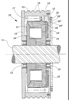
which shows a cross-section of an electric motor
according to the invention.
Description of some embodiments of the invention
In the figure, the reference number 10 indicates
overall an electric motor with a low number of
revolutions used to drive lifting devices according to
the invention.
The motor 10 is supported by a fixed metal shaft 11
by means of a pair of bearings 12, 12' (either roller or
ball bearings) and is enclosed in the casing 13 of a
pulley, the outer surface of which is equipped with a
series of slots 14, 14' ... designed to accommodate
cables (not shown in the figure) for driving a lifting
device, for example a lift. The casing 13 is rigidly
fixed by means of screws 15 to a pair of diamagnetic
side plates 16, 16' which work in conjunction with the
said roller bearings 12, 12'.
The actual electric motor is housed inside the
space formed by the diamagnetic plates 16, 16' and the
pulley casing 13.
In particular, integral with the inner surf ace of
the pulley 13 is a rotor pack 17 fitted with a series of
slots (not shown in the figure) designed to accommodate
a three-phase winding powered by alternating voltage.
This three-phase winding is connected to three
respective conductor rings 18, 18', 18" inserted in
appropriate slots cut in the side plate 16'. In
addition, a protective guard 19 consisting of two


CA 02629630 2008-04-21
WO 2007/129150 PCT/IB2007/000669

4
portions joined together and fixed to the shaft 11
supports three respective brushes 20, 20', 20" in
contact with the said conductor rings 18, 18', 18".
Respective magnets 21, 22 are positioned next to
each other and fixed to the shaft 11. These magnets 21,
22 define a space which houses a stator-powered coil 24
powered by direct voltage in order to create the
magnetic polarities of the stator.
Finally, the motor 10 comprises an electromagnetic
brake 25 consisting of a pair of metal discs, one of
which is integral with the side plate 16' and the other
with the magnet 22, and of disc-pushing springs
contained in appropriate slots cut in the magnet 22.
Such a motor is particularly suited for application
as a machine without a reduction unit in the lifts
sector, since the drive pulley can contain all the
equipment necessary both to move and to brake the
machine.
According to the invention, the respective power
supplies of the stator coil 24 (advantageously direct
voltage obtained by rectifying single-phase alternating
voltage) and of the rotor windings 17 (three-phase
alternating voltage) are governed by means of an
appropriate control device, until the required number of
revolutions is reached, which depends on the number of
poles of the motor and on the frequency of the three-
phase power supply.
The control device that can be used for these
applications is the variable frequency type, for example
the ac-dc-ac or dc-ac type.
According to the invention, the stator coil 24 is


CA 02629630 2008-04-21
WO 2007/129150 PCT/IB2007/000669

powered by direct voltage. In this embodiment, the motor
comprises a high number of magnetic poles, both stator
and rotor having the same number, and in the stator the
poles are the clawed type as in automobile alternators.
5 Some features of the synchronous motor in terms of
performance are lost in this case, achieving however an
acceleration torque that makes it possible to obtain the
required number of revolutions from the rotor by merely
varying the frequency of the three-phase power supply of
the rotor itself.
In order to avoid flow leakage between the driving
shaft and the coil, the side plates 16, 16' are made
from diamagnetic material.
As far as the steady state speed and the braking
and acceleration phases are concerned, the stator 24 is
constantly powered by direct voltage, while the rotor 17
has a variable frequency achieved by means of a
frequency converter external to the rotor. In this case,
during the acceleration and deceleration phases the
frequency of the three-phase voltage of the rotor 17 is
adjusted by frequency converters (ac-dc-ac or dc-ac)
which provide the frequencies, currents and thus the
torques required.
The invention is described above with reference to
a preferred embodiment, in which the main shaft is
fixed, the stator is integral with the shaft and the
rotor turns around the shaft and the stator.
Embodiments of this invention are nevertheless
foreseen in which the conformation of the motor is
inverted, and the main shaft rotates, while the motor
casing integral with the three-phase windings is fixed.


CA 02629630 2008-04-21
WO 2007/129150 PCT/IB2007/000669

6
In this case, the main shaft is equipped with a
pair of conductor rings connected to appropriate cables
inserted in slots in the shaft and connected to windings
of the coil and of the rotating magnets.
A pair of brushes is then connected to the rings
for transmission of the current, while the mechanical
drive organs, in particular the lifting organs, are
connected to the main shaft.

Dessin représentatif
Une figure unique qui représente un dessin illustrant l'invention.
États administratifs

Pour une meilleure compréhension de l'état de la demande ou brevet qui figure sur cette page, la rubrique Mise en garde , et les descriptions de Brevet , États administratifs , Taxes périodiques et Historique des paiements devraient être consultées.

États administratifs

Titre Date
Date de délivrance prévu 2011-07-26
(86) Date de dépôt PCT 2007-03-19
(87) Date de publication PCT 2007-11-15
(85) Entrée nationale 2008-04-21
Requête d'examen 2008-04-23
(45) Délivré 2011-07-26
Réputé périmé 2015-03-19

Historique d'abandonnement

Il n'y a pas d'historique d'abandonnement

Historique des paiements

Type de taxes Anniversaire Échéance Montant payé Date payée
Le dépôt d'une demande de brevet 200,00 $ 2008-04-21
Requête d'examen 400,00 $ 2008-04-23
Taxe de maintien en état - Demande - nouvelle loi 2 2009-03-19 100,00 $ 2009-02-20
Taxe de maintien en état - Demande - nouvelle loi 3 2010-03-19 100,00 $ 2010-02-08
Taxe de maintien en état - Demande - nouvelle loi 4 2011-03-21 100,00 $ 2011-02-10
Taxe finale 300,00 $ 2011-05-04
Taxe de maintien en état - brevet - nouvelle loi 5 2012-03-19 200,00 $ 2012-02-23
Taxe de maintien en état - brevet - nouvelle loi 6 2013-03-19 200,00 $ 2013-02-21
Titulaires au dossier

Les titulaires actuels et antérieures au dossier sont affichés en ordre alphabétique.

Titulaires actuels au dossier
JEZEK, GIORGIO
Titulaires antérieures au dossier
S.O.
Les propriétaires antérieurs qui ne figurent pas dans la liste des « Propriétaires au dossier » apparaîtront dans d'autres documents au dossier.
Documents

Pour visionner les fichiers sélectionnés, entrer le code reCAPTCHA :


Pour visualiser une image, cliquer sur un lien dans la colonne description du document. Pour télécharger l'image (les images), cliquer l'une ou plusieurs cases à cocher dans la première colonne et ensuite cliquer sur le bouton "Télécharger sélection en format PDF (archive Zip)" ou le bouton "Télécharger sélection (en un fichier PDF fusionné)".

Liste des documents de brevet publiés et non publiés sur la BDBC .

Si vous avez des difficultés à accéder au contenu, veuillez communiquer avec le Centre de services à la clientèle au 1-866-997-1936, ou envoyer un courriel au Centre de service à la clientèle de l'OPIC.


Description du
Document 
Date
(yyyy-mm-dd) 
Nombre de pages   Taille de l'image (Ko) 
Abrégé 2008-04-21 1 78
Revendications 2008-04-21 3 80
Dessins 2008-04-21 1 47
Description 2008-04-21 6 207
Dessins représentatifs 2011-06-23 1 24
Page couverture 2011-06-23 1 56
Dessins représentatifs 2008-07-30 1 23
Page couverture 2008-07-30 2 58
Revendications 2009-04-29 2 58
Revendications 2010-05-31 2 61
PCT 2008-04-21 3 98
Cession 2008-04-21 5 140
Poursuite-Amendment 2008-04-23 3 74
Correspondance 2009-02-19 2 55
Correspondance 2009-03-19 1 16
Correspondance 2009-03-19 1 20
Correspondance 2009-02-20 2 75
Taxes 2009-02-20 2 75
Poursuite-Amendment 2009-04-29 3 89
Poursuite-Amendment 2010-01-05 2 72
Poursuite-Amendment 2010-05-31 7 249
Correspondance 2011-05-04 1 41
Taxes 2012-02-23 1 61
Taxes 2013-02-21 1 58