Language selection

Search

Patent 2640537 Summary

Third-party information liability

Some of the information on this Web page has been provided by external sources. The Government of Canada is not responsible for the accuracy, reliability or currency of the information supplied by external sources. Users wishing to rely upon this information should consult directly with the source of the information. Content provided by external sources is not subject to official languages, privacy and accessibility requirements.

Claims and Abstract availability

Any discrepancies in the text and image of the Claims and Abstract are due to differing posting times. Text of the Claims and Abstract are posted:

  • At the time the application is open to public inspection;
  • At the time of issue of the patent (grant).
(12) Patent: (11) CA 2640537
(54) English Title: RAIL FASTENING DEVICE
(54) French Title: ACCESSOIRE DE POSE ET DE DEPOSE D'UN DISPOSITIF DE FIXATION DE RAIL
Status: Deemed expired
Bibliographic Data
(51) International Patent Classification (IPC):
  • E01B 29/28 (2006.01)
  • E01B 29/00 (2006.01)
  • E01B 29/24 (2006.01)
(72) Inventors :
  • KUMPFMUELLER, NICOLE (Germany)
  • MAUER, HARALD (Germany)
  • MROSOWSKI, DIETER (Germany)
  • WESTERHOFF, KARSTEN (Germany)
  • RINSDORF, ANDREAS (Germany)
(73) Owners :
  • DB NETZ AG (Germany)
(71) Applicants :
  • DB NETZ AG (Germany)
(74) Agent: RIDOUT & MAYBEE LLP
(74) Associate agent:
(45) Issued: 2012-04-03
(22) Filed Date: 2008-10-07
(41) Open to Public Inspection: 2009-05-09
Examination requested: 2008-10-07
Availability of licence: N/A
(25) Language of filing: English

Patent Cooperation Treaty (PCT): No

(30) Application Priority Data:
Application No. Country/Territory Date
10 2007 053 901.2 Germany 2007-11-09

Abstracts

English Abstract

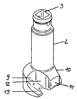
The invention describes a device for the assembly and disassembly of a fastening device, more preferably of a rail fastening device on a support body, wherein the device is designed as screw adapter and the screw adapter is to be placed on the rail fastening device. The invention is based on developing a device for the assembly and disassembly of a rail fastening device which sits on the fastening device with an accurate fit and largely guarantees automated screwing in and screwing out of the fastening device in existing engagement stages. According to the invention this is achieved in that the screw adapter comprising an engagement pin at its stem, in the contact surface of its main body possesses a centrally arranged recess to accommodate the head of a fastening element, wherein the main body on both sides next to this recess comprises two mounting pockets designed trough-shaped as well as a stop.


French Abstract

La présente invention décrit un dispositif de montage et de démontage d'un dispositif de fixation, de préférence un dispositif de fixation de rail sur un corps de soutien, où le dispositif est conçu comme un adaptateur de vis qui doit être placé sur le dispositif de fixation de rail. L'invention se fonde sur la création d'un dispositif de montage et de démontage d'un dispositif de fixation de rail qui repose sur le dispositif de fixation avec un ajustement précis, et garantit largement un serrage et un desserrage devis automatique lors des opérations d'engagement existantes. Selon l'invention, cet objectif est atteint du au fait que l'adaptateur de vis, qui comporte un axe d'engagement à sa tige, sur la surface de contact de son corps principal, est muni d'un évidement placé centralement afin de recevoir la tête d'un élément de fixation, où le corps principal des deux côtés proche dudit évidement comprend deux pochettes de montage qui sont prévues pour servir d'élément traversant et de butée.

Claims

Note: Claims are shown in the official language in which they were submitted.


Claims


1. A device for the assembly and disassembly of a fastening device wherein
the device is embodied as screw adapter having a stem and a main body
and the screw adapter is to be placed on the rail fastening device,
wherein the screw adapter which, on the stem comprises an engagement
pin, and in a contact surface of the main body possesses a centrally ar-
ranged recess to accommodate a head of a fastening element, wherein
the main body on both sides next to the recess comprises two trough-
shaped mounting pockets and a stop.


2. The device according to Claim 1, wherein the trough-shaped mounting
pockets on the main body each comprise a lateral guide.


3. The device according to Claim 1, wherein the trough-shaped mounting
pockets on the main body each comprise a flattened under-grip.

Description

Note: Descriptions are shown in the official language in which they were submitted.


CA 02640537 2011-04-12

RAIL FASTENING DEVICE
Description
The invention describes a device for the assembly and disassembly of a fasten-
ing device, more preferably a rail fastening device on a support body, wherein
the device is embodied as screw adapter and the screw adapter is to be placed
on the rail fastening device.
Various machines for rail fastening are known wherein the primary concern is
the screwing in or out of the bolts or the rail screws or the clamping devices
for
railway tracks (DE 25 50 819 Al, DE 601 03 475 T2, DE 37 20 381 Al).
Here, the screws used can be turned by means of simple hand-guided rotary
tools. No additional tool is generally required since the spring/clamp can be
manually moved once the screw has been loosened.

The disadvantage of all screwing devices known to date is that these can no
longer be used for new types of springs/clamps with a clip function for estab-
lishing turning-in from the preassembly into the operating position.

The invention is therefore based on developing a device for the assembly and
disassembly of a rail fastening device which sits on the fastening device with
an
accurate fit and substantially guarantees automated turning in and out of the
fastening device in existing engagement stages.

According to the invention this is achieved in that the screw adapter
comprising
an engagement pin at its stem possesses a centrally arranged recess to ac-
commodate the head of a fastening device in the contact surface of its main
body, wherein the main body on both sides next to this recess comprises two
mounting pockets embodied trough-shaped as well as a stop!


CA 02640537 2011-04-12

2
The mounting pockets on the main body embodied trough-shaped each com-
prise a lateral guide.

The mounting pockets in the main body embodied trough-shaped each com-
prise a flattened under-grip.

The device for the assembly and disassembly of rail fastening devices can be
employed with track constructions whose support bodies are embodied as both
known track sleepers irrespective of type as well as a concrete structure of
the
fixed road or as another structure.

Thus, according to the present invention, there is provided a device for the
as-
sembly and disassembly of a fastening device wherein the device is embodied
as a screw adapter having a stem and a main body. The screw adapter is to be
placed on the rail fastening device. The screw adapter on the stem comprises
an engagement pin, and in a contact surface of the main body, possesses a
centrally arranged recess to accommodate a head of a fastening element. The
main body on both sides next to the recess comprises two trough-shaped
mounting pockets and a stop.

Advantages of the invention

- The fastening device can be automatically turned from the preassembly
position in the operating or final assembly position and vice versa
- The exact starting of the screw adapter on the fastening device in the
preassembly position is made possible via positions which are defined in
the tool by means of engagement stages and which can be automatically
approached
- It is safeguarded that the final assembly position is achieved without
twisting/distortion of the fastening device
- The angular offset between the fastening device located on the inside of
the track and the fastening system located on the outside of the track
relative to the longitudinal axis of the device is automatically offset
through the appropriate engagement stages when approaching the next
engagement position in alternation track inside / track outside so that no
overloads can occur


CA 02640537 2011-04-12

3
During disassembly of a fastening device the screw adapter can be relo-
cated from the final assembly position to the preassembly position by
simply changing the direction of rotation
By forming an engagement pin at the stem of the screw adapter that can
be used for nearly all existing screwing devices it can be connected to all
hydraulic screwing devices
The screw adapter can be operated by one person without problems

The invention is explained in more detail in the following by means of an exem-

plary embodiment.

Here it shows:

- Figure 1 - the rail fastening system in top view
- Figure 2 - the rail fastening system in cross section
- Figure 3 - the corresponding screw adapter in lateral view
- Figure 4 - the screw adapter in the rearward view
- Figure 5 - the screw adapter in a three dimensional lateral view
- Figure 6 - the screw adapter in top view
- Figure 7 - the screw adapter with fastening system and element in
front view
- Figure 8 - the screw adapter with fastening system and element in lat-
eral view
- Figure 9 - the screw adapter with fastening system and element in a
three dimensional lateral view
- Figure 10 - the screw adapter with fastening system and element in top
view

The screw adapter 1 on its stem 2 comprises the engagement pin 3 of square
design to accommodate the screwing machine which is not shown (Figure 5).
The contact surface 4 of the main body 5 comprises a centrally arranged recess
6 for accommodating the head of the fastening element 7, which is sunk in the
support body embodied as sleeper 8 (Figure 1, 2).

Furthermore, the main body 5 on both sides comprises two mounting pockets 9;
10 embodied trough-shaped next to the recess 6 as well as centrally a stop 11
(Figure 3, 4, 6). The trough-shaped mounting pockets 9; 10 each additionally
comprise on the main body 5 the lateral guides 12; 13 and an under-grip 14; 15


CA 02640537 2011-04-12

4
of flattened design each for accommodating and fixing the spring loops of the
fastening device 16.

Figures 7 to 10 show the interaction of the screw adapter 1 with the fastening
device 16 and the fastening device 7.

Here, the screw adapter I as tool braces itself on the fastening device 7 cen-
trally in such a manner that the force (torque) introduced into the tool
during the
assembly or disassembly of the fastening device 15 leads to the turning-in of
the fastening device 15 onto the head of the fastening element 7 without the
possibility of deformation of said fastening element occurring.

The screw adapter 1 via the special shape of the trough-shaped mounting
pockets 9; 10 in conjunction with the two lateral guides 12, 13 and the
flattened
under-grips 14; 15 matingly engages the fastening device 16. Slipping-off of
the
screw adapter 1 cannot occur because of this engagement. The engagement
pin 3 is of square design to accommodate a screwing machine.

The screw adapter 1 automatically approaches the respective angles of rotation
(starting, turning in final assembly position, starting with rotational offset
on the
opposite side of the track) required and stops without overloading the
fastening
device 16 or the fastening element 7.

Representative Drawing
A single figure which represents the drawing illustrating the invention.
Administrative Status

For a clearer understanding of the status of the application/patent presented on this page, the site Disclaimer , as well as the definitions for Patent , Administrative Status , Maintenance Fee  and Payment History  should be consulted.

Administrative Status

Title Date
Forecasted Issue Date 2012-04-03
(22) Filed 2008-10-07
Examination Requested 2008-10-07
(41) Open to Public Inspection 2009-05-09
(45) Issued 2012-04-03
Deemed Expired 2016-10-07

Abandonment History

There is no abandonment history.

Payment History

Fee Type Anniversary Year Due Date Amount Paid Paid Date
Request for Examination $800.00 2008-10-07
Application Fee $400.00 2008-10-07
Maintenance Fee - Application - New Act 2 2010-10-07 $100.00 2010-06-28
Maintenance Fee - Application - New Act 3 2011-10-07 $100.00 2011-09-28
Final Fee $300.00 2012-01-18
Maintenance Fee - Patent - New Act 4 2012-10-09 $100.00 2012-09-25
Maintenance Fee - Patent - New Act 5 2013-10-07 $200.00 2013-09-26
Maintenance Fee - Patent - New Act 6 2014-10-07 $200.00 2014-09-25
Owners on Record

Note: Records showing the ownership history in alphabetical order.

Current Owners on Record
DB NETZ AG
Past Owners on Record
KUMPFMUELLER, NICOLE
MAUER, HARALD
MROSOWSKI, DIETER
RINSDORF, ANDREAS
WESTERHOFF, KARSTEN
Past Owners that do not appear in the "Owners on Record" listing will appear in other documentation within the application.
Documents

To view selected files, please enter reCAPTCHA code :


To view images, click a link in the Document Description column. To download the documents, select one or more checkboxes in the first column and then click the "Download Selected in PDF format (Zip Archive)" or the "Download Selected as Single PDF" button.

List of published and non-published patent-specific documents on the CPD .

If you have any difficulty accessing content, you can call the Client Service Centre at 1-866-997-1936 or send them an e-mail at CIPO Client Service Centre.


Document
Description 
Date
(yyyy-mm-dd) 
Number of pages   Size of Image (KB) 
Description 2011-04-12 4 150
Drawings 2011-04-12 3 49
Claims 2011-04-12 1 19
Abstract 2008-10-07 1 21
Description 2008-10-07 4 149
Claims 2008-10-07 1 23
Drawings 2008-10-07 3 61
Representative Drawing 2009-04-16 1 6
Cover Page 2009-05-06 1 44
Representative Drawing 2012-03-12 1 6
Cover Page 2012-03-12 2 44
Assignment 2008-10-07 5 134
Fees 2010-06-28 1 36
Prosecution-Amendment 2010-10-12 3 80
Fees 2011-09-28 1 163
Prosecution-Amendment 2011-04-12 11 292
Correspondence 2012-01-18 1 49