Sélection de la langue

Search

Sommaire du brevet 2640537 

Énoncé de désistement de responsabilité concernant l'information provenant de tiers

Une partie des informations de ce site Web a été fournie par des sources externes. Le gouvernement du Canada n'assume aucune responsabilité concernant la précision, l'actualité ou la fiabilité des informations fournies par les sources externes. Les utilisateurs qui désirent employer cette information devraient consulter directement la source des informations. Le contenu fourni par les sources externes n'est pas assujetti aux exigences sur les langues officielles, la protection des renseignements personnels et l'accessibilité.

Disponibilité de l'Abrégé et des Revendications

L'apparition de différences dans le texte et l'image des Revendications et de l'Abrégé dépend du moment auquel le document est publié. Les textes des Revendications et de l'Abrégé sont affichés :

  • lorsque la demande peut être examinée par le public;
  • lorsque le brevet est émis (délivrance).
(12) Brevet: (11) CA 2640537
(54) Titre français: ACCESSOIRE DE POSE ET DE DEPOSE D'UN DISPOSITIF DE FIXATION DE RAIL
(54) Titre anglais: RAIL FASTENING DEVICE
Statut: Réputé périmé
Données bibliographiques
(51) Classification internationale des brevets (CIB):
  • E01B 29/28 (2006.01)
  • E01B 29/00 (2006.01)
  • E01B 29/24 (2006.01)
(72) Inventeurs :
  • KUMPFMUELLER, NICOLE (Allemagne)
  • MAUER, HARALD (Allemagne)
  • MROSOWSKI, DIETER (Allemagne)
  • WESTERHOFF, KARSTEN (Allemagne)
  • RINSDORF, ANDREAS (Allemagne)
(73) Titulaires :
  • DB NETZ AG (Allemagne)
(71) Demandeurs :
  • DB NETZ AG (Allemagne)
(74) Agent: RIDOUT & MAYBEE LLP
(74) Co-agent:
(45) Délivré: 2012-04-03
(22) Date de dépôt: 2008-10-07
(41) Mise à la disponibilité du public: 2009-05-09
Requête d'examen: 2008-10-07
Licence disponible: S.O.
(25) Langue des documents déposés: Anglais

Traité de coopération en matière de brevets (PCT): Non

(30) Données de priorité de la demande:
Numéro de la demande Pays / territoire Date
10 2007 053 901.2 Allemagne 2007-11-09

Abrégés

Abrégé français

La présente invention décrit un dispositif de montage et de démontage d'un dispositif de fixation, de préférence un dispositif de fixation de rail sur un corps de soutien, où le dispositif est conçu comme un adaptateur de vis qui doit être placé sur le dispositif de fixation de rail. L'invention se fonde sur la création d'un dispositif de montage et de démontage d'un dispositif de fixation de rail qui repose sur le dispositif de fixation avec un ajustement précis, et garantit largement un serrage et un desserrage devis automatique lors des opérations d'engagement existantes. Selon l'invention, cet objectif est atteint du au fait que l'adaptateur de vis, qui comporte un axe d'engagement à sa tige, sur la surface de contact de son corps principal, est muni d'un évidement placé centralement afin de recevoir la tête d'un élément de fixation, où le corps principal des deux côtés proche dudit évidement comprend deux pochettes de montage qui sont prévues pour servir d'élément traversant et de butée.


Abrégé anglais

The invention describes a device for the assembly and disassembly of a fastening device, more preferably of a rail fastening device on a support body, wherein the device is designed as screw adapter and the screw adapter is to be placed on the rail fastening device. The invention is based on developing a device for the assembly and disassembly of a rail fastening device which sits on the fastening device with an accurate fit and largely guarantees automated screwing in and screwing out of the fastening device in existing engagement stages. According to the invention this is achieved in that the screw adapter comprising an engagement pin at its stem, in the contact surface of its main body possesses a centrally arranged recess to accommodate the head of a fastening element, wherein the main body on both sides next to this recess comprises two mounting pockets designed trough-shaped as well as a stop.

Revendications

Note : Les revendications sont présentées dans la langue officielle dans laquelle elles ont été soumises.


Claims


1. A device for the assembly and disassembly of a fastening device wherein
the device is embodied as screw adapter having a stem and a main body
and the screw adapter is to be placed on the rail fastening device,
wherein the screw adapter which, on the stem comprises an engagement
pin, and in a contact surface of the main body possesses a centrally ar-
ranged recess to accommodate a head of a fastening element, wherein
the main body on both sides next to the recess comprises two trough-
shaped mounting pockets and a stop.


2. The device according to Claim 1, wherein the trough-shaped mounting
pockets on the main body each comprise a lateral guide.


3. The device according to Claim 1, wherein the trough-shaped mounting
pockets on the main body each comprise a flattened under-grip.

Description

Note : Les descriptions sont présentées dans la langue officielle dans laquelle elles ont été soumises.


CA 02640537 2011-04-12

RAIL FASTENING DEVICE
Description
The invention describes a device for the assembly and disassembly of a fasten-
ing device, more preferably a rail fastening device on a support body, wherein
the device is embodied as screw adapter and the screw adapter is to be placed
on the rail fastening device.
Various machines for rail fastening are known wherein the primary concern is
the screwing in or out of the bolts or the rail screws or the clamping devices
for
railway tracks (DE 25 50 819 Al, DE 601 03 475 T2, DE 37 20 381 Al).
Here, the screws used can be turned by means of simple hand-guided rotary
tools. No additional tool is generally required since the spring/clamp can be
manually moved once the screw has been loosened.

The disadvantage of all screwing devices known to date is that these can no
longer be used for new types of springs/clamps with a clip function for estab-
lishing turning-in from the preassembly into the operating position.

The invention is therefore based on developing a device for the assembly and
disassembly of a rail fastening device which sits on the fastening device with
an
accurate fit and substantially guarantees automated turning in and out of the
fastening device in existing engagement stages.

According to the invention this is achieved in that the screw adapter
comprising
an engagement pin at its stem possesses a centrally arranged recess to ac-
commodate the head of a fastening device in the contact surface of its main
body, wherein the main body on both sides next to this recess comprises two
mounting pockets embodied trough-shaped as well as a stop!


CA 02640537 2011-04-12

2
The mounting pockets on the main body embodied trough-shaped each com-
prise a lateral guide.

The mounting pockets in the main body embodied trough-shaped each com-
prise a flattened under-grip.

The device for the assembly and disassembly of rail fastening devices can be
employed with track constructions whose support bodies are embodied as both
known track sleepers irrespective of type as well as a concrete structure of
the
fixed road or as another structure.

Thus, according to the present invention, there is provided a device for the
as-
sembly and disassembly of a fastening device wherein the device is embodied
as a screw adapter having a stem and a main body. The screw adapter is to be
placed on the rail fastening device. The screw adapter on the stem comprises
an engagement pin, and in a contact surface of the main body, possesses a
centrally arranged recess to accommodate a head of a fastening element. The
main body on both sides next to the recess comprises two trough-shaped
mounting pockets and a stop.

Advantages of the invention

- The fastening device can be automatically turned from the preassembly
position in the operating or final assembly position and vice versa
- The exact starting of the screw adapter on the fastening device in the
preassembly position is made possible via positions which are defined in
the tool by means of engagement stages and which can be automatically
approached
- It is safeguarded that the final assembly position is achieved without
twisting/distortion of the fastening device
- The angular offset between the fastening device located on the inside of
the track and the fastening system located on the outside of the track
relative to the longitudinal axis of the device is automatically offset
through the appropriate engagement stages when approaching the next
engagement position in alternation track inside / track outside so that no
overloads can occur


CA 02640537 2011-04-12

3
During disassembly of a fastening device the screw adapter can be relo-
cated from the final assembly position to the preassembly position by
simply changing the direction of rotation
By forming an engagement pin at the stem of the screw adapter that can
be used for nearly all existing screwing devices it can be connected to all
hydraulic screwing devices
The screw adapter can be operated by one person without problems

The invention is explained in more detail in the following by means of an exem-

plary embodiment.

Here it shows:

- Figure 1 - the rail fastening system in top view
- Figure 2 - the rail fastening system in cross section
- Figure 3 - the corresponding screw adapter in lateral view
- Figure 4 - the screw adapter in the rearward view
- Figure 5 - the screw adapter in a three dimensional lateral view
- Figure 6 - the screw adapter in top view
- Figure 7 - the screw adapter with fastening system and element in
front view
- Figure 8 - the screw adapter with fastening system and element in lat-
eral view
- Figure 9 - the screw adapter with fastening system and element in a
three dimensional lateral view
- Figure 10 - the screw adapter with fastening system and element in top
view

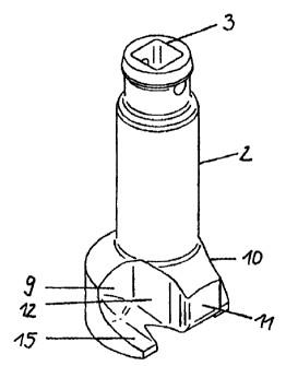
The screw adapter 1 on its stem 2 comprises the engagement pin 3 of square
design to accommodate the screwing machine which is not shown (Figure 5).
The contact surface 4 of the main body 5 comprises a centrally arranged recess
6 for accommodating the head of the fastening element 7, which is sunk in the
support body embodied as sleeper 8 (Figure 1, 2).

Furthermore, the main body 5 on both sides comprises two mounting pockets 9;
10 embodied trough-shaped next to the recess 6 as well as centrally a stop 11
(Figure 3, 4, 6). The trough-shaped mounting pockets 9; 10 each additionally
comprise on the main body 5 the lateral guides 12; 13 and an under-grip 14; 15


CA 02640537 2011-04-12

4
of flattened design each for accommodating and fixing the spring loops of the
fastening device 16.

Figures 7 to 10 show the interaction of the screw adapter 1 with the fastening
device 16 and the fastening device 7.

Here, the screw adapter I as tool braces itself on the fastening device 7 cen-
trally in such a manner that the force (torque) introduced into the tool
during the
assembly or disassembly of the fastening device 15 leads to the turning-in of
the fastening device 15 onto the head of the fastening element 7 without the
possibility of deformation of said fastening element occurring.

The screw adapter 1 via the special shape of the trough-shaped mounting
pockets 9; 10 in conjunction with the two lateral guides 12, 13 and the
flattened
under-grips 14; 15 matingly engages the fastening device 16. Slipping-off of
the
screw adapter 1 cannot occur because of this engagement. The engagement
pin 3 is of square design to accommodate a screwing machine.

The screw adapter 1 automatically approaches the respective angles of rotation
(starting, turning in final assembly position, starting with rotational offset
on the
opposite side of the track) required and stops without overloading the
fastening
device 16 or the fastening element 7.

Dessin représentatif
Une figure unique qui représente un dessin illustrant l'invention.
États administratifs

Pour une meilleure compréhension de l'état de la demande ou brevet qui figure sur cette page, la rubrique Mise en garde , et les descriptions de Brevet , États administratifs , Taxes périodiques et Historique des paiements devraient être consultées.

États administratifs

Titre Date
Date de délivrance prévu 2012-04-03
(22) Dépôt 2008-10-07
Requête d'examen 2008-10-07
(41) Mise à la disponibilité du public 2009-05-09
(45) Délivré 2012-04-03
Réputé périmé 2016-10-07

Historique d'abandonnement

Il n'y a pas d'historique d'abandonnement

Historique des paiements

Type de taxes Anniversaire Échéance Montant payé Date payée
Requête d'examen 800,00 $ 2008-10-07
Le dépôt d'une demande de brevet 400,00 $ 2008-10-07
Taxe de maintien en état - Demande - nouvelle loi 2 2010-10-07 100,00 $ 2010-06-28
Taxe de maintien en état - Demande - nouvelle loi 3 2011-10-07 100,00 $ 2011-09-28
Taxe finale 300,00 $ 2012-01-18
Taxe de maintien en état - brevet - nouvelle loi 4 2012-10-09 100,00 $ 2012-09-25
Taxe de maintien en état - brevet - nouvelle loi 5 2013-10-07 200,00 $ 2013-09-26
Taxe de maintien en état - brevet - nouvelle loi 6 2014-10-07 200,00 $ 2014-09-25
Titulaires au dossier

Les titulaires actuels et antérieures au dossier sont affichés en ordre alphabétique.

Titulaires actuels au dossier
DB NETZ AG
Titulaires antérieures au dossier
KUMPFMUELLER, NICOLE
MAUER, HARALD
MROSOWSKI, DIETER
RINSDORF, ANDREAS
WESTERHOFF, KARSTEN
Les propriétaires antérieurs qui ne figurent pas dans la liste des « Propriétaires au dossier » apparaîtront dans d'autres documents au dossier.
Documents

Pour visionner les fichiers sélectionnés, entrer le code reCAPTCHA :


Pour visualiser une image, cliquer sur un lien dans la colonne description du document. Pour télécharger l'image (les images), cliquer l'une ou plusieurs cases à cocher dans la première colonne et ensuite cliquer sur le bouton "Télécharger sélection en format PDF (archive Zip)" ou le bouton "Télécharger sélection (en un fichier PDF fusionné)".

Liste des documents de brevet publiés et non publiés sur la BDBC .

Si vous avez des difficultés à accéder au contenu, veuillez communiquer avec le Centre de services à la clientèle au 1-866-997-1936, ou envoyer un courriel au Centre de service à la clientèle de l'OPIC.


Description du
Document 
Date
(yyyy-mm-dd) 
Nombre de pages   Taille de l'image (Ko) 
Description 2011-04-12 4 150
Dessins 2011-04-12 3 49
Revendications 2011-04-12 1 19
Abrégé 2008-10-07 1 21
Description 2008-10-07 4 149
Revendications 2008-10-07 1 23
Dessins 2008-10-07 3 61
Dessins représentatifs 2009-04-16 1 6
Page couverture 2009-05-06 1 44
Dessins représentatifs 2012-03-12 1 6
Page couverture 2012-03-12 2 44
Cession 2008-10-07 5 134
Taxes 2010-06-28 1 36
Poursuite-Amendment 2010-10-12 3 80
Taxes 2011-09-28 1 163
Poursuite-Amendment 2011-04-12 11 292
Correspondance 2012-01-18 1 49