Language selection

Search

Patent 2661076 Summary

Third-party information liability

Some of the information on this Web page has been provided by external sources. The Government of Canada is not responsible for the accuracy, reliability or currency of the information supplied by external sources. Users wishing to rely upon this information should consult directly with the source of the information. Content provided by external sources is not subject to official languages, privacy and accessibility requirements.

Claims and Abstract availability

Any discrepancies in the text and image of the Claims and Abstract are due to differing posting times. Text of the Claims and Abstract are posted:

  • At the time the application is open to public inspection;
  • At the time of issue of the patent (grant).
(12) Patent: (11) CA 2661076
(54) English Title: MECHANICAL TAILGATE
(54) French Title: HAYON MECANIQUE
Status: Deemed expired
Bibliographic Data
(51) International Patent Classification (IPC):
  • B62D 33/03 (2006.01)
(72) Inventors :
  • RYDSTROEM, LARS (Sweden)
(73) Owners :
  • ATLAS COPCO ROCK DRILLS AB (Sweden)
(71) Applicants :
  • ATLAS COPCO ROCK DRILLS AB (Sweden)
(74) Agent: FETHERSTONHAUGH & CO.
(74) Associate agent:
(45) Issued: 2013-07-09
(86) PCT Filing Date: 2007-08-24
(87) Open to Public Inspection: 2008-03-13
Examination requested: 2011-06-09
Availability of licence: N/A
(25) Language of filing: English

Patent Cooperation Treaty (PCT): Yes
(86) PCT Filing Number: PCT/SE2007/000748
(87) International Publication Number: WO2008/030155
(85) National Entry: 2009-02-18

(30) Application Priority Data:
Application No. Country/Territory Date
0601827-9 Sweden 2006-09-06

Abstracts

English Abstract

A mechanical tailgate (3) for a dump body (1) of an underground truck, the purpose of the mechanical tailgate is to increase the loading capacity of the dump body, which mechanical tailgate is pivotably arranged between an opened and a closed position, comprising a tailgate sheet (4) attached to two lifting arms (5), which are pivotably arranged to the dump body (1), the dump body (1) comprises also a controlled tailgate (2) arranged to be controlled between opened and closed position of the dump body, the opening and closing movement of the controlled tailgate (2) is effected in the form of a circular movement. In the closed position of the mechanical tailgate (3) and the controlled tailgate (2), the tailgate sheet (4) and the controlled tailgate (2) are arranged to be positioned overlapping each other in such a way that a lower edge of the tailgate sheet (4) is placed on the inside of an upper edge of the controlled tailgate (2) for locking the tailgate sheet (4) towards the controlled tailgate (2).


French Abstract

L'invention concerne un hayon mécanique (3) pour une benne basculante (1) d'un camion souterrain, l'objet du hayon mécanique étant d'augmenter la capacité de charge de la benne basculante, lequel hayon mécanique est disposé de manière à pouvoir pivoter entre une position ouverte et une position fermée, et comprenant une feuille de hayon (4) fixée à deux bras de levage (5) qui sont fixés de manière à pouvoir pivoter sur la benne basculante (1) ; la benne basculante (1) comprend également un hayon contrôlé (2) disposé de manière à être contrôlé entre la position ouverte et la position fermée de la benne basculante, le mouvement d'ouverture et de fermeture du hayon contrôlé (2) étant effectué sous la forme d'un mouvement circulaire. Dans la position fermée du hayon mécanique (3) et du hayon contrôlé (2), la feuille de hayon (4) et le hayon contrôlé (2) sont disposés de manière à se chevaucher l'un l'autre de manière à ce qu'un bord inférieur de la feuille de hayon (4) soit placée à l'intérieur du bord supérieur du hayon contrôlé (2) pour verrouiller la feuille de hayon (4) vers le hayon contrôlé (2).

Claims

Note: Claims are shown in the official language in which they were submitted.


7
CLAIMS:

1. A mechanical tailgate for a dump body comprising at
least a rear wheel unit of an underground truck, the purpose of
the mechanical tailgate is to increase the loading capacity of
the dump body, which mechanical tailgate is pivotably arranged
between an opened and a closed position, comprising a tailgate
sheet attached to two lifting arms, which are pivotably
arranged to the dump body, the dump body comprises also a
controlled tailgate arranged to be controlled between opened
and closed position of the dump body, the opening and closing
movement of the controlled tailgate is effected in the form of
a circular movement, wherein the controlled tailgate, in its
unloading position, is adapted to be placed between the rear
wheel unit, and wherein, in the closed position of the
mechanical tailgate and the controlled tailgate, the tailgate
sheet and the controlled tailgate are arranged to be positioned
overlapping each other in such a way that a lower edge of the
tailgate sheet is placed on the inside of an upper edge of the
controlled tailgate for locking the tailgate sheet towards the
controlled tailgate.
2. The mechanical tailgate according to claim 1, wherein
at least one device is provided for opening and closing,
respectively, the controlled tailgate.
3. The mechanical tailgate according to claim 2, wherein
the device for opening and closing, respectively, of the
controlled tailgate comprises at least one hydraulic cylinder.
4. The mechanical tailgate according to claim 3, wherein
the device for opening, and closing, respectively, the


8

controlled tailgate comprises at least one bar operable between
a bracket of the controlled tailgate and the lifting arm of the
mechanical tailgate.
5. The mechanical tailgate according to claim 1, wherein
the underground truck is a truck with a dump body comprising an
ejector gate.
6. A dump body of an underground truck, wherein the dump
body is provided with a mechanical tailgate according to any
one of claims 1 - 4.

Description

Note: Descriptions are shown in the official language in which they were submitted.


CA 02661076 2012-10-18
29312-60
1
MECHANICAL TAILGATE
Field of the invention
The invention relates to a mechanical tailgate for a dump body
of an underground truck. The invention also relates to a dump
body having such mechanical tailgate.
Background of the invention
To be able to unload a dump body of an underground truck, for
instance, the dump body is provided with a controlled tailgate
adapted to be moved between a closed and an opened position.
The dump body can either be pivotably or fixed arranged at the
underground truck. When the dump body is fixed arranged at the
underground truck a so called ejector gate is placed at the
front end of the dump body and adapted to eject the cargo from
the dump body when the controlled tailgate is in its opened
position.
Particularly, at a type of underground truck with a dump body
comprising an ejector gate, which is provided with a fixed dump
body and which is used for unloading cargo in areas with low
ceiling height, in which area a pivotable dump body can not be
used, the controlled tailgate moves downward towards the rear
wheel unit, when the tailgate opens for unloading ore.
When the controlled tailgate of a truck with a dump body
comprising an ejector gate of the above-mentioned type is
opened a problem arises in that the available distance of
motion for opening the controlled tailgate is limited, i.e. the
height from the ground to the bottom of the dump body is

CA 02661076 2012-10-18
29312-60
2
limited. This results in that the cargo/ore that can be loaded
on the dump body is limited to height of controlled tailgate.
The side walls of the dump body are usually higher than the
height of controlled tailgate in its closed position.
Therefore, the rear portion of the side walls of the dump body
usually inclines obliquely backward towards the upper edge of
the controlled tailgate, whereby a dead space is formed where
no cargo can be loaded.
A way of reducing this problem at known trucks with a dump body
comprising an ejector gate is to design the controlled tailgate
in the form of a circular arc, and to let a portion of the
lower part of the arc-shaped, controlled tailgate to move in a
circular movement in between the rear wheel unit of the truck.
In this way it is possible to increase the height of the
controlled tailgate and thereby the loading capacity of the
dump body. However, the height of the tailgate remains lower
than the height of the side walls of the dump body.
It has now turned out that it would be desirable to increase
the loading capacity of the dump body, preferably by increasing
the height of the tailgate, whereby the side walls of the dump
body may have the same height over its entire length.

CA 02661076 2012-09-28
29312-60
2a
Summary of the invention
According to one broad aspect of the present
invention, there is provided a mechanical tailgate for a dump
body comprising at least a rear wheel unit of an underground
truck, the purpose of the mechanical tailgate is to increase
the loading capacity of the dump body, which mechanical
tailgate is pivotably arranged between an opened and a closed
position, comprising a tailgate sheet attached to two lifting
arms, which are pivotably arranged to the dump body, the dump
body comprises also a controlled tailgate arranged to be
controlled between opened and closed position of the dump body,
the opening and closing movement of the controlled.tailgate is
effected in the form of a circular movement, wherein the
controlled tailgate, in its unloading position, is adapted to
be placed between the rear wheel unit, and wherein, in the
closed position of the mechanical tailgate and the controlled
tailgate, the tailgate sheet and the controlled tailgate are
arranged to be positioned overlapping each other in such a way
that a lower edge of the tailgate sheet is placed on the inside
of an upper edge of the controlled tailgate for locking the
tailgate sheet towards the controlled tailgate.
Some embodiments of the invention may eliminate or at
least reduce the problem with the prior art and to arrange a
mechanical tailgate, by which it is possible to increase the
loading capacity of the dump body.

CA 02661076 2012-10-18
29312-60
3
Brief description of the drawings
The invention is more closely described below with reference
to the accompanying drawings which show a non-limiting example
of the invention and on which:
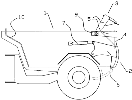
Fig. 1 is a side view of a dump body for an underground truck,
which dump body is provided with a controlled tailgate and a
mechanical tailgate according to an embodiment of the invention, and
on which the closed position of the mechanical tailgate is shown by
continuous lines and its opened position by dash dotted lines,
Fig. 2 is a view from behind of an underground truck, the dump
body of which is provided with the mechanical tailgate
according to an embodiment of the invention, and
Fig. 3 is an enlarged detailed view of the locking of the
mechanical tailgate according to an embodiment of the invention by
means of the controlled tailgate.
Description of anibadiments
Fig. 1 shows a dump body 1 for an underground truck
provided with on one hand a known, controlled tailgate 2 and
on the other hand with a mechanical tailgate 3 according to
an embodiment of the invention. By mechanical tailgate is meant a non-
controlled tailgate, i.e. the gate is arranged to be raised by
the forces exertedby the load on the tailgate 3 when the load
is Unloaded by, where appropriate, an ejector gate 10, and to
return to its closed position by gravity. By controlled
tailgate is meant a tailgate which by some means or devices is
opened and closed on demand.
Although, in the description below, the inventive object is
called a mechanical tailgate, it should be mentioned that said

CA 02661076 2012-10-18
29312-60
4
tailgate also can be controlled by for instance one or several
hydraulic cylinders or by other means for opening and closing
the tailgate, as will be described more closely below.
The mechanical tailgate 3 comprises an essentially vertical
tailgate sheet 4 and two essentially horizontal lifting arms
5, side walls and necessary reinforcement and fastening means
to reinforce, hold and attach the tailgate sheet 4 at the
lifting arms 5. In some embodiments of the invention either the
lifting arms 5 or the tailgate sheet 4 are pivotably arranged at the
dump body 1 by suitable hinging means 9, which, in some embodiments,
are arranged at the side walls of the dump body 1 and close to
its rear upper edge. In some eMbodiments the lifting arms 5
are pivotably arranged at the dump body L. In the case the
tailgate sheet 4 is pivotably arranged the lifting arms 5 form
an elongation of the rear portion of the side walls of the
dump body 1.
The controlled tailgate 2 is, as is known by the artisan,
.pivotably. .attachedtothe-side-walls of the dump body 1 by
,brackets 6 for opening and closing the controlled tailgate.
Opening and closing.of.the controlled tailgate 2 is
preferably, done as is. known, by at least a device 7 such as
hydraulic cylinders
In Fig. 1 the opened position of the Mechanical tailgate 3, i.e.
the unloading position of a truck with a dump body comprising an
ejector gate, for instance, is shown by dash dotted lines. When
unloading a truck with a dump body comprising an ejector gate
provided with the mechanical tailgate 3 according to the
invention the controlled tailgate 2 is first lowered and the
ejector gate 10 pushes the load out of the dump body. The force
exerted by the ejector gate on the load will, depending on its
height, lift and open the mechanical tailgate, and the mechanical
tailgate will fall back by gravity to its closed, original
position,

CA 02661076 2012-10-18
29312-60
when the load no longer effect the tailgate. In this position
the flanges of-the mechanical tailgate 3 rest against
corresponding side edges of the dump body 1.
As can be inferred from Fig. 2 the dump body 1 is so designed
5 that a lower part of the dump body is placed between one or
several wheel units 8, and the controlled tailgate 2 is
designed to fit the shape of the dump body, which means that a
lower part of the tailgate 2, in its unloading position, is
adapted to be placed between the rear wheel unit 8. See Fig.
1.
The detailed view in Fig. 3 shows the mechanical tailgate 3
and the controlled tailgate 2 in closed position. In some
embodiments of the invention the tailgate sheet 4 and
the controlled tailgate 2 overlap each other in such a way
that the lower edge of the tailgate sheet 4 is placed on the
inside of the upper edge of the controlled tailgate 2, seen in
the rear direction of the dump body. In some embodiments the
upper edge of the controlled tailgate 2 rests against the
tailgate sheet 4 and a small distance upwards from the lower
edge of the tailgate sheet. Other clamping mechanisms of the
mechanical tailgate 3 are possible, in particular in the case
the mechanical tailgate is provided with operiihg and closing
means. These opening and closing means can have the form of
-
. hydraulic cylinders or for instance bars (not shown) which are
arranged to operate between the brackets 6 of the controlled
tailgate 2 and the lifting arms 5 of the mechanical tailgate 3
or on the tailgate sheet 4.
By means of the mechanical tailgate 3 according to an embodiment of
the invention it may be possible to fill up the dead space which
otherwise will be present since the rear ends of the side

CA 02661076 2009-02-18
29312-60
6
walls of the dump body 1 slope obliquely towards the
controlled tailgate 2.

Representative Drawing
A single figure which represents the drawing illustrating the invention.
Administrative Status

For a clearer understanding of the status of the application/patent presented on this page, the site Disclaimer , as well as the definitions for Patent , Administrative Status , Maintenance Fee  and Payment History  should be consulted.

Administrative Status

Title Date
Forecasted Issue Date 2013-07-09
(86) PCT Filing Date 2007-08-24
(87) PCT Publication Date 2008-03-13
(85) National Entry 2009-02-18
Examination Requested 2011-06-09
(45) Issued 2013-07-09
Deemed Expired 2016-08-24

Abandonment History

There is no abandonment history.

Payment History

Fee Type Anniversary Year Due Date Amount Paid Paid Date
Application Fee $400.00 2009-02-18
Maintenance Fee - Application - New Act 2 2009-08-24 $100.00 2009-07-09
Maintenance Fee - Application - New Act 3 2010-08-24 $100.00 2010-07-07
Request for Examination $800.00 2011-06-09
Maintenance Fee - Application - New Act 4 2011-08-24 $100.00 2011-07-05
Maintenance Fee - Application - New Act 5 2012-08-24 $200.00 2012-07-10
Final Fee $300.00 2013-04-26
Maintenance Fee - Patent - New Act 6 2013-08-26 $200.00 2013-07-09
Maintenance Fee - Patent - New Act 7 2014-08-25 $200.00 2014-08-18
Owners on Record

Note: Records showing the ownership history in alphabetical order.

Current Owners on Record
ATLAS COPCO ROCK DRILLS AB
Past Owners on Record
RYDSTROEM, LARS
Past Owners that do not appear in the "Owners on Record" listing will appear in other documentation within the application.
Documents

To view selected files, please enter reCAPTCHA code :


To view images, click a link in the Document Description column. To download the documents, select one or more checkboxes in the first column and then click the "Download Selected in PDF format (Zip Archive)" or the "Download Selected as Single PDF" button.

List of published and non-published patent-specific documents on the CPD .

If you have any difficulty accessing content, you can call the Client Service Centre at 1-866-997-1936 or send them an e-mail at CIPO Client Service Centre.


Document
Description 
Date
(yyyy-mm-dd) 
Number of pages   Size of Image (KB) 
Representative Drawing 2009-05-13 1 7
Abstract 2009-02-18 1 62
Claims 2009-02-18 2 50
Drawings 2009-02-18 3 20
Description 2009-02-18 6 201
Cover Page 2009-06-22 2 47
Description 2009-02-19 7 232
Claims 2009-02-19 2 49
Description 2012-10-18 7 242
Representative Drawing 2013-06-17 1 8
Cover Page 2013-06-17 1 44
Description 2012-09-28 7 235
Claims 2012-09-28 2 53
PCT 2009-02-18 5 191
Assignment 2009-02-18 3 109
Prosecution-Amendment 2009-02-18 13 418
Prosecution-Amendment 2011-06-09 2 79
Prosecution-Amendment 2012-10-18 7 298
Prosecution-Amendment 2012-02-14 2 83
Prosecution-Amendment 2012-03-29 2 76
Prosecution-Amendment 2012-09-28 10 368
Correspondence 2013-04-26 2 68