Sélection de la langue

Search

Sommaire du brevet 2661076 

Énoncé de désistement de responsabilité concernant l'information provenant de tiers

Une partie des informations de ce site Web a été fournie par des sources externes. Le gouvernement du Canada n'assume aucune responsabilité concernant la précision, l'actualité ou la fiabilité des informations fournies par les sources externes. Les utilisateurs qui désirent employer cette information devraient consulter directement la source des informations. Le contenu fourni par les sources externes n'est pas assujetti aux exigences sur les langues officielles, la protection des renseignements personnels et l'accessibilité.

Disponibilité de l'Abrégé et des Revendications

L'apparition de différences dans le texte et l'image des Revendications et de l'Abrégé dépend du moment auquel le document est publié. Les textes des Revendications et de l'Abrégé sont affichés :

  • lorsque la demande peut être examinée par le public;
  • lorsque le brevet est émis (délivrance).
(12) Brevet: (11) CA 2661076
(54) Titre français: HAYON MECANIQUE
(54) Titre anglais: MECHANICAL TAILGATE
Statut: Réputé périmé
Données bibliographiques
(51) Classification internationale des brevets (CIB):
  • B62D 33/03 (2006.01)
(72) Inventeurs :
  • RYDSTROEM, LARS (Suède)
(73) Titulaires :
  • ATLAS COPCO ROCK DRILLS AB (Suède)
(71) Demandeurs :
  • ATLAS COPCO ROCK DRILLS AB (Suède)
(74) Agent: FETHERSTONHAUGH & CO.
(74) Co-agent:
(45) Délivré: 2013-07-09
(86) Date de dépôt PCT: 2007-08-24
(87) Mise à la disponibilité du public: 2008-03-13
Requête d'examen: 2011-06-09
Licence disponible: S.O.
(25) Langue des documents déposés: Anglais

Traité de coopération en matière de brevets (PCT): Oui
(86) Numéro de la demande PCT: PCT/SE2007/000748
(87) Numéro de publication internationale PCT: WO2008/030155
(85) Entrée nationale: 2009-02-18

(30) Données de priorité de la demande:
Numéro de la demande Pays / territoire Date
0601827-9 Suède 2006-09-06

Abrégés

Abrégé français

L'invention concerne un hayon mécanique (3) pour une benne basculante (1) d'un camion souterrain, l'objet du hayon mécanique étant d'augmenter la capacité de charge de la benne basculante, lequel hayon mécanique est disposé de manière à pouvoir pivoter entre une position ouverte et une position fermée, et comprenant une feuille de hayon (4) fixée à deux bras de levage (5) qui sont fixés de manière à pouvoir pivoter sur la benne basculante (1) ; la benne basculante (1) comprend également un hayon contrôlé (2) disposé de manière à être contrôlé entre la position ouverte et la position fermée de la benne basculante, le mouvement d'ouverture et de fermeture du hayon contrôlé (2) étant effectué sous la forme d'un mouvement circulaire. Dans la position fermée du hayon mécanique (3) et du hayon contrôlé (2), la feuille de hayon (4) et le hayon contrôlé (2) sont disposés de manière à se chevaucher l'un l'autre de manière à ce qu'un bord inférieur de la feuille de hayon (4) soit placée à l'intérieur du bord supérieur du hayon contrôlé (2) pour verrouiller la feuille de hayon (4) vers le hayon contrôlé (2).


Abrégé anglais

A mechanical tailgate (3) for a dump body (1) of an underground truck, the purpose of the mechanical tailgate is to increase the loading capacity of the dump body, which mechanical tailgate is pivotably arranged between an opened and a closed position, comprising a tailgate sheet (4) attached to two lifting arms (5), which are pivotably arranged to the dump body (1), the dump body (1) comprises also a controlled tailgate (2) arranged to be controlled between opened and closed position of the dump body, the opening and closing movement of the controlled tailgate (2) is effected in the form of a circular movement. In the closed position of the mechanical tailgate (3) and the controlled tailgate (2), the tailgate sheet (4) and the controlled tailgate (2) are arranged to be positioned overlapping each other in such a way that a lower edge of the tailgate sheet (4) is placed on the inside of an upper edge of the controlled tailgate (2) for locking the tailgate sheet (4) towards the controlled tailgate (2).

Revendications

Note : Les revendications sont présentées dans la langue officielle dans laquelle elles ont été soumises.


7
CLAIMS:

1. A mechanical tailgate for a dump body comprising at
least a rear wheel unit of an underground truck, the purpose of
the mechanical tailgate is to increase the loading capacity of
the dump body, which mechanical tailgate is pivotably arranged
between an opened and a closed position, comprising a tailgate
sheet attached to two lifting arms, which are pivotably
arranged to the dump body, the dump body comprises also a
controlled tailgate arranged to be controlled between opened
and closed position of the dump body, the opening and closing
movement of the controlled tailgate is effected in the form of
a circular movement, wherein the controlled tailgate, in its
unloading position, is adapted to be placed between the rear
wheel unit, and wherein, in the closed position of the
mechanical tailgate and the controlled tailgate, the tailgate
sheet and the controlled tailgate are arranged to be positioned
overlapping each other in such a way that a lower edge of the
tailgate sheet is placed on the inside of an upper edge of the
controlled tailgate for locking the tailgate sheet towards the
controlled tailgate.
2. The mechanical tailgate according to claim 1, wherein
at least one device is provided for opening and closing,
respectively, the controlled tailgate.
3. The mechanical tailgate according to claim 2, wherein
the device for opening and closing, respectively, of the
controlled tailgate comprises at least one hydraulic cylinder.
4. The mechanical tailgate according to claim 3, wherein
the device for opening, and closing, respectively, the


8

controlled tailgate comprises at least one bar operable between
a bracket of the controlled tailgate and the lifting arm of the
mechanical tailgate.
5. The mechanical tailgate according to claim 1, wherein
the underground truck is a truck with a dump body comprising an
ejector gate.
6. A dump body of an underground truck, wherein the dump
body is provided with a mechanical tailgate according to any
one of claims 1 - 4.

Description

Note : Les descriptions sont présentées dans la langue officielle dans laquelle elles ont été soumises.

CA 02661076 2012-10-18
29312-60
1
MECHANICAL TAILGATE
Field of the invention
The invention relates to a mechanical tailgate for a dump body
of an underground truck. The invention also relates to a dump
body having such mechanical tailgate.
Background of the invention
To be able to unload a dump body of an underground truck, for
instance, the dump body is provided with a controlled tailgate
adapted to be moved between a closed and an opened position.
The dump body can either be pivotably or fixed arranged at the
underground truck. When the dump body is fixed arranged at the
underground truck a so called ejector gate is placed at the
front end of the dump body and adapted to eject the cargo from
the dump body when the controlled tailgate is in its opened
position.
Particularly, at a type of underground truck with a dump body
comprising an ejector gate, which is provided with a fixed dump
body and which is used for unloading cargo in areas with low
ceiling height, in which area a pivotable dump body can not be
used, the controlled tailgate moves downward towards the rear
wheel unit, when the tailgate opens for unloading ore.
When the controlled tailgate of a truck with a dump body
comprising an ejector gate of the above-mentioned type is
opened a problem arises in that the available distance of
motion for opening the controlled tailgate is limited, i.e. the
height from the ground to the bottom of the dump body is

CA 02661076 2012-10-18
29312-60
2
limited. This results in that the cargo/ore that can be loaded
on the dump body is limited to height of controlled tailgate.
The side walls of the dump body are usually higher than the
height of controlled tailgate in its closed position.
Therefore, the rear portion of the side walls of the dump body
usually inclines obliquely backward towards the upper edge of
the controlled tailgate, whereby a dead space is formed where
no cargo can be loaded.
A way of reducing this problem at known trucks with a dump body
comprising an ejector gate is to design the controlled tailgate
in the form of a circular arc, and to let a portion of the
lower part of the arc-shaped, controlled tailgate to move in a
circular movement in between the rear wheel unit of the truck.
In this way it is possible to increase the height of the
controlled tailgate and thereby the loading capacity of the
dump body. However, the height of the tailgate remains lower
than the height of the side walls of the dump body.
It has now turned out that it would be desirable to increase
the loading capacity of the dump body, preferably by increasing
the height of the tailgate, whereby the side walls of the dump
body may have the same height over its entire length.

CA 02661076 2012-09-28
29312-60
2a
Summary of the invention
According to one broad aspect of the present
invention, there is provided a mechanical tailgate for a dump
body comprising at least a rear wheel unit of an underground
truck, the purpose of the mechanical tailgate is to increase
the loading capacity of the dump body, which mechanical
tailgate is pivotably arranged between an opened and a closed
position, comprising a tailgate sheet attached to two lifting
arms, which are pivotably arranged to the dump body, the dump
body comprises also a controlled tailgate arranged to be
controlled between opened and closed position of the dump body,
the opening and closing movement of the controlled.tailgate is
effected in the form of a circular movement, wherein the
controlled tailgate, in its unloading position, is adapted to
be placed between the rear wheel unit, and wherein, in the
closed position of the mechanical tailgate and the controlled
tailgate, the tailgate sheet and the controlled tailgate are
arranged to be positioned overlapping each other in such a way
that a lower edge of the tailgate sheet is placed on the inside
of an upper edge of the controlled tailgate for locking the
tailgate sheet towards the controlled tailgate.
Some embodiments of the invention may eliminate or at
least reduce the problem with the prior art and to arrange a
mechanical tailgate, by which it is possible to increase the
loading capacity of the dump body.

CA 02661076 2012-10-18
29312-60
3
Brief description of the drawings
The invention is more closely described below with reference
to the accompanying drawings which show a non-limiting example
of the invention and on which:
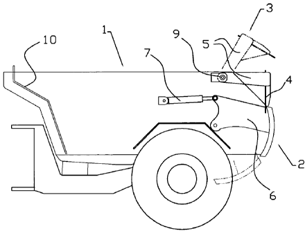
Fig. 1 is a side view of a dump body for an underground truck,
which dump body is provided with a controlled tailgate and a
mechanical tailgate according to an embodiment of the invention, and
on which the closed position of the mechanical tailgate is shown by
continuous lines and its opened position by dash dotted lines,
Fig. 2 is a view from behind of an underground truck, the dump
body of which is provided with the mechanical tailgate
according to an embodiment of the invention, and
Fig. 3 is an enlarged detailed view of the locking of the
mechanical tailgate according to an embodiment of the invention by
means of the controlled tailgate.
Description of anibadiments
Fig. 1 shows a dump body 1 for an underground truck
provided with on one hand a known, controlled tailgate 2 and
on the other hand with a mechanical tailgate 3 according to
an embodiment of the invention. By mechanical tailgate is meant a non-
controlled tailgate, i.e. the gate is arranged to be raised by
the forces exertedby the load on the tailgate 3 when the load
is Unloaded by, where appropriate, an ejector gate 10, and to
return to its closed position by gravity. By controlled
tailgate is meant a tailgate which by some means or devices is
opened and closed on demand.
Although, in the description below, the inventive object is
called a mechanical tailgate, it should be mentioned that said

CA 02661076 2012-10-18
29312-60
4
tailgate also can be controlled by for instance one or several
hydraulic cylinders or by other means for opening and closing
the tailgate, as will be described more closely below.
The mechanical tailgate 3 comprises an essentially vertical
tailgate sheet 4 and two essentially horizontal lifting arms
5, side walls and necessary reinforcement and fastening means
to reinforce, hold and attach the tailgate sheet 4 at the
lifting arms 5. In some embodiments of the invention either the
lifting arms 5 or the tailgate sheet 4 are pivotably arranged at the
dump body 1 by suitable hinging means 9, which, in some embodiments,
are arranged at the side walls of the dump body 1 and close to
its rear upper edge. In some eMbodiments the lifting arms 5
are pivotably arranged at the dump body L. In the case the
tailgate sheet 4 is pivotably arranged the lifting arms 5 form
an elongation of the rear portion of the side walls of the
dump body 1.
The controlled tailgate 2 is, as is known by the artisan,
.pivotably. .attachedtothe-side-walls of the dump body 1 by
,brackets 6 for opening and closing the controlled tailgate.
Opening and closing.of.the controlled tailgate 2 is
preferably, done as is. known, by at least a device 7 such as
hydraulic cylinders
In Fig. 1 the opened position of the Mechanical tailgate 3, i.e.
the unloading position of a truck with a dump body comprising an
ejector gate, for instance, is shown by dash dotted lines. When
unloading a truck with a dump body comprising an ejector gate
provided with the mechanical tailgate 3 according to the
invention the controlled tailgate 2 is first lowered and the
ejector gate 10 pushes the load out of the dump body. The force
exerted by the ejector gate on the load will, depending on its
height, lift and open the mechanical tailgate, and the mechanical
tailgate will fall back by gravity to its closed, original
position,

CA 02661076 2012-10-18
29312-60
when the load no longer effect the tailgate. In this position
the flanges of-the mechanical tailgate 3 rest against
corresponding side edges of the dump body 1.
As can be inferred from Fig. 2 the dump body 1 is so designed
5 that a lower part of the dump body is placed between one or
several wheel units 8, and the controlled tailgate 2 is
designed to fit the shape of the dump body, which means that a
lower part of the tailgate 2, in its unloading position, is
adapted to be placed between the rear wheel unit 8. See Fig.
1.
The detailed view in Fig. 3 shows the mechanical tailgate 3
and the controlled tailgate 2 in closed position. In some
embodiments of the invention the tailgate sheet 4 and
the controlled tailgate 2 overlap each other in such a way
that the lower edge of the tailgate sheet 4 is placed on the
inside of the upper edge of the controlled tailgate 2, seen in
the rear direction of the dump body. In some embodiments the
upper edge of the controlled tailgate 2 rests against the
tailgate sheet 4 and a small distance upwards from the lower
edge of the tailgate sheet. Other clamping mechanisms of the
mechanical tailgate 3 are possible, in particular in the case
the mechanical tailgate is provided with operiihg and closing
means. These opening and closing means can have the form of
-
. hydraulic cylinders or for instance bars (not shown) which are
arranged to operate between the brackets 6 of the controlled
tailgate 2 and the lifting arms 5 of the mechanical tailgate 3
or on the tailgate sheet 4.
By means of the mechanical tailgate 3 according to an embodiment of
the invention it may be possible to fill up the dead space which
otherwise will be present since the rear ends of the side

CA 02661076 2009-02-18
29312-60
6
walls of the dump body 1 slope obliquely towards the
controlled tailgate 2.

Dessin représentatif
Une figure unique qui représente un dessin illustrant l'invention.
États administratifs

Pour une meilleure compréhension de l'état de la demande ou brevet qui figure sur cette page, la rubrique Mise en garde , et les descriptions de Brevet , États administratifs , Taxes périodiques et Historique des paiements devraient être consultées.

États administratifs

Titre Date
Date de délivrance prévu 2013-07-09
(86) Date de dépôt PCT 2007-08-24
(87) Date de publication PCT 2008-03-13
(85) Entrée nationale 2009-02-18
Requête d'examen 2011-06-09
(45) Délivré 2013-07-09
Réputé périmé 2016-08-24

Historique d'abandonnement

Il n'y a pas d'historique d'abandonnement

Historique des paiements

Type de taxes Anniversaire Échéance Montant payé Date payée
Le dépôt d'une demande de brevet 400,00 $ 2009-02-18
Taxe de maintien en état - Demande - nouvelle loi 2 2009-08-24 100,00 $ 2009-07-09
Taxe de maintien en état - Demande - nouvelle loi 3 2010-08-24 100,00 $ 2010-07-07
Requête d'examen 800,00 $ 2011-06-09
Taxe de maintien en état - Demande - nouvelle loi 4 2011-08-24 100,00 $ 2011-07-05
Taxe de maintien en état - Demande - nouvelle loi 5 2012-08-24 200,00 $ 2012-07-10
Taxe finale 300,00 $ 2013-04-26
Taxe de maintien en état - brevet - nouvelle loi 6 2013-08-26 200,00 $ 2013-07-09
Taxe de maintien en état - brevet - nouvelle loi 7 2014-08-25 200,00 $ 2014-08-18
Titulaires au dossier

Les titulaires actuels et antérieures au dossier sont affichés en ordre alphabétique.

Titulaires actuels au dossier
ATLAS COPCO ROCK DRILLS AB
Titulaires antérieures au dossier
RYDSTROEM, LARS
Les propriétaires antérieurs qui ne figurent pas dans la liste des « Propriétaires au dossier » apparaîtront dans d'autres documents au dossier.
Documents

Pour visionner les fichiers sélectionnés, entrer le code reCAPTCHA :


Pour visualiser une image, cliquer sur un lien dans la colonne description du document. Pour télécharger l'image (les images), cliquer l'une ou plusieurs cases à cocher dans la première colonne et ensuite cliquer sur le bouton "Télécharger sélection en format PDF (archive Zip)" ou le bouton "Télécharger sélection (en un fichier PDF fusionné)".

Liste des documents de brevet publiés et non publiés sur la BDBC .

Si vous avez des difficultés à accéder au contenu, veuillez communiquer avec le Centre de services à la clientèle au 1-866-997-1936, ou envoyer un courriel au Centre de service à la clientèle de l'OPIC.


Description du
Document 
Date
(yyyy-mm-dd) 
Nombre de pages   Taille de l'image (Ko) 
Dessins représentatifs 2009-05-13 1 7
Abrégé 2009-02-18 1 62
Revendications 2009-02-18 2 50
Dessins 2009-02-18 3 20
Description 2009-02-18 6 201
Page couverture 2009-06-22 2 47
Description 2009-02-19 7 232
Revendications 2009-02-19 2 49
Description 2012-10-18 7 242
Dessins représentatifs 2013-06-17 1 8
Page couverture 2013-06-17 1 44
Description 2012-09-28 7 235
Revendications 2012-09-28 2 53
PCT 2009-02-18 5 191
Cession 2009-02-18 3 109
Poursuite-Amendment 2009-02-18 13 418
Poursuite-Amendment 2011-06-09 2 79
Poursuite-Amendment 2012-10-18 7 298
Poursuite-Amendment 2012-02-14 2 83
Poursuite-Amendment 2012-03-29 2 76
Poursuite-Amendment 2012-09-28 10 368
Correspondance 2013-04-26 2 68