Language selection

Search

Patent 2680755 Summary

Third-party information liability

Some of the information on this Web page has been provided by external sources. The Government of Canada is not responsible for the accuracy, reliability or currency of the information supplied by external sources. Users wishing to rely upon this information should consult directly with the source of the information. Content provided by external sources is not subject to official languages, privacy and accessibility requirements.

Claims and Abstract availability

Any discrepancies in the text and image of the Claims and Abstract are due to differing posting times. Text of the Claims and Abstract are posted:

  • At the time the application is open to public inspection;
  • At the time of issue of the patent (grant).
(12) Patent: (11) CA 2680755
(54) English Title: METHOD AND DEVICE FOR CONNECTING A TANKER AT SEA
(54) French Title: PROCEDE ET DISPOSITIF DE COUPLAGE D'UN PETROLIER EN MER
Status: Deemed expired
Bibliographic Data
(51) International Patent Classification (IPC):
  • B63B 27/24 (2006.01)
(72) Inventors :
  • HANSEN, HANS RICHARD (Norway)
  • NORDTVEIT, REINERT (Norway)
(73) Owners :
  • TEEKAY NORWAY AS (Norway)
(71) Applicants :
  • TEEKAY NORWAY AS (Norway)
(74) Agent: RIDOUT & MAYBEE LLP
(74) Associate agent:
(45) Issued: 2014-09-09
(86) PCT Filing Date: 2008-03-11
(87) Open to Public Inspection: 2008-10-23
Examination requested: 2013-02-06
Availability of licence: N/A
(25) Language of filing: English

Patent Cooperation Treaty (PCT): Yes
(86) PCT Filing Number: PCT/NO2008/000088
(87) International Publication Number: WO2008/127117
(85) National Entry: 2009-09-14

(30) Application Priority Data:
Application No. Country/Territory Date
20071395 Norway 2007-03-15

Abstracts

English Abstract

A method and device for connecting a tanker (1) at a loading facility (2) at sea, in which, after having positioned itself at the loading facility (2), the tanker (1) is connected to a loading hose (4) for fluid to be transferred from the loading facility (2) to the tanker (1), and in which the stern (20) of the tanker (1) is turned towards the loading facility (2), the tanker (1) being provided, at its stern (20), with propulsion machinery (16) steerable in the horizontal plane, and in which the loading hose (4) is then connected to a cargo manifold (10) positioned at the stern (20) of the tanker (1).


French Abstract

L'invention concerne un procédé et un dispositif de couplage d'un pétrolier (1) à une installation de chargement (2) en mer dans lequel, après s'être positionné au niveau de l'installation de chargement (2), le pétrolier (1) est couplé à une conduite de chargement (4) pour transférer un fluide de l'installation de chargement (2) au pétrolier (1), et dans lequel la poupe (20) du pétrolier (1) est tournée vers l'installation de chargement (2), le pétrolier (1) étant pourvu, au niveau de sa poupe (20), d'une machinerie de propulsion (16) pouvant être dirigée dans un plan horizontal, et dans lequel la conduite de chargement (4) est ensuite couplée à un distributeur de chargement (10) positionnée au niveau de la poupe (20) du pétrolier (1).

Claims

Note: Claims are shown in the official language in which they were submitted.


6

Claims


1. A method for connecting a tanker (1) to a loading
facility (2) at sea, in which, after having positioned
itself at the loading facility (2), the tanker (1) is
connected to a loading hose (4) for fluid to be
transferred from the loading facility (2) to the
tanker (1), characterized in that the
stern (20) of the tanker (1) is turned towards the
loading facility (2), the tanker (1) being provided,
at its stern (20), with a propulsion propeller (18)
steerable in the horizontal plane, and the loading
hose (4) is then connected to a cargo manifold (10)
positioned at the stern (20) of the tanker (1), after
which the tanker (1) receives cargo from the loading
facility (2).

2. The method in accordance with claim 1, charac-
terized in that the position of the tanker
(1) during the loading is maintained by means of
dynamic positioning.

3. A tanker (1) for connection to a loading facility (2)
at sea, characterized in that at its
stern (20) the tanker (1) is provided with a
propulsion propeller (18) pivotal in the horizontal
plane, and the cargo manifold (10) of the tanker is
arranged near the stern (20) of the tanker (1).

4. The device in accordance with claim 3, charac-
terized in that the tanker (1) is provided
with two or more independently steerable propulsion
propellers (18).


2


5. The device in accordance with claim 4, charac
terized in that the cargo manifold (10) is
on the poop (14) of the tanker (1).

Description

Note: Descriptions are shown in the official language in which they were submitted.


CA 02680755 2009-09-14
WO 2008/127117 PCT/N02008/000088
1

METHOD AND DEVICE FOR CONNECTING A TANKER AT SEA

This invention relates to a method for connecting a tanker at
sea. More particularly, it relates to a method for connecting
a tanker to a loading facility at sea, in which, after having

positioned itself at the loading facility, the tanker is con-
nected to a loading hose for fluid to be transferred from the
loading facility to the tanker. The stern of the tanker is
turned towards the loading facility, the tanker being pro-
vided at its stern with propulsion machinery which is steer-
able in the horizontal plane, after which the loading hose is
connected to a cargo manifold located at the stern of the
tanker.

So-called buoy loading of tankers at sea is used to a consid-
erable extent, for example for loading crude oil from some

fields in the North Sea. The offshore loading facility may
include, for example, a loading buoy or a production ship,
often referred to as an FPSO (Floating Production, Storage
and Offloading) vessel.

Several solutions have been developed, some of which include
mooring of the tanker and connection to a submerged buoy,
whereas, in other solutions, it may be unnecessary to moor
the tanker.

Gradually, so-called bow loading has come into relatively
wide use. The method involves that the tanker to be loaded


CA 02680755 2009-09-14
WO 2008/127117 PCT/N02008/000088
2

moves its bow up to the loading facility. A loading hose is
then passed from the loading facility and connected to the
cargo manifold of the tanker, which is at the bow of the
tanker. During the loading the tanker is held in position by
means of the propulsion machinery of the tanker and rela-
tively powerful thrusters at the bow of the tanker.
However, loading of this kind is relatively vulnerable to
weather, as forces from waves and wind acting on the bow of
the tanker must be balanced by sufficient force from the
thrusters to hold the bow of the tanker in a substantially
fixed position relative to the loading facility. Especially
in the wintertime it happens that loading must be put off be-
cause the effect of the thrusters is not sufficient to ensure
that the bow of the tanker will stay in the right position

during the loading.

Besides, bow manifolds are relatively highly exposed to sea
spray and, thereby, icing in wintertime. This may entail con-
siderable extra work before loading can be started.

The invention has for its object to remedy or reduce at least
one of the drawbacks of the prior art.

The object is achieved according to the invention through the
features which are specified in the description below and in
the claims that follow.

A method in accordance with the invention for the connection
of a tanker to a loading facility at sea, in which, after
having positioned itself at the loading facility, the tanker
is connected to a loading hose for fluid to be transferred
from the loading facility to the tanker, is characterized by
the stern of the ship being turned towards the loading facil-
ity, the tanker being provided, at its stern, with propulsion
machinery which is steerable in the horizontal plane, and the


CA 02680755 2009-09-14
WO 2008/127117 PCT/N02008/000088
3

loading hose then being connected to a cargo manifold which
is located at the stern of the tanker.

With advantage, the tanker is provided with so-called dynamic
positioning, in which a control system calculates, by means
of external navigation signals, any current deviation from a
desired position, the control system seeking to reduce the
deviation by means of the steering and propulsion machinery
of the tanker.

Preferably, the propulsion machinery, which is steerable in
the horizontal plane, includes at least two propellers which
are arranged to be pivoted in the horizontal plane. The pro-
pulsion machinery of tankers of this kind has substantially
greater efficiency than what could possibly be transmitted
via thrusters at the bow.

Thus, matters are well arranged for the tanker to be held in
position by means of the positioning system's control of the
power and relative direction of the propulsion machinery,
while the stern of the tanker is connected to the loading fa-
cility. This is also the case in considerably worse weather

conditions than those under which it is possible to load when
the bow of a tanker is to be held in a particular position.
Preferably, the cargo manifold, which is at the stern of the
tanker, is set back somewhat on the poop of the tanker, in
order for any leakage at the manifold connection to be cap-

tured and directed to a collecting tank.

The loading hose may be formed by known loading hose arrange-
ments and is not limited to a loading hose which is reeled
up, in its inactive position, at the loading facility.

The cargo manifold, which is located at the poop, is well
protected from sea spray and icing during the sailing to the


CA 02680755 2009-09-14
WO 2008/127117 PCT/N02008/000088
4

loading device, which simplifies to a substantial degree the
connecting work in cold periods and in northern waters.

In what follows, there is described a non-limiting example of
a preferred method and embodiment which are visualized in the
accompanying drawings, in which:

Figure 1 shows schematically a side view of a tanker which
is connected to a production ship; and

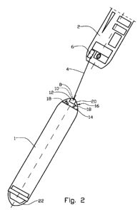
Figure 2 shows schematically a plan view of the tanker and
production ship of figure 1.

In the drawings the reference numeral 1 indicates a tanker,
for example a so-called "shuttle tanker" which is used for
transporting crude oil from sea-based production sites to in-
shore receiving facilities. The tanker 1 is connected to a
loading facility 2 in the form of a production ship by means
of a loading hose 4. The loading hose 4 is formed by, for ex-
ample, a flexible hose which is reeled up, in its inactive
position, on a drum 6 on the production ship 2.

At its free end portion, the loading hose 4 is provided with
a connection 8 which complementarily fits a cargo manifold 10
in a manifold housing 12 on the poop 14 of the tanker 1.

The propulsion machinery 16 of the tanker 1 includes two pro-
pulsion propellers 18 steerable in the horizontal plane,
which are placed at the stern 20 of the ship 1. In figure 2
the propulsion propellers 18 take different directions rela-
tive to the longitudinal axis of the tanker 1. This indicates
that the direction and thrust of the propulsion propellers 18
are controlled to keep the stern 20 of the tanker 1 in a de-
sired position relative to the production ship 2.

In the main, the bow 22 of the tanker 1 may be allowed to


CA 02680755 2009-09-14
WO 2008/127117 PCT/N02008/000088

turn according to the wind and weather. If necessary, the
thrusters 24 of the tanker 1 are used to maintain the direc-
tion of the tanker 1.

When a tanker 1 is to connect to a production ship 2, alter-
5 natively another loading facility, not shown, the stern 20 of
the tanker 1 is turned towards the production ship 2, the

tanker 1 being moved to an appropriate distance from the pro-
duction ship 2.

The stern 20 of the tanker 1 is stabilized in this position
as explained above.

A line, not shown, is shot across from the production vessel
2, whereby the loading hose 4 is gradually pulled across and
connected to the cargo manifold 10 on the poop 14, after

which loading of the tanker 1 may take place.

1s When the loading is finished, the loading hose 4 is discon-
nected from the cargo manifold 10 and pulled back onto the
production ship 2. The tanker 1 then sails to its destina-
tion.

Representative Drawing
A single figure which represents the drawing illustrating the invention.
Administrative Status

For a clearer understanding of the status of the application/patent presented on this page, the site Disclaimer , as well as the definitions for Patent , Administrative Status , Maintenance Fee  and Payment History  should be consulted.

Administrative Status

Title Date
Forecasted Issue Date 2014-09-09
(86) PCT Filing Date 2008-03-11
(87) PCT Publication Date 2008-10-23
(85) National Entry 2009-09-14
Examination Requested 2013-02-06
(45) Issued 2014-09-09
Deemed Expired 2017-03-13

Abandonment History

There is no abandonment history.

Payment History

Fee Type Anniversary Year Due Date Amount Paid Paid Date
Application Fee $400.00 2009-09-14
Maintenance Fee - Application - New Act 2 2010-03-11 $100.00 2009-09-14
Maintenance Fee - Application - New Act 3 2011-03-11 $100.00 2011-01-27
Maintenance Fee - Application - New Act 4 2012-03-12 $100.00 2012-02-14
Maintenance Fee - Application - New Act 5 2013-03-11 $200.00 2013-01-15
Request for Examination $800.00 2013-02-06
Maintenance Fee - Application - New Act 6 2014-03-11 $200.00 2014-01-22
Final Fee $300.00 2014-06-16
Maintenance Fee - Patent - New Act 7 2015-03-11 $200.00 2015-02-16
Owners on Record

Note: Records showing the ownership history in alphabetical order.

Current Owners on Record
TEEKAY NORWAY AS
Past Owners on Record
HANSEN, HANS RICHARD
NORDTVEIT, REINERT
Past Owners that do not appear in the "Owners on Record" listing will appear in other documentation within the application.
Documents

To view selected files, please enter reCAPTCHA code :


To view images, click a link in the Document Description column. To download the documents, select one or more checkboxes in the first column and then click the "Download Selected in PDF format (Zip Archive)" or the "Download Selected as Single PDF" button.

List of published and non-published patent-specific documents on the CPD .

If you have any difficulty accessing content, you can call the Client Service Centre at 1-866-997-1936 or send them an e-mail at CIPO Client Service Centre.


Document
Description 
Date
(yyyy-mm-dd) 
Number of pages   Size of Image (KB) 
Drawings 2009-09-14 2 21
Claims 2009-09-14 2 44
Abstract 2009-09-14 1 56
Description 2009-09-14 5 176
Representative Drawing 2009-11-12 1 4
Cover Page 2009-11-24 2 38
Cover Page 2014-08-18 2 38
Assignment 2009-09-14 5 118
PCT 2009-09-14 11 344
Prosecution-Amendment 2009-09-14 3 74
Fees 2011-01-27 1 35
Prosecution-Amendment 2013-02-06 2 86
Correspondence 2014-06-16 1 54