Sélection de la langue

Search

Sommaire du brevet 2680755 

Énoncé de désistement de responsabilité concernant l'information provenant de tiers

Une partie des informations de ce site Web a été fournie par des sources externes. Le gouvernement du Canada n'assume aucune responsabilité concernant la précision, l'actualité ou la fiabilité des informations fournies par les sources externes. Les utilisateurs qui désirent employer cette information devraient consulter directement la source des informations. Le contenu fourni par les sources externes n'est pas assujetti aux exigences sur les langues officielles, la protection des renseignements personnels et l'accessibilité.

Disponibilité de l'Abrégé et des Revendications

L'apparition de différences dans le texte et l'image des Revendications et de l'Abrégé dépend du moment auquel le document est publié. Les textes des Revendications et de l'Abrégé sont affichés :

  • lorsque la demande peut être examinée par le public;
  • lorsque le brevet est émis (délivrance).
(12) Brevet: (11) CA 2680755
(54) Titre français: PROCEDE ET DISPOSITIF DE COUPLAGE D'UN PETROLIER EN MER
(54) Titre anglais: METHOD AND DEVICE FOR CONNECTING A TANKER AT SEA
Statut: Réputé périmé
Données bibliographiques
(51) Classification internationale des brevets (CIB):
  • B63B 27/24 (2006.01)
(72) Inventeurs :
  • HANSEN, HANS RICHARD (Norvège)
  • NORDTVEIT, REINERT (Norvège)
(73) Titulaires :
  • TEEKAY NORWAY AS (Norvège)
(71) Demandeurs :
  • TEEKAY NORWAY AS (Norvège)
(74) Agent: RIDOUT & MAYBEE LLP
(74) Co-agent:
(45) Délivré: 2014-09-09
(86) Date de dépôt PCT: 2008-03-11
(87) Mise à la disponibilité du public: 2008-10-23
Requête d'examen: 2013-02-06
Licence disponible: S.O.
(25) Langue des documents déposés: Anglais

Traité de coopération en matière de brevets (PCT): Oui
(86) Numéro de la demande PCT: PCT/NO2008/000088
(87) Numéro de publication internationale PCT: WO2008/127117
(85) Entrée nationale: 2009-09-14

(30) Données de priorité de la demande:
Numéro de la demande Pays / territoire Date
20071395 Norvège 2007-03-15

Abrégés

Abrégé français

L'invention concerne un procédé et un dispositif de couplage d'un pétrolier (1) à une installation de chargement (2) en mer dans lequel, après s'être positionné au niveau de l'installation de chargement (2), le pétrolier (1) est couplé à une conduite de chargement (4) pour transférer un fluide de l'installation de chargement (2) au pétrolier (1), et dans lequel la poupe (20) du pétrolier (1) est tournée vers l'installation de chargement (2), le pétrolier (1) étant pourvu, au niveau de sa poupe (20), d'une machinerie de propulsion (16) pouvant être dirigée dans un plan horizontal, et dans lequel la conduite de chargement (4) est ensuite couplée à un distributeur de chargement (10) positionnée au niveau de la poupe (20) du pétrolier (1).


Abrégé anglais

A method and device for connecting a tanker (1) at a loading facility (2) at sea, in which, after having positioned itself at the loading facility (2), the tanker (1) is connected to a loading hose (4) for fluid to be transferred from the loading facility (2) to the tanker (1), and in which the stern (20) of the tanker (1) is turned towards the loading facility (2), the tanker (1) being provided, at its stern (20), with propulsion machinery (16) steerable in the horizontal plane, and in which the loading hose (4) is then connected to a cargo manifold (10) positioned at the stern (20) of the tanker (1).

Revendications

Note : Les revendications sont présentées dans la langue officielle dans laquelle elles ont été soumises.


6

Claims


1. A method for connecting a tanker (1) to a loading
facility (2) at sea, in which, after having positioned
itself at the loading facility (2), the tanker (1) is
connected to a loading hose (4) for fluid to be
transferred from the loading facility (2) to the
tanker (1), characterized in that the
stern (20) of the tanker (1) is turned towards the
loading facility (2), the tanker (1) being provided,
at its stern (20), with a propulsion propeller (18)
steerable in the horizontal plane, and the loading
hose (4) is then connected to a cargo manifold (10)
positioned at the stern (20) of the tanker (1), after
which the tanker (1) receives cargo from the loading
facility (2).

2. The method in accordance with claim 1, charac-
terized in that the position of the tanker
(1) during the loading is maintained by means of
dynamic positioning.

3. A tanker (1) for connection to a loading facility (2)
at sea, characterized in that at its
stern (20) the tanker (1) is provided with a
propulsion propeller (18) pivotal in the horizontal
plane, and the cargo manifold (10) of the tanker is
arranged near the stern (20) of the tanker (1).

4. The device in accordance with claim 3, charac-
terized in that the tanker (1) is provided
with two or more independently steerable propulsion
propellers (18).


2


5. The device in accordance with claim 4, charac
terized in that the cargo manifold (10) is
on the poop (14) of the tanker (1).

Description

Note : Les descriptions sont présentées dans la langue officielle dans laquelle elles ont été soumises.


CA 02680755 2009-09-14
WO 2008/127117 PCT/N02008/000088
1

METHOD AND DEVICE FOR CONNECTING A TANKER AT SEA

This invention relates to a method for connecting a tanker at
sea. More particularly, it relates to a method for connecting
a tanker to a loading facility at sea, in which, after having

positioned itself at the loading facility, the tanker is con-
nected to a loading hose for fluid to be transferred from the
loading facility to the tanker. The stern of the tanker is
turned towards the loading facility, the tanker being pro-
vided at its stern with propulsion machinery which is steer-
able in the horizontal plane, after which the loading hose is
connected to a cargo manifold located at the stern of the
tanker.

So-called buoy loading of tankers at sea is used to a consid-
erable extent, for example for loading crude oil from some

fields in the North Sea. The offshore loading facility may
include, for example, a loading buoy or a production ship,
often referred to as an FPSO (Floating Production, Storage
and Offloading) vessel.

Several solutions have been developed, some of which include
mooring of the tanker and connection to a submerged buoy,
whereas, in other solutions, it may be unnecessary to moor
the tanker.

Gradually, so-called bow loading has come into relatively
wide use. The method involves that the tanker to be loaded


CA 02680755 2009-09-14
WO 2008/127117 PCT/N02008/000088
2

moves its bow up to the loading facility. A loading hose is
then passed from the loading facility and connected to the
cargo manifold of the tanker, which is at the bow of the
tanker. During the loading the tanker is held in position by
means of the propulsion machinery of the tanker and rela-
tively powerful thrusters at the bow of the tanker.
However, loading of this kind is relatively vulnerable to
weather, as forces from waves and wind acting on the bow of
the tanker must be balanced by sufficient force from the
thrusters to hold the bow of the tanker in a substantially
fixed position relative to the loading facility. Especially
in the wintertime it happens that loading must be put off be-
cause the effect of the thrusters is not sufficient to ensure
that the bow of the tanker will stay in the right position

during the loading.

Besides, bow manifolds are relatively highly exposed to sea
spray and, thereby, icing in wintertime. This may entail con-
siderable extra work before loading can be started.

The invention has for its object to remedy or reduce at least
one of the drawbacks of the prior art.

The object is achieved according to the invention through the
features which are specified in the description below and in
the claims that follow.

A method in accordance with the invention for the connection
of a tanker to a loading facility at sea, in which, after
having positioned itself at the loading facility, the tanker
is connected to a loading hose for fluid to be transferred
from the loading facility to the tanker, is characterized by
the stern of the ship being turned towards the loading facil-
ity, the tanker being provided, at its stern, with propulsion
machinery which is steerable in the horizontal plane, and the


CA 02680755 2009-09-14
WO 2008/127117 PCT/N02008/000088
3

loading hose then being connected to a cargo manifold which
is located at the stern of the tanker.

With advantage, the tanker is provided with so-called dynamic
positioning, in which a control system calculates, by means
of external navigation signals, any current deviation from a
desired position, the control system seeking to reduce the
deviation by means of the steering and propulsion machinery
of the tanker.

Preferably, the propulsion machinery, which is steerable in
the horizontal plane, includes at least two propellers which
are arranged to be pivoted in the horizontal plane. The pro-
pulsion machinery of tankers of this kind has substantially
greater efficiency than what could possibly be transmitted
via thrusters at the bow.

Thus, matters are well arranged for the tanker to be held in
position by means of the positioning system's control of the
power and relative direction of the propulsion machinery,
while the stern of the tanker is connected to the loading fa-
cility. This is also the case in considerably worse weather

conditions than those under which it is possible to load when
the bow of a tanker is to be held in a particular position.
Preferably, the cargo manifold, which is at the stern of the
tanker, is set back somewhat on the poop of the tanker, in
order for any leakage at the manifold connection to be cap-

tured and directed to a collecting tank.

The loading hose may be formed by known loading hose arrange-
ments and is not limited to a loading hose which is reeled
up, in its inactive position, at the loading facility.

The cargo manifold, which is located at the poop, is well
protected from sea spray and icing during the sailing to the


CA 02680755 2009-09-14
WO 2008/127117 PCT/N02008/000088
4

loading device, which simplifies to a substantial degree the
connecting work in cold periods and in northern waters.

In what follows, there is described a non-limiting example of
a preferred method and embodiment which are visualized in the
accompanying drawings, in which:

Figure 1 shows schematically a side view of a tanker which
is connected to a production ship; and

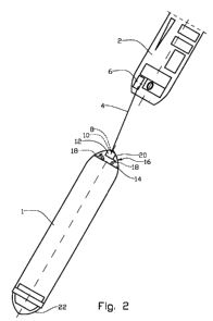
Figure 2 shows schematically a plan view of the tanker and
production ship of figure 1.

In the drawings the reference numeral 1 indicates a tanker,
for example a so-called "shuttle tanker" which is used for
transporting crude oil from sea-based production sites to in-
shore receiving facilities. The tanker 1 is connected to a
loading facility 2 in the form of a production ship by means
of a loading hose 4. The loading hose 4 is formed by, for ex-
ample, a flexible hose which is reeled up, in its inactive
position, on a drum 6 on the production ship 2.

At its free end portion, the loading hose 4 is provided with
a connection 8 which complementarily fits a cargo manifold 10
in a manifold housing 12 on the poop 14 of the tanker 1.

The propulsion machinery 16 of the tanker 1 includes two pro-
pulsion propellers 18 steerable in the horizontal plane,
which are placed at the stern 20 of the ship 1. In figure 2
the propulsion propellers 18 take different directions rela-
tive to the longitudinal axis of the tanker 1. This indicates
that the direction and thrust of the propulsion propellers 18
are controlled to keep the stern 20 of the tanker 1 in a de-
sired position relative to the production ship 2.

In the main, the bow 22 of the tanker 1 may be allowed to


CA 02680755 2009-09-14
WO 2008/127117 PCT/N02008/000088

turn according to the wind and weather. If necessary, the
thrusters 24 of the tanker 1 are used to maintain the direc-
tion of the tanker 1.

When a tanker 1 is to connect to a production ship 2, alter-
5 natively another loading facility, not shown, the stern 20 of
the tanker 1 is turned towards the production ship 2, the

tanker 1 being moved to an appropriate distance from the pro-
duction ship 2.

The stern 20 of the tanker 1 is stabilized in this position
as explained above.

A line, not shown, is shot across from the production vessel
2, whereby the loading hose 4 is gradually pulled across and
connected to the cargo manifold 10 on the poop 14, after

which loading of the tanker 1 may take place.

1s When the loading is finished, the loading hose 4 is discon-
nected from the cargo manifold 10 and pulled back onto the
production ship 2. The tanker 1 then sails to its destina-
tion.

Dessin représentatif
Une figure unique qui représente un dessin illustrant l'invention.
États administratifs

Pour une meilleure compréhension de l'état de la demande ou brevet qui figure sur cette page, la rubrique Mise en garde , et les descriptions de Brevet , États administratifs , Taxes périodiques et Historique des paiements devraient être consultées.

États administratifs

Titre Date
Date de délivrance prévu 2014-09-09
(86) Date de dépôt PCT 2008-03-11
(87) Date de publication PCT 2008-10-23
(85) Entrée nationale 2009-09-14
Requête d'examen 2013-02-06
(45) Délivré 2014-09-09
Réputé périmé 2017-03-13

Historique d'abandonnement

Il n'y a pas d'historique d'abandonnement

Historique des paiements

Type de taxes Anniversaire Échéance Montant payé Date payée
Le dépôt d'une demande de brevet 400,00 $ 2009-09-14
Taxe de maintien en état - Demande - nouvelle loi 2 2010-03-11 100,00 $ 2009-09-14
Taxe de maintien en état - Demande - nouvelle loi 3 2011-03-11 100,00 $ 2011-01-27
Taxe de maintien en état - Demande - nouvelle loi 4 2012-03-12 100,00 $ 2012-02-14
Taxe de maintien en état - Demande - nouvelle loi 5 2013-03-11 200,00 $ 2013-01-15
Requête d'examen 800,00 $ 2013-02-06
Taxe de maintien en état - Demande - nouvelle loi 6 2014-03-11 200,00 $ 2014-01-22
Taxe finale 300,00 $ 2014-06-16
Taxe de maintien en état - brevet - nouvelle loi 7 2015-03-11 200,00 $ 2015-02-16
Titulaires au dossier

Les titulaires actuels et antérieures au dossier sont affichés en ordre alphabétique.

Titulaires actuels au dossier
TEEKAY NORWAY AS
Titulaires antérieures au dossier
HANSEN, HANS RICHARD
NORDTVEIT, REINERT
Les propriétaires antérieurs qui ne figurent pas dans la liste des « Propriétaires au dossier » apparaîtront dans d'autres documents au dossier.
Documents

Pour visionner les fichiers sélectionnés, entrer le code reCAPTCHA :


Pour visualiser une image, cliquer sur un lien dans la colonne description du document. Pour télécharger l'image (les images), cliquer l'une ou plusieurs cases à cocher dans la première colonne et ensuite cliquer sur le bouton "Télécharger sélection en format PDF (archive Zip)" ou le bouton "Télécharger sélection (en un fichier PDF fusionné)".

Liste des documents de brevet publiés et non publiés sur la BDBC .

Si vous avez des difficultés à accéder au contenu, veuillez communiquer avec le Centre de services à la clientèle au 1-866-997-1936, ou envoyer un courriel au Centre de service à la clientèle de l'OPIC.


Description du
Document 
Date
(yyyy-mm-dd) 
Nombre de pages   Taille de l'image (Ko) 
Dessins 2009-09-14 2 21
Revendications 2009-09-14 2 44
Abrégé 2009-09-14 1 56
Description 2009-09-14 5 176
Dessins représentatifs 2009-11-12 1 4
Page couverture 2009-11-24 2 38
Page couverture 2014-08-18 2 38
Cession 2009-09-14 5 118
PCT 2009-09-14 11 344
Poursuite-Amendment 2009-09-14 3 74
Taxes 2011-01-27 1 35
Poursuite-Amendment 2013-02-06 2 86
Correspondance 2014-06-16 1 54