Language selection

Search

Patent 2734659 Summary

Third-party information liability

Some of the information on this Web page has been provided by external sources. The Government of Canada is not responsible for the accuracy, reliability or currency of the information supplied by external sources. Users wishing to rely upon this information should consult directly with the source of the information. Content provided by external sources is not subject to official languages, privacy and accessibility requirements.

Claims and Abstract availability

Any discrepancies in the text and image of the Claims and Abstract are due to differing posting times. Text of the Claims and Abstract are posted:

  • At the time the application is open to public inspection;
  • At the time of issue of the patent (grant).
(12) Patent: (11) CA 2734659
(54) English Title: LUG NUT LOCKING DEVICE
(54) French Title: DISPOSITIF DE VERROUILLAGE D'ECROUS DE ROUE
Status: Granted
Bibliographic Data
(51) International Patent Classification (IPC):
  • F16B 39/02 (2006.01)
  • B60B 30/00 (2006.01)
  • F16B 39/10 (2006.01)
  • F16B 41/00 (2006.01)
(72) Inventors :
  • PRINCE, LENNY (Canada)
(73) Owners :
  • PRINCE, LENNY (Canada)
(71) Applicants :
  • CENTRABALANCE CANADA INC. (Canada)
(74) Agent: CASSAN MACLEAN IP AGENCY INC.
(74) Associate agent:
(45) Issued: 2018-05-01
(22) Filed Date: 2011-03-22
(41) Open to Public Inspection: 2012-09-22
Examination requested: 2016-03-21
Availability of licence: N/A
(25) Language of filing: English

Patent Cooperation Treaty (PCT): No

(30) Application Priority Data: None

Abstracts

English Abstract

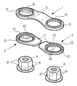
A lug nut locking device, which provides a visual indication of loosening of one of a pair of adjacent nuts includes a locking strip for extending between the nuts, rings on the ends of the strip for mounting the strip on the nuts, teeth in the rings for resisting nut loosening; and a pair of flags with annular bodies for mounting on the nuts beneath the strip, the flag bodies having internal teeth for engaging the nuts, whereby rotation of one of the nuts causes corresponding rotation of its associated flag providing a visual indication that the nut is loosening.


French Abstract

Un dispositif de verrouillage décrous de roue, qui offre une indication visuelle dun desserrement dune des paires décrous adjacents, comprend une bande de blocage pour sétendre entre les écrous, des anneaux sur les extrémités du ruban pour monter le ruban sur les écrous, des dents dans les anneaux pour résister au desserrage de lécrou; et une paire de languettes avec des corps annulaires pour monter sur les écrous sous le ruban, les corps des languettes ayant des dents internes pour mettre en prise les écrous, par lesquels la rotation dun des écrous cause une rotation correspondante de sa languette associée offrant une indication visuelle que lécrou est desserré.

Claims

Note: Claims are shown in the official language in which they were submitted.


CLAIMS:
1. A lug nut locking and indicator device comprising:
an elongated rigid locking strip having a length sufficient to extend between
two adjacent lug nuts;
rings on the ends of the locking strip for placing over the adjacent lug nuts;

first teeth on interior surfaces of said rings for engaging the nuts and
resisting
rotation of the lug nuts relative to said strip and rings;
indicator flags for mounting on and rotation with said lug nuts, in a use
position said flags being axially aligned with said locking strip;
whereby rotation of the adjacent lug nuts is firmly resisted by said first
teeth
on said rings, and, if either of the lug nuts loosens sufficiently to break
the first
teeth, one of the flags rotates to a position out of axial alignment with the
locking
strip where said one of the flags provides a visual indication of nut
loosening.
2. The device of claim 1, wherein said first teeth are integral with and
extend
completely around the interior of each said ring.
3. The device of claim 1, wherein each indicator flag includes an annular
body;
a plurality of second teeth on an interior surface of said annular body for
engaging a
lug nut; and a strip extending radially outwardly from said body.
4. The device of claim 3, wherein each said indicator flag includes an
annular
top flange for engaging the rigid body when the flag is mounted on the lug nut

beneath the rigid body, facilitating rotation of the indicator flag relative
to the locking
strip.
6


5. The
device of claim 4, wherein said rigid body is bowed outwardly away from
the indicator flag, providing unrestricted movement of the flag relative to
the rigid
body.

7

Description

Note: Descriptions are shown in the official language in which they were submitted.


CA 02734659 2011-03-22

LUG NUT LOCKING DEVICE
FIELD OF THE INVENTION

This invention relates to a lug nut locking device, and in particular to a
combination lug nut locking and indicator device.

BACKGROUND OF THE INVENTION

The device of the present invention is intended to lock lug nuts in a
tightened
position, and to provide a visual indication should a lug nut becomes loose.

Lug nut indicator devices, i.e. devices for indicating that a lug nut has
started
to loosen are not new. Examples of such devices are described in CA Patent No.
1,231,564, which issued to Rolf Olsson on January 19, 1988; Canadian Patent

Application No. 2,637,356, filed by Ifor C. Davies on July 11, 2008; US
Patents
Nos. 4,930,951, issued to Mark A. Gilliam on June 5, 1990; 6,158,933, issued
to
Orv Nicholson on December 12, 2000; 6,595,597 and 7,415,888 issued to Michael
Marczynski et al on July 22, 2003 and August 26, 2008, respectively; and the

James C. Adams US Patent Application No. 2009/0060677, published March 5,
2009.

A problem with some of the basic indicator devices described in the above-
listed references is that they merely provide an indication that a lug nut has
started
to loosen. While some of the devices provide resistance to nut loosening, they
are

relatively complicated, and may require substantial nut loosening before
providing a
clear visual signal that loosening has occurred,

1


CA 02734659 2011-03-22

SUMMARY OF THE INVENTION

The present invention provides a relatively simple lug nut locking and
indicator device which firmly resists rotation of a pair of adjacent lug nuts.
However, if loosening of either of the nuts occurs, an indicator flag is
rotated into a

position providing a visual indication that nut loosening has occurred. In
other
words, it takes a substantial force for nut loosening to occur, and if
loosening
happens a visual signal is provided.

In accordance with one aspect, the invention provides a lug nut locking and
indicator device comprising: an elongated rigid locking strip having a length

sufficient to extend between two adjacent lug nuts; rings on the ends of the
locking
strip for placing over the adjacent lug nuts; first teeth on interior surfaces
of said
rings for engaging the nuts and resisting rotation of the lug nuts relative to
said strip
and rings; indicator flags for mounting on and rotation with said lug nuts, in
the use
position said flags being axially aligned with said locking strips; whereby
rotation of

the adjacent lug nuts is firmly resisted by said first teeth on said rings,
and, if either
of the lug nuts loosens sufficiently to break the first teeth, one of the
flags rotates to
a position out of axial alignment with the locking strip where the flag
provides a
visual indication of nut loosening.

BRIEF DESCRIPTION OF THE DRAWINGS

The invention is described below in greater detail with reference to the
accompanying drawings, which illustrate a preferred embodiment of the
invention,
and wherein:

2


CA 02734659 2011-03-22

Figure 1 is an isometric view of a lug nut locking and indicator device in
accordance with the present invention;

Figure 2 is an exploded, isometric view of the lug nut locking and indicator
device of Fig. 1;

Figure 3 is a top view of a locking strip used in the device of Figs 1 and 2;
Figure 4 is a side view of the locking strip of Fig. 3;

Figure 5 is a top view of an indicator flag used in the device of Figs. 1 and
2;
and

Figure 6 is a front view of a vehicle wheel with a plurality of indicator and
locking devices mounted thereon.

DETAILED DESCRIPTION OF THE INVENTION

With reference to Figs. 1 and 2, the basic elements of the lug nut locking and
indicator device of the present invention include a locking strip indicated
generally
at 1 and an indicator flag indicated generally at 2.

As best shown in Figs. 2 - 4, the locking strip 1 includes a rigid, slightly
arched body 3 formed of hard plastic for extending between adjacent lug nuts
4. A
ring 5 is provided at each end of the body 3. The ring 5 is integral with the
body 3
and is defined by a hole through the circular ends of the body and an annular

flange 6 extending upwardly from the body around the hole. A circular row of
teeth
7 extends around the entire inner circumference of the ring 5 for engaging the
corners 8 of the lug nut 4.

3


CA 02734659 2011-03-22

Referring to Figs. 1 and 5, each indicator flag 2 is defined by an annular
body 10 with a short, tapering arm 11 integral with an extending outwardly
from one
side thereof. The top or outer surface of the arm 11 is preferably colored
with a
bright, highly noticeable color such as red. An annular flange 12 extends
upwardly

from around a hole 13 through the body 10. A row of teeth 14 extends
completely
around the periphery of the hole 13 for engaging the corners of the lug nut 4.

As illustrated in Fig. 6, the indicator device is used on adjacent lug nuts 4
securing a wheel 16 on a vehicle (not shown). The lug nuts 4 are mounted on
bolts
17. In use, a pair of indicator flags 2 is mounted first on adjacent, already
tightened

lug nuts 4 with the arms 11 pointing towards each other. The teeth 14 in the
hole
13 lock the flag 12 on the nut 4, i.e. prevent rotation of the flag relative
to the nut 4.
The locking strip 1 is then mounted on the adjacent lug nuts 4 above the
indicator
flags 2, so that the arms 11 of the flags are covered by the body 3 of the
strip (Fig.
6). Because the body 3 of the locking strip is rigid, and the teeth 7 engage
the

corners 8 of the lug nuts 4 rotation of the lug nuts is strongly resisted. If,
however,
the force of the rotation on one of the lug nuts 4 is sufficient to break the
teeth 7 in
one of the rings 5, the indicator flag 2 will rotate with the lug nut to a
position at an
angle or perpendicular to the longitudinal axis of the strip body 3 (e.g. to
the

position shown in phantom between the eight and nine o'clock positions of the

wheel 16). In this position, the flag 2 is no longer aligned with the
longitudinal axis
of the locking strip 1 and thus provides a visual indicator that the locking
nut 4 is
loosening. The flange 10 on the flag 2, and the bowed or arched body 3 reduce

4


CA 02734659 2011-03-22

contact between the strip 1 and the flag 2 to facilitate free rotation of the
flag 2
relative to the strip 1.

In the event that the wheel 16 is to be removed from the vehicle, it is merely
necessary to remove the locking strip 1 and the indicator flags 2. The
internal

diameter of the rings 5 on the ends of the strip 1 and the diameter of the
holes 13 in
the flags 2 are such that the strip 1 and the flags 2 are held in position on
the nuts 4
by friction, but can be pried off with a screwdriver or other tool.

Thus, there has been described a relatively simple lug nut locking and
indicator device, which strongly resists rotation of a pair of adjacent lug
nuts.

However, if rotation i.e. loosening of one of the lug nuts should occur, the
device
provides a visual indication of the event.

5

Representative Drawing
A single figure which represents the drawing illustrating the invention.
Administrative Status

For a clearer understanding of the status of the application/patent presented on this page, the site Disclaimer , as well as the definitions for Patent , Administrative Status , Maintenance Fee  and Payment History  should be consulted.

Administrative Status

Title Date
Forecasted Issue Date 2018-05-01
(22) Filed 2011-03-22
(41) Open to Public Inspection 2012-09-22
Examination Requested 2016-03-21
(45) Issued 2018-05-01

Abandonment History

Abandonment Date Reason Reinstatement Date
2013-03-22 FAILURE TO PAY APPLICATION MAINTENANCE FEE 2013-09-19

Maintenance Fee

Last Payment of $125.00 was received on 2024-03-19


 Upcoming maintenance fee amounts

Description Date Amount
Next Payment if standard fee 2025-03-24 $347.00
Next Payment if small entity fee 2025-03-24 $125.00

Note : If the full payment has not been received on or before the date indicated, a further fee may be required which may be one of the following

  • the reinstatement fee;
  • the late payment fee; or
  • additional fee to reverse deemed expiry.

Patent fees are adjusted on the 1st of January every year. The amounts above are the current amounts if received by December 31 of the current year.
Please refer to the CIPO Patent Fees web page to see all current fee amounts.

Payment History

Fee Type Anniversary Year Due Date Amount Paid Paid Date
Application Fee $200.00 2011-03-22
Reinstatement: Failure to Pay Application Maintenance Fees $200.00 2013-09-19
Maintenance Fee - Application - New Act 2 2013-03-22 $50.00 2013-09-19
Maintenance Fee - Application - New Act 3 2014-03-24 $50.00 2014-03-21
Maintenance Fee - Application - New Act 4 2015-03-23 $50.00 2015-03-19
Request for Examination $400.00 2016-03-21
Maintenance Fee - Application - New Act 5 2016-03-22 $100.00 2016-03-21
Registration of a document - section 124 $100.00 2016-04-12
Maintenance Fee - Application - New Act 6 2017-03-22 $100.00 2017-03-22
Final Fee $150.00 2018-03-14
Maintenance Fee - Application - New Act 7 2018-03-22 $100.00 2018-03-14
Maintenance Fee - Patent - New Act 8 2019-03-22 $100.00 2019-03-21
Maintenance Fee - Patent - New Act 9 2020-03-23 $100.00 2020-04-01
Maintenance Fee - Patent - New Act 10 2021-03-22 $125.00 2021-03-18
Maintenance Fee - Patent - New Act 11 2022-03-22 $125.00 2022-03-22
Maintenance Fee - Patent - New Act 12 2023-03-22 $125.00 2023-03-20
Maintenance Fee - Patent - New Act 13 2024-03-22 $125.00 2024-03-19
Owners on Record

Note: Records showing the ownership history in alphabetical order.

Current Owners on Record
PRINCE, LENNY
Past Owners on Record
CENTRABALANCE CANADA INC.
Past Owners that do not appear in the "Owners on Record" listing will appear in other documentation within the application.
Documents

To view selected files, please enter reCAPTCHA code :


To view images, click a link in the Document Description column. To download the documents, select one or more checkboxes in the first column and then click the "Download Selected in PDF format (Zip Archive)" or the "Download Selected as Single PDF" button.

List of published and non-published patent-specific documents on the CPD .

If you have any difficulty accessing content, you can call the Client Service Centre at 1-866-997-1936 or send them an e-mail at CIPO Client Service Centre.


Document
Description 
Date
(yyyy-mm-dd) 
Number of pages   Size of Image (KB) 
Abstract 2011-03-22 1 14
Description 2011-03-22 5 157
Claims 2011-03-22 2 38
Drawings 2011-03-22 2 58
Representative Drawing 2011-11-17 1 13
Cover Page 2012-09-25 1 39
Claims 2016-04-13 2 36
Assignment 2011-03-22 2 67
Correspondence 2011-04-08 2 66
Amendment 2017-09-06 2 57
Claims 2017-09-06 2 34
Maintenance Fee Payment 2018-03-14 1 33
Final Fee 2018-03-14 1 25
Representative Drawing 2018-04-04 1 12
Cover Page 2018-04-04 2 41
Correspondence 2011-04-04 1 21
Assignment 2011-05-04 3 108
Maintenance Fee Payment 2019-03-21 1 33
Request for Examination 2016-03-21 1 27
Office Letter 2019-09-20 1 34
Fees 2013-09-19 1 33
Fees 2016-03-21 1 33
Fees 2014-03-21 1 33
Amendment 2016-04-13 2 61
Maintenance Fee Payment 2017-03-22 1 33
Examiner Requisition 2017-03-27 3 134