Sélection de la langue

Search

Sommaire du brevet 2734659 

Énoncé de désistement de responsabilité concernant l'information provenant de tiers

Une partie des informations de ce site Web a été fournie par des sources externes. Le gouvernement du Canada n'assume aucune responsabilité concernant la précision, l'actualité ou la fiabilité des informations fournies par les sources externes. Les utilisateurs qui désirent employer cette information devraient consulter directement la source des informations. Le contenu fourni par les sources externes n'est pas assujetti aux exigences sur les langues officielles, la protection des renseignements personnels et l'accessibilité.

Disponibilité de l'Abrégé et des Revendications

L'apparition de différences dans le texte et l'image des Revendications et de l'Abrégé dépend du moment auquel le document est publié. Les textes des Revendications et de l'Abrégé sont affichés :

  • lorsque la demande peut être examinée par le public;
  • lorsque le brevet est émis (délivrance).
(12) Brevet: (11) CA 2734659
(54) Titre français: DISPOSITIF DE VERROUILLAGE D'ECROUS DE ROUE
(54) Titre anglais: LUG NUT LOCKING DEVICE
Statut: Octroyé
Données bibliographiques
(51) Classification internationale des brevets (CIB):
  • F16B 39/02 (2006.01)
  • B60B 30/00 (2006.01)
  • F16B 39/10 (2006.01)
  • F16B 41/00 (2006.01)
(72) Inventeurs :
  • PRINCE, LENNY (Canada)
(73) Titulaires :
  • PRINCE, LENNY (Canada)
(71) Demandeurs :
  • CENTRABALANCE CANADA INC. (Canada)
(74) Agent: CASSAN MACLEAN IP AGENCY INC.
(74) Co-agent:
(45) Délivré: 2018-05-01
(22) Date de dépôt: 2011-03-22
(41) Mise à la disponibilité du public: 2012-09-22
Requête d'examen: 2016-03-21
Licence disponible: S.O.
(25) Langue des documents déposés: Anglais

Traité de coopération en matière de brevets (PCT): Non

(30) Données de priorité de la demande: S.O.

Abrégés

Abrégé français

Un dispositif de verrouillage décrous de roue, qui offre une indication visuelle dun desserrement dune des paires décrous adjacents, comprend une bande de blocage pour sétendre entre les écrous, des anneaux sur les extrémités du ruban pour monter le ruban sur les écrous, des dents dans les anneaux pour résister au desserrage de lécrou; et une paire de languettes avec des corps annulaires pour monter sur les écrous sous le ruban, les corps des languettes ayant des dents internes pour mettre en prise les écrous, par lesquels la rotation dun des écrous cause une rotation correspondante de sa languette associée offrant une indication visuelle que lécrou est desserré.


Abrégé anglais

A lug nut locking device, which provides a visual indication of loosening of one of a pair of adjacent nuts includes a locking strip for extending between the nuts, rings on the ends of the strip for mounting the strip on the nuts, teeth in the rings for resisting nut loosening; and a pair of flags with annular bodies for mounting on the nuts beneath the strip, the flag bodies having internal teeth for engaging the nuts, whereby rotation of one of the nuts causes corresponding rotation of its associated flag providing a visual indication that the nut is loosening.

Revendications

Note : Les revendications sont présentées dans la langue officielle dans laquelle elles ont été soumises.


CLAIMS:
1. A lug nut locking and indicator device comprising:
an elongated rigid locking strip having a length sufficient to extend between
two adjacent lug nuts;
rings on the ends of the locking strip for placing over the adjacent lug nuts;

first teeth on interior surfaces of said rings for engaging the nuts and
resisting
rotation of the lug nuts relative to said strip and rings;
indicator flags for mounting on and rotation with said lug nuts, in a use
position said flags being axially aligned with said locking strip;
whereby rotation of the adjacent lug nuts is firmly resisted by said first
teeth
on said rings, and, if either of the lug nuts loosens sufficiently to break
the first
teeth, one of the flags rotates to a position out of axial alignment with the
locking
strip where said one of the flags provides a visual indication of nut
loosening.
2. The device of claim 1, wherein said first teeth are integral with and
extend
completely around the interior of each said ring.
3. The device of claim 1, wherein each indicator flag includes an annular
body;
a plurality of second teeth on an interior surface of said annular body for
engaging a
lug nut; and a strip extending radially outwardly from said body.
4. The device of claim 3, wherein each said indicator flag includes an
annular
top flange for engaging the rigid body when the flag is mounted on the lug nut

beneath the rigid body, facilitating rotation of the indicator flag relative
to the locking
strip.
6


5. The
device of claim 4, wherein said rigid body is bowed outwardly away from
the indicator flag, providing unrestricted movement of the flag relative to
the rigid
body.

7

Description

Note : Les descriptions sont présentées dans la langue officielle dans laquelle elles ont été soumises.


CA 02734659 2011-03-22

LUG NUT LOCKING DEVICE
FIELD OF THE INVENTION

This invention relates to a lug nut locking device, and in particular to a
combination lug nut locking and indicator device.

BACKGROUND OF THE INVENTION

The device of the present invention is intended to lock lug nuts in a
tightened
position, and to provide a visual indication should a lug nut becomes loose.

Lug nut indicator devices, i.e. devices for indicating that a lug nut has
started
to loosen are not new. Examples of such devices are described in CA Patent No.
1,231,564, which issued to Rolf Olsson on January 19, 1988; Canadian Patent

Application No. 2,637,356, filed by Ifor C. Davies on July 11, 2008; US
Patents
Nos. 4,930,951, issued to Mark A. Gilliam on June 5, 1990; 6,158,933, issued
to
Orv Nicholson on December 12, 2000; 6,595,597 and 7,415,888 issued to Michael
Marczynski et al on July 22, 2003 and August 26, 2008, respectively; and the

James C. Adams US Patent Application No. 2009/0060677, published March 5,
2009.

A problem with some of the basic indicator devices described in the above-
listed references is that they merely provide an indication that a lug nut has
started
to loosen. While some of the devices provide resistance to nut loosening, they
are

relatively complicated, and may require substantial nut loosening before
providing a
clear visual signal that loosening has occurred,

1


CA 02734659 2011-03-22

SUMMARY OF THE INVENTION

The present invention provides a relatively simple lug nut locking and
indicator device which firmly resists rotation of a pair of adjacent lug nuts.
However, if loosening of either of the nuts occurs, an indicator flag is
rotated into a

position providing a visual indication that nut loosening has occurred. In
other
words, it takes a substantial force for nut loosening to occur, and if
loosening
happens a visual signal is provided.

In accordance with one aspect, the invention provides a lug nut locking and
indicator device comprising: an elongated rigid locking strip having a length

sufficient to extend between two adjacent lug nuts; rings on the ends of the
locking
strip for placing over the adjacent lug nuts; first teeth on interior surfaces
of said
rings for engaging the nuts and resisting rotation of the lug nuts relative to
said strip
and rings; indicator flags for mounting on and rotation with said lug nuts, in
the use
position said flags being axially aligned with said locking strips; whereby
rotation of

the adjacent lug nuts is firmly resisted by said first teeth on said rings,
and, if either
of the lug nuts loosens sufficiently to break the first teeth, one of the
flags rotates to
a position out of axial alignment with the locking strip where the flag
provides a
visual indication of nut loosening.

BRIEF DESCRIPTION OF THE DRAWINGS

The invention is described below in greater detail with reference to the
accompanying drawings, which illustrate a preferred embodiment of the
invention,
and wherein:

2


CA 02734659 2011-03-22

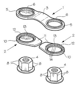
Figure 1 is an isometric view of a lug nut locking and indicator device in
accordance with the present invention;

Figure 2 is an exploded, isometric view of the lug nut locking and indicator
device of Fig. 1;

Figure 3 is a top view of a locking strip used in the device of Figs 1 and 2;
Figure 4 is a side view of the locking strip of Fig. 3;

Figure 5 is a top view of an indicator flag used in the device of Figs. 1 and
2;
and

Figure 6 is a front view of a vehicle wheel with a plurality of indicator and
locking devices mounted thereon.

DETAILED DESCRIPTION OF THE INVENTION

With reference to Figs. 1 and 2, the basic elements of the lug nut locking and
indicator device of the present invention include a locking strip indicated
generally
at 1 and an indicator flag indicated generally at 2.

As best shown in Figs. 2 - 4, the locking strip 1 includes a rigid, slightly
arched body 3 formed of hard plastic for extending between adjacent lug nuts
4. A
ring 5 is provided at each end of the body 3. The ring 5 is integral with the
body 3
and is defined by a hole through the circular ends of the body and an annular

flange 6 extending upwardly from the body around the hole. A circular row of
teeth
7 extends around the entire inner circumference of the ring 5 for engaging the
corners 8 of the lug nut 4.

3


CA 02734659 2011-03-22

Referring to Figs. 1 and 5, each indicator flag 2 is defined by an annular
body 10 with a short, tapering arm 11 integral with an extending outwardly
from one
side thereof. The top or outer surface of the arm 11 is preferably colored
with a
bright, highly noticeable color such as red. An annular flange 12 extends
upwardly

from around a hole 13 through the body 10. A row of teeth 14 extends
completely
around the periphery of the hole 13 for engaging the corners of the lug nut 4.

As illustrated in Fig. 6, the indicator device is used on adjacent lug nuts 4
securing a wheel 16 on a vehicle (not shown). The lug nuts 4 are mounted on
bolts
17. In use, a pair of indicator flags 2 is mounted first on adjacent, already
tightened

lug nuts 4 with the arms 11 pointing towards each other. The teeth 14 in the
hole
13 lock the flag 12 on the nut 4, i.e. prevent rotation of the flag relative
to the nut 4.
The locking strip 1 is then mounted on the adjacent lug nuts 4 above the
indicator
flags 2, so that the arms 11 of the flags are covered by the body 3 of the
strip (Fig.
6). Because the body 3 of the locking strip is rigid, and the teeth 7 engage
the

corners 8 of the lug nuts 4 rotation of the lug nuts is strongly resisted. If,
however,
the force of the rotation on one of the lug nuts 4 is sufficient to break the
teeth 7 in
one of the rings 5, the indicator flag 2 will rotate with the lug nut to a
position at an
angle or perpendicular to the longitudinal axis of the strip body 3 (e.g. to
the

position shown in phantom between the eight and nine o'clock positions of the

wheel 16). In this position, the flag 2 is no longer aligned with the
longitudinal axis
of the locking strip 1 and thus provides a visual indicator that the locking
nut 4 is
loosening. The flange 10 on the flag 2, and the bowed or arched body 3 reduce

4


CA 02734659 2011-03-22

contact between the strip 1 and the flag 2 to facilitate free rotation of the
flag 2
relative to the strip 1.

In the event that the wheel 16 is to be removed from the vehicle, it is merely
necessary to remove the locking strip 1 and the indicator flags 2. The
internal

diameter of the rings 5 on the ends of the strip 1 and the diameter of the
holes 13 in
the flags 2 are such that the strip 1 and the flags 2 are held in position on
the nuts 4
by friction, but can be pried off with a screwdriver or other tool.

Thus, there has been described a relatively simple lug nut locking and
indicator device, which strongly resists rotation of a pair of adjacent lug
nuts.

However, if rotation i.e. loosening of one of the lug nuts should occur, the
device
provides a visual indication of the event.

5

Dessin représentatif
Une figure unique qui représente un dessin illustrant l'invention.
États administratifs

Pour une meilleure compréhension de l'état de la demande ou brevet qui figure sur cette page, la rubrique Mise en garde , et les descriptions de Brevet , États administratifs , Taxes périodiques et Historique des paiements devraient être consultées.

États administratifs

Titre Date
Date de délivrance prévu 2018-05-01
(22) Dépôt 2011-03-22
(41) Mise à la disponibilité du public 2012-09-22
Requête d'examen 2016-03-21
(45) Délivré 2018-05-01

Historique d'abandonnement

Date d'abandonnement Raison Reinstatement Date
2013-03-22 Taxe périodique sur la demande impayée 2013-09-19

Taxes périodiques

Dernier paiement au montant de 125,00 $ a été reçu le 2024-03-19


 Montants des taxes pour le maintien en état à venir

Description Date Montant
Prochain paiement si taxe générale 2025-03-24 347,00 $
Prochain paiement si taxe applicable aux petites entités 2025-03-24 125,00 $

Avis : Si le paiement en totalité n'a pas été reçu au plus tard à la date indiquée, une taxe supplémentaire peut être imposée, soit une des taxes suivantes :

  • taxe de rétablissement ;
  • taxe pour paiement en souffrance ; ou
  • taxe additionnelle pour le renversement d'une péremption réputée.

Les taxes sur les brevets sont ajustées au 1er janvier de chaque année. Les montants ci-dessus sont les montants actuels s'ils sont reçus au plus tard le 31 décembre de l'année en cours.
Veuillez vous référer à la page web des taxes sur les brevets de l'OPIC pour voir tous les montants actuels des taxes.

Historique des paiements

Type de taxes Anniversaire Échéance Montant payé Date payée
Le dépôt d'une demande de brevet 200,00 $ 2011-03-22
Rétablissement: taxe de maintien en état non-payées pour la demande 200,00 $ 2013-09-19
Taxe de maintien en état - Demande - nouvelle loi 2 2013-03-22 50,00 $ 2013-09-19
Taxe de maintien en état - Demande - nouvelle loi 3 2014-03-24 50,00 $ 2014-03-21
Taxe de maintien en état - Demande - nouvelle loi 4 2015-03-23 50,00 $ 2015-03-19
Requête d'examen 400,00 $ 2016-03-21
Taxe de maintien en état - Demande - nouvelle loi 5 2016-03-22 100,00 $ 2016-03-21
Enregistrement de documents 100,00 $ 2016-04-12
Taxe de maintien en état - Demande - nouvelle loi 6 2017-03-22 100,00 $ 2017-03-22
Taxe finale 150,00 $ 2018-03-14
Taxe de maintien en état - Demande - nouvelle loi 7 2018-03-22 100,00 $ 2018-03-14
Taxe de maintien en état - brevet - nouvelle loi 8 2019-03-22 100,00 $ 2019-03-21
Taxe de maintien en état - brevet - nouvelle loi 9 2020-03-23 100,00 $ 2020-04-01
Taxe de maintien en état - brevet - nouvelle loi 10 2021-03-22 125,00 $ 2021-03-18
Taxe de maintien en état - brevet - nouvelle loi 11 2022-03-22 125,00 $ 2022-03-22
Taxe de maintien en état - brevet - nouvelle loi 12 2023-03-22 125,00 $ 2023-03-20
Taxe de maintien en état - brevet - nouvelle loi 13 2024-03-22 125,00 $ 2024-03-19
Titulaires au dossier

Les titulaires actuels et antérieures au dossier sont affichés en ordre alphabétique.

Titulaires actuels au dossier
PRINCE, LENNY
Titulaires antérieures au dossier
CENTRABALANCE CANADA INC.
Les propriétaires antérieurs qui ne figurent pas dans la liste des « Propriétaires au dossier » apparaîtront dans d'autres documents au dossier.
Documents

Pour visionner les fichiers sélectionnés, entrer le code reCAPTCHA :


Pour visualiser une image, cliquer sur un lien dans la colonne description du document. Pour télécharger l'image (les images), cliquer l'une ou plusieurs cases à cocher dans la première colonne et ensuite cliquer sur le bouton "Télécharger sélection en format PDF (archive Zip)" ou le bouton "Télécharger sélection (en un fichier PDF fusionné)".

Liste des documents de brevet publiés et non publiés sur la BDBC .

Si vous avez des difficultés à accéder au contenu, veuillez communiquer avec le Centre de services à la clientèle au 1-866-997-1936, ou envoyer un courriel au Centre de service à la clientèle de l'OPIC.


Description du
Document 
Date
(yyyy-mm-dd) 
Nombre de pages   Taille de l'image (Ko) 
Abrégé 2011-03-22 1 14
Description 2011-03-22 5 157
Revendications 2011-03-22 2 38
Dessins 2011-03-22 2 58
Dessins représentatifs 2011-11-17 1 13
Page couverture 2012-09-25 1 39
Revendications 2016-04-13 2 36
Cession 2011-03-22 2 67
Correspondance 2011-04-08 2 66
Modification 2017-09-06 2 57
Revendications 2017-09-06 2 34
Paiement de taxe périodique 2018-03-14 1 33
Taxe finale 2018-03-14 1 25
Dessins représentatifs 2018-04-04 1 12
Page couverture 2018-04-04 2 41
Correspondance 2011-04-04 1 21
Cession 2011-05-04 3 108
Paiement de taxe périodique 2019-03-21 1 33
Requête d'examen 2016-03-21 1 27
Lettre du bureau 2019-09-20 1 34
Taxes 2013-09-19 1 33
Taxes 2016-03-21 1 33
Taxes 2014-03-21 1 33
Modification 2016-04-13 2 61
Paiement de taxe périodique 2017-03-22 1 33
Demande d'examen 2017-03-27 3 134