Language selection

Search

Patent 2759001 Summary

Third-party information liability

Some of the information on this Web page has been provided by external sources. The Government of Canada is not responsible for the accuracy, reliability or currency of the information supplied by external sources. Users wishing to rely upon this information should consult directly with the source of the information. Content provided by external sources is not subject to official languages, privacy and accessibility requirements.

Claims and Abstract availability

Any discrepancies in the text and image of the Claims and Abstract are due to differing posting times. Text of the Claims and Abstract are posted:

  • At the time the application is open to public inspection;
  • At the time of issue of the patent (grant).
(12) Patent: (11) CA 2759001
(54) English Title: A READILY ADJUSTABLE AND LOCKABLE PEDESTAL FOR AN ACCESS FLOOR ASSEMBLY
(54) French Title: SOCLE FACILEMENT REGLABLE ET VERROUILLABLE POUR ENSEMBLE FAUX-PLANCHER
Status: Granted
Bibliographic Data
(51) International Patent Classification (IPC):
  • E04F 15/024 (2006.01)
(72) Inventors :
  • ZLATAR, PETAR (Australia)
(73) Owners :
  • ZLATAR, PETAR (Australia)
(71) Applicants :
  • ZLATAR, PETAR (Australia)
(74) Agent: OYEN WIGGS GREEN & MUTALA LLP
(74) Associate agent:
(45) Issued: 2017-07-11
(86) PCT Filing Date: 2010-04-16
(87) Open to Public Inspection: 2010-10-21
Examination requested: 2015-04-13
Availability of licence: N/A
(25) Language of filing: English

Patent Cooperation Treaty (PCT): Yes
(86) PCT Filing Number: PCT/AU2010/000418
(87) International Publication Number: WO2010/118467
(85) National Entry: 2011-10-17

(30) Application Priority Data:
Application No. Country/Territory Date
2009901637 Australia 2009-04-17

Abstracts

English Abstract


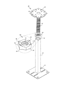
A pedestal (18) for an access floor assembly (10), the pedestal (18) comprises
a stand portion and a head portion.
The stand portion has a base plate (21) for resting upon a sub-floor (20), and
a stem (22) extending upwardly therefrom. The head
portion has a platform (24) and a threaded shaft (26) extending downwardly
therefrom. The pedestal (18) includes a lockable nut
(28) which has a thread (29) adapted to screwably engage the threaded shaft
(26), wherein the lockable nut (28) has at least one
detent (30) to lock with the stem (22) in order to prevent the rotation of the
lockable nut (28) when abutted against the stem (22).


French Abstract

La présente invention concerne un socle (18) pour ensemble faux-plancher (10), qui comprend une partie verticale et une partie tête. La partie verticale possède une plaque de base (21) destinée à reposer sur un sous-plancher (20) et une tige (22) qui s'élève verticalement depuis la plaque. La partie tête comporte une plateforme (24) et une tige filetée (26) qui s'étend de manière descendante depuis la plateforme. Le socle (18) possède un écrou verrouillable (28) présentant un filetage (29) conçu pour se visser à la tige filetée (26). L'écrou verrouillable (28) est doté d'au moins un cran (30) afin de lui permettre de se verrouiller à la tige (22) et prévenir ainsi la rotation de l'écrou verrouillable (28) lorsqu'il vient buter contre la tige (22).

Claims

Note: Claims are shown in the official language in which they were submitted.


7

CLAIMS:

1. A pedestal for an access floor assembly, the pedestal comprising:
a) a stand portion having
i. a base plate for resting upon a sub-floor, and
ii. a stem extending upwardly therefrom and having a square
profile so as to define four side surfaces of the stem,
b) a head portion having
i. a platform, and
ii. a threaded shaft extending downwardly therefrom, and
c) a lockable nut having a hexagon shape and which has a thread
adapted to screwably engage the threaded shaft, wherein the
lockable nut has four detents to lock with the stem in order to
prevent the rotation of the lockable nut along the threaded shaft
when abutted against the stem,
and wherein a first pair of the detents extend downwardly
from a respective first pair of adjacent corners which define
therebetween a first side surface of the lockable nut and a
second pair of the detents extend downwardly from a respective
second pair of adjacent corners which define therebetween a
second side surface of the lockable nut which is opposite the
first side surface of the lockable nut,
and wherein the four detents individually lock with the four
side surfaces of the stem by a first detent of the first pair of
detents abutting against a first side surface of the stem, a
second detent of the first pair of detents abutting against a
second side surface of the stem which is adjacent the first side
surface of the stem, a third detent of the second pair of detents
abutting against a third side surface of the stem which is


8

opposite the first side surface of the stem, and a fourth detent of
the second pair of detents abutting against a fourth side surface
of the stem which is opposite the second side surface of the
stem.
2. The pedestal of claim 1, wherein the platform of the head portion has
means for connecting the platform to different gaskets.
3. The pedestal of claim 2, wherein the platform is connectable with one or

more stringers which extend from the platform of the pedestal to another
pedestal.
4. An access floor assembly having a plurality of pedestals of claim 1
supporting a plurality of floor panels over a sub floor.
5. The access floor assembly of claim 4, wherein each of the platforms of
said pedestals has a means for engaging different gaskets.
6. The access floor assembly of claim 5, wherein at least one of the
pedestals is directly engageable with at least one stringer which extends
from the platform of said at least one of the pedestals to another of the
pedestals.

Description

Note: Descriptions are shown in the official language in which they were submitted.


CA 02759001 2016-08-31
1
A READILY ADJUSTABLE AND LOCKABLE PEDESTAL FOR AN ACCESS
FLOOR ASSEMBLY
TECHNICAL FIELD
The present invention relates to access flooring and, in particular, to a
readily adjustable and lockable pedestal for an access floor assembly.
BACKGROUND ART
Access flooring is a common feature of many computer, media and
communication rooms. Being raised above a sub-floor by pedestals, access
flooring provides underlying space to conceal and arrange cabling and other
service items used to operate the computers or other interactive equipment
located within the room. The interconnecting panels which define the surface
of
an access floor are designed to be readily taken up and rearranged, upon prior

removal of any overlying carpet or other floor coverings, when upgrading of
the
computers and other interactive equipment is required.
However, a problem with prior art pedestals used in access floor
assemblies is that height of the pedestals is not readily adjustable, making
installation a time consuming process. Another problem with prior art
pedestals
is that movement across an access floor panel may gradually rotate the head
portion of the pedestal and thereby raise or lower the level of the pedestal
and
the access floor panel supported by it. Yet another problem with prior art
pedestals is that they are relatively expensive because they comprise
numerous components which make manufacturing and assembling the
pedestals a relatively time consuming process.
It is, therefore, an object of the present invention to overcome, or at least
substantially ameliorate, the problems of prior art pedestals for access
floors.

CA 02759001 2016-08-31
2
DISCLOSURE OF INVENTION
According to the present invention there is provided a pedestal for an
access floor assembly, the pedestal comprising:
(a) a stand portion having
(i) a base plate for resting upon a sub-floor, and
(ii) a stem extending upwardly therefrom and having a square
profile
so as to define four side surfaces of the stem,
(b) a head portion having
(i) a platform, and
(ii) a threaded shaft extending downwardly therefrom, and
(c) a lockable nut having a hexagon shape and which has a thread adapted
to screwably engage the threaded shaft, wherein the lockable nut has
four detents to lock with the stem in order to prevent the rotation of the
lockable nut along the threaded shaft when abutted against the stem,
and wherein a first pair of the detents extend downwardly from a
respective first pair of adjacent corners which define therebetween a first
side surface of the lockable nut and a second pair of the detents extend
downwardly from a respective second pair of adjacent corners which
define therebetween a second side surface of the lockable nut which is
opposite the first side surface of the lockable nut,
and wherein the four detents individually lock with the four side
surfaces of the stem by a first detent of the first pair of detents abutting
against a first side surface of the stem, a second detent of the first pair
of detents abutting against a second side surface of the stem which is
adjacent the first side surface of the stem, a third detent of the second
pair of detents abutting against a third side surface of the stem which is
opposite the first side surface of the stem, and a fourth detent of the

CA 02759001 2016-08-31
3
second pair of detents abutting against a fourth side surface of the stem
which is opposite the second side surface of the stem.
In a preferred embodiment of the invention, the platform of the head
portion is adapted to engage a variety of gaskets and/or stringers.
Preferably, the platform is connectable with one or more stringers which
extend from one platform of the pedestal to another pedestal.
According to another aspect of the present invention, there is provided
an access floor assembly having a plurality of pedestals, as described above,
supporting a plurality of floor panels over a sub floor. Each pedestal
includes a
platform which may be adapted to engage different gaskets.
Preferably, the pedestal is directly engageable with at least one stringer
which extends from the platform of the pedestal to another pedestal.
BRIEF DESCRIPTION OF THE DRAWINGS
Fig. 1 is an exploded perspective view of an access floor assembly,
incorporating a plurality of pedestals according to one
embodiment of the present invention,
Fig. 2 is perspective view of one of the pedestals shown in Fig. 1,
Fig. 3 is an exploded perspective view of the pedestal shown in Fig. 2,
together with an enlarged view of the lockable nut,
Fig. 4 is a schematic top view of the square stem and hexagonal
lockable nut shown in Fig. 3,
Fig. 5 is a schematic top view of a square stem and square lockable nut,
Fig. 6 is a schematic top view of another square stem and octagonal
lockable nut,
Fig. 7 is a schematic top view of a triangular stem and triangular
lockable nut,

CA 02759001 2016-08-31
4
Fig. 8 is a schematic top view of a square stem and circular lockable
nut,
Fig. 9 is a schematic top view of a circular stem and circular lockable
nut,
Fig. 10 is a schematic top view of an irregularly shaped stem and
lockable nut,
Fig. 11 is a perspective view of a gasket for use with the pedestal of
Fig. 2,
Fig. 12 is a perspective view of another gasket for use with the pedestal
of Fig. 2,
Fig. 13 is a perspective view of another gasket for use with the pedestal
of Fig. 2,
Fig. 14 is a perspective view of another gasket for use with the pedestal
of Fig. 2, and
Fig. 15 is a perspective view of the platform of the pedestal of Fig. 2.
BEST MODE FOR CARRYING OUT THE INVENTION
The access floor assembly 10 shown in Fig. 1 includes an access floor
panel 12 which is supported by a plurality of stringers 14 which are connected

using fasteners 16 to a plurality of pedestals 18. The pedestals 18 raise the
access floor panel 12 above the sub-floor 20.
The pedestal 18 which is shown assembled in Fig. 2 and exploded in
Fig. 3 comprises a stand portion and a head portion. The stand portion
comprises a base plate 21 for resting upon the sub-floor 20, and a rectangular

shaped metal stem 22 extending upwardly therefrom.
The head portion has a platform 24 and a threaded metal shaft 26
extending downwardly therefrom. The pedestal 18 also comprises a lockable
nut 28 which has a threaded bore 29 adapted to engage the threaded metal

CA 02759001 2016-08-31
shaft 26. The lockable nut 28 has a hexagon shape with detents 30 adapted to
lock with stem 22 in order to prevent the rotation of the lockable nut 28
along
the threaded shaft 26 when the lockable nut 28 is abutted against the stem 22.

The height of the pedestal 18 may be adjusted by raising the threaded
5 shaft 26 out of the stem 22, adjusting the position of the lockable nut
28 along
the threaded shaft 26 and then lowering the lockable nut 28 over the stem 22
and inserting the threaded shaft 26 into the stem 22. The pedestal 18 is
therefore quickly and readily adjustable.
Various embodiments of the lockable nut 28 and the stem 22 are shown
in Figs. 4 to 10. In Fig. 4, the stem 22 (shown with broken lines) has a
square
profile and the lockable nut 28 (shown with unbroken lines) has a hexagonal
profile with four detents 30 (shown with hatched lines). In Fig. 5, the stem
22
has a square profile and the lockable nut 28 also has a square profile with
four
detents. In Fig. 6, the stem 22 has a square profile and the lockable nut 28
has
an octagonal profile with eight detents. In Fig. 7, the stem 22 has a
triangular
profile and the lockable nut 28 also has a triangular profile with three
detents.
In Fig. 8, the stem 22 has a square profile and the lockable nut 28 has a
circular profile with one detent. In Fig. 9, the stem 22 has a circular
profile with
two spokes adapted to trap the detent 30 on the lockable nut 28 which also has
a circular profile. In Fig. 10, the stem 22 has an irregular sided profile
which
may be encompassed by a lockable nut 28 which is hollow and also has a
larger profile of the same shape which acts as a detent 30.
The pedestal 18 is sturdy and able to sustain a significant amount of
weight. It is preferred for use with access floors which support a great deal
of
weight and are infrequently used by pedestrians (who prefer a less rigid
floor),
such as computer rooms containing many server racks and cabinets. The
present invention has less working components than prior art pedestals and is

CA 02759001 2016-08-31
6
therefore quicker to manufacture and assemble and is thereby cheaper to
produce than prior art pedestals.
The platform 24 of the pedestal 18 (see Fig. 2) is adapted to be attached
to a variety of different gaskets, as shown in Figs. 11 to 14. These different
gaskets allow different configurations or types of access floor panels 12 to
be
utilised, thereby providing flexibility during the installation phase. The
flanges
32, 34, 36 and 38 at the corners of the platform 24 are tapered so as to fit
the
corners of the gaskets. The gaskets may be secured to the platform 24 via
fasteners 16 which are placed through holes 39 in the platform 24. The
platform
24 can also be secured to the stringers 14 along the longitudinal flanges 40,
42,
44 and 46, as shown in Fig. 1.
Various modifications may be made in details of design and construction
without departing from the scope and ambit of the invention.
INDUSTRIAL APPLICABILITY
The present invention has an industrial application in the construction
industry for commercial, industrial and office building environments which
require access floors for particular applications.

Representative Drawing
A single figure which represents the drawing illustrating the invention.
Administrative Status

For a clearer understanding of the status of the application/patent presented on this page, the site Disclaimer , as well as the definitions for Patent , Administrative Status , Maintenance Fee  and Payment History  should be consulted.

Administrative Status

Title Date
Forecasted Issue Date 2017-07-11
(86) PCT Filing Date 2010-04-16
(87) PCT Publication Date 2010-10-21
(85) National Entry 2011-10-17
Examination Requested 2015-04-13
(45) Issued 2017-07-11

Abandonment History

There is no abandonment history.

Maintenance Fee

Last Payment of $347.00 was received on 2024-03-18


 Upcoming maintenance fee amounts

Description Date Amount
Next Payment if standard fee 2025-04-16 $624.00
Next Payment if small entity fee 2025-04-16 $253.00

Note : If the full payment has not been received on or before the date indicated, a further fee may be required which may be one of the following

  • the reinstatement fee;
  • the late payment fee; or
  • additional fee to reverse deemed expiry.

Patent fees are adjusted on the 1st of January every year. The amounts above are the current amounts if received by December 31 of the current year.
Please refer to the CIPO Patent Fees web page to see all current fee amounts.

Payment History

Fee Type Anniversary Year Due Date Amount Paid Paid Date
Application Fee $400.00 2011-10-17
Maintenance Fee - Application - New Act 2 2012-04-16 $100.00 2012-03-28
Maintenance Fee - Application - New Act 3 2013-04-16 $100.00 2013-04-12
Maintenance Fee - Application - New Act 4 2014-04-16 $100.00 2014-04-02
Maintenance Fee - Application - New Act 5 2015-04-16 $200.00 2015-03-25
Request for Examination $800.00 2015-04-13
Maintenance Fee - Application - New Act 6 2016-04-18 $200.00 2016-03-21
Maintenance Fee - Application - New Act 7 2017-04-18 $200.00 2017-04-03
Final Fee $300.00 2017-05-30
Maintenance Fee - Patent - New Act 8 2018-04-16 $400.00 2019-04-01
Maintenance Fee - Patent - New Act 9 2019-04-16 $200.00 2019-04-01
Maintenance Fee - Patent - New Act 10 2020-04-16 $250.00 2020-04-14
Maintenance Fee - Patent - New Act 11 2021-04-16 $255.00 2021-04-12
Maintenance Fee - Patent - New Act 12 2022-04-19 $254.49 2022-03-21
Maintenance Fee - Patent - New Act 13 2023-04-17 $263.14 2023-04-03
Maintenance Fee - Patent - New Act 14 2024-04-16 $347.00 2024-03-18
Owners on Record

Note: Records showing the ownership history in alphabetical order.

Current Owners on Record
ZLATAR, PETAR
Past Owners on Record
None
Past Owners that do not appear in the "Owners on Record" listing will appear in other documentation within the application.
Documents

To view selected files, please enter reCAPTCHA code :


To view images, click a link in the Document Description column. To download the documents, select one or more checkboxes in the first column and then click the "Download Selected in PDF format (Zip Archive)" or the "Download Selected as Single PDF" button.

List of published and non-published patent-specific documents on the CPD .

If you have any difficulty accessing content, you can call the Client Service Centre at 1-866-997-1936 or send them an e-mail at CIPO Client Service Centre.


Document
Description 
Date
(yyyy-mm-dd) 
Number of pages   Size of Image (KB) 
Maintenance Fee Payment 2020-04-14 1 33
Abstract 2011-10-17 1 57
Claims 2011-10-17 2 46
Drawings 2011-10-17 4 113
Description 2011-10-17 6 228
Representative Drawing 2011-10-17 1 22
Cover Page 2011-12-22 2 45
Description 2016-08-31 6 206
Claims 2016-08-31 2 54
Drawings 2016-08-31 4 110
Final Fee 2017-05-30 1 28
Representative Drawing 2017-06-08 1 10
Cover Page 2017-06-08 1 43
Maintenance Fee Payment 2019-04-01 1 33
PCT 2011-10-17 12 504
Assignment 2011-10-17 8 148
Fees 2012-03-28 1 163
Fees 2014-04-02 1 33
Fees 2015-03-25 1 33
Prosecution-Amendment 2015-04-13 1 33
Fees 2016-03-21 1 33
Examiner Requisition 2016-05-13 4 269
Amendment 2016-08-31 24 778
Maintenance Fee Payment 2017-04-03 1 33