Sélection de la langue

Search

Sommaire du brevet 2759001 

Énoncé de désistement de responsabilité concernant l'information provenant de tiers

Une partie des informations de ce site Web a été fournie par des sources externes. Le gouvernement du Canada n'assume aucune responsabilité concernant la précision, l'actualité ou la fiabilité des informations fournies par les sources externes. Les utilisateurs qui désirent employer cette information devraient consulter directement la source des informations. Le contenu fourni par les sources externes n'est pas assujetti aux exigences sur les langues officielles, la protection des renseignements personnels et l'accessibilité.

Disponibilité de l'Abrégé et des Revendications

L'apparition de différences dans le texte et l'image des Revendications et de l'Abrégé dépend du moment auquel le document est publié. Les textes des Revendications et de l'Abrégé sont affichés :

  • lorsque la demande peut être examinée par le public;
  • lorsque le brevet est émis (délivrance).
(12) Brevet: (11) CA 2759001
(54) Titre français: SOCLE FACILEMENT REGLABLE ET VERROUILLABLE POUR ENSEMBLE FAUX-PLANCHER
(54) Titre anglais: A READILY ADJUSTABLE AND LOCKABLE PEDESTAL FOR AN ACCESS FLOOR ASSEMBLY
Statut: Octroyé
Données bibliographiques
(51) Classification internationale des brevets (CIB):
  • E04F 15/024 (2006.01)
(72) Inventeurs :
  • ZLATAR, PETAR (Australie)
(73) Titulaires :
  • ZLATAR, PETAR (Australie)
(71) Demandeurs :
  • ZLATAR, PETAR (Australie)
(74) Agent: OYEN WIGGS GREEN & MUTALA LLP
(74) Co-agent:
(45) Délivré: 2017-07-11
(86) Date de dépôt PCT: 2010-04-16
(87) Mise à la disponibilité du public: 2010-10-21
Requête d'examen: 2015-04-13
Licence disponible: S.O.
(25) Langue des documents déposés: Anglais

Traité de coopération en matière de brevets (PCT): Oui
(86) Numéro de la demande PCT: PCT/AU2010/000418
(87) Numéro de publication internationale PCT: WO2010/118467
(85) Entrée nationale: 2011-10-17

(30) Données de priorité de la demande:
Numéro de la demande Pays / territoire Date
2009901637 Australie 2009-04-17

Abrégés

Abrégé français

La présente invention concerne un socle (18) pour ensemble faux-plancher (10), qui comprend une partie verticale et une partie tête. La partie verticale possède une plaque de base (21) destinée à reposer sur un sous-plancher (20) et une tige (22) qui s'élève verticalement depuis la plaque. La partie tête comporte une plateforme (24) et une tige filetée (26) qui s'étend de manière descendante depuis la plateforme. Le socle (18) possède un écrou verrouillable (28) présentant un filetage (29) conçu pour se visser à la tige filetée (26). L'écrou verrouillable (28) est doté d'au moins un cran (30) afin de lui permettre de se verrouiller à la tige (22) et prévenir ainsi la rotation de l'écrou verrouillable (28) lorsqu'il vient buter contre la tige (22).


Abrégé anglais


A pedestal (18) for an access floor assembly (10), the pedestal (18) comprises
a stand portion and a head portion.
The stand portion has a base plate (21) for resting upon a sub-floor (20), and
a stem (22) extending upwardly therefrom. The head
portion has a platform (24) and a threaded shaft (26) extending downwardly
therefrom. The pedestal (18) includes a lockable nut
(28) which has a thread (29) adapted to screwably engage the threaded shaft
(26), wherein the lockable nut (28) has at least one
detent (30) to lock with the stem (22) in order to prevent the rotation of the
lockable nut (28) when abutted against the stem (22).

Revendications

Note : Les revendications sont présentées dans la langue officielle dans laquelle elles ont été soumises.


7

CLAIMS:

1. A pedestal for an access floor assembly, the pedestal comprising:
a) a stand portion having
i. a base plate for resting upon a sub-floor, and
ii. a stem extending upwardly therefrom and having a square
profile so as to define four side surfaces of the stem,
b) a head portion having
i. a platform, and
ii. a threaded shaft extending downwardly therefrom, and
c) a lockable nut having a hexagon shape and which has a thread
adapted to screwably engage the threaded shaft, wherein the
lockable nut has four detents to lock with the stem in order to
prevent the rotation of the lockable nut along the threaded shaft
when abutted against the stem,
and wherein a first pair of the detents extend downwardly
from a respective first pair of adjacent corners which define
therebetween a first side surface of the lockable nut and a
second pair of the detents extend downwardly from a respective
second pair of adjacent corners which define therebetween a
second side surface of the lockable nut which is opposite the
first side surface of the lockable nut,
and wherein the four detents individually lock with the four
side surfaces of the stem by a first detent of the first pair of
detents abutting against a first side surface of the stem, a
second detent of the first pair of detents abutting against a
second side surface of the stem which is adjacent the first side
surface of the stem, a third detent of the second pair of detents
abutting against a third side surface of the stem which is


8

opposite the first side surface of the stem, and a fourth detent of
the second pair of detents abutting against a fourth side surface
of the stem which is opposite the second side surface of the
stem.
2. The pedestal of claim 1, wherein the platform of the head portion has
means for connecting the platform to different gaskets.
3. The pedestal of claim 2, wherein the platform is connectable with one or

more stringers which extend from the platform of the pedestal to another
pedestal.
4. An access floor assembly having a plurality of pedestals of claim 1
supporting a plurality of floor panels over a sub floor.
5. The access floor assembly of claim 4, wherein each of the platforms of
said pedestals has a means for engaging different gaskets.
6. The access floor assembly of claim 5, wherein at least one of the
pedestals is directly engageable with at least one stringer which extends
from the platform of said at least one of the pedestals to another of the
pedestals.

Description

Note : Les descriptions sont présentées dans la langue officielle dans laquelle elles ont été soumises.

CA 02759001 2016-08-31
1
A READILY ADJUSTABLE AND LOCKABLE PEDESTAL FOR AN ACCESS
FLOOR ASSEMBLY
TECHNICAL FIELD
The present invention relates to access flooring and, in particular, to a
readily adjustable and lockable pedestal for an access floor assembly.
BACKGROUND ART
Access flooring is a common feature of many computer, media and
communication rooms. Being raised above a sub-floor by pedestals, access
flooring provides underlying space to conceal and arrange cabling and other
service items used to operate the computers or other interactive equipment
located within the room. The interconnecting panels which define the surface
of
an access floor are designed to be readily taken up and rearranged, upon prior

removal of any overlying carpet or other floor coverings, when upgrading of
the
computers and other interactive equipment is required.
However, a problem with prior art pedestals used in access floor
assemblies is that height of the pedestals is not readily adjustable, making
installation a time consuming process. Another problem with prior art
pedestals
is that movement across an access floor panel may gradually rotate the head
portion of the pedestal and thereby raise or lower the level of the pedestal
and
the access floor panel supported by it. Yet another problem with prior art
pedestals is that they are relatively expensive because they comprise
numerous components which make manufacturing and assembling the
pedestals a relatively time consuming process.
It is, therefore, an object of the present invention to overcome, or at least
substantially ameliorate, the problems of prior art pedestals for access
floors.

CA 02759001 2016-08-31
2
DISCLOSURE OF INVENTION
According to the present invention there is provided a pedestal for an
access floor assembly, the pedestal comprising:
(a) a stand portion having
(i) a base plate for resting upon a sub-floor, and
(ii) a stem extending upwardly therefrom and having a square
profile
so as to define four side surfaces of the stem,
(b) a head portion having
(i) a platform, and
(ii) a threaded shaft extending downwardly therefrom, and
(c) a lockable nut having a hexagon shape and which has a thread adapted
to screwably engage the threaded shaft, wherein the lockable nut has
four detents to lock with the stem in order to prevent the rotation of the
lockable nut along the threaded shaft when abutted against the stem,
and wherein a first pair of the detents extend downwardly from a
respective first pair of adjacent corners which define therebetween a first
side surface of the lockable nut and a second pair of the detents extend
downwardly from a respective second pair of adjacent corners which
define therebetween a second side surface of the lockable nut which is
opposite the first side surface of the lockable nut,
and wherein the four detents individually lock with the four side
surfaces of the stem by a first detent of the first pair of detents abutting
against a first side surface of the stem, a second detent of the first pair
of detents abutting against a second side surface of the stem which is
adjacent the first side surface of the stem, a third detent of the second
pair of detents abutting against a third side surface of the stem which is
opposite the first side surface of the stem, and a fourth detent of the

CA 02759001 2016-08-31
3
second pair of detents abutting against a fourth side surface of the stem
which is opposite the second side surface of the stem.
In a preferred embodiment of the invention, the platform of the head
portion is adapted to engage a variety of gaskets and/or stringers.
Preferably, the platform is connectable with one or more stringers which
extend from one platform of the pedestal to another pedestal.
According to another aspect of the present invention, there is provided
an access floor assembly having a plurality of pedestals, as described above,
supporting a plurality of floor panels over a sub floor. Each pedestal
includes a
platform which may be adapted to engage different gaskets.
Preferably, the pedestal is directly engageable with at least one stringer
which extends from the platform of the pedestal to another pedestal.
BRIEF DESCRIPTION OF THE DRAWINGS
Fig. 1 is an exploded perspective view of an access floor assembly,
incorporating a plurality of pedestals according to one
embodiment of the present invention,
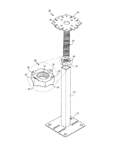
Fig. 2 is perspective view of one of the pedestals shown in Fig. 1,
Fig. 3 is an exploded perspective view of the pedestal shown in Fig. 2,
together with an enlarged view of the lockable nut,
Fig. 4 is a schematic top view of the square stem and hexagonal
lockable nut shown in Fig. 3,
Fig. 5 is a schematic top view of a square stem and square lockable nut,
Fig. 6 is a schematic top view of another square stem and octagonal
lockable nut,
Fig. 7 is a schematic top view of a triangular stem and triangular
lockable nut,

CA 02759001 2016-08-31
4
Fig. 8 is a schematic top view of a square stem and circular lockable
nut,
Fig. 9 is a schematic top view of a circular stem and circular lockable
nut,
Fig. 10 is a schematic top view of an irregularly shaped stem and
lockable nut,
Fig. 11 is a perspective view of a gasket for use with the pedestal of
Fig. 2,
Fig. 12 is a perspective view of another gasket for use with the pedestal
of Fig. 2,
Fig. 13 is a perspective view of another gasket for use with the pedestal
of Fig. 2,
Fig. 14 is a perspective view of another gasket for use with the pedestal
of Fig. 2, and
Fig. 15 is a perspective view of the platform of the pedestal of Fig. 2.
BEST MODE FOR CARRYING OUT THE INVENTION
The access floor assembly 10 shown in Fig. 1 includes an access floor
panel 12 which is supported by a plurality of stringers 14 which are connected

using fasteners 16 to a plurality of pedestals 18. The pedestals 18 raise the
access floor panel 12 above the sub-floor 20.
The pedestal 18 which is shown assembled in Fig. 2 and exploded in
Fig. 3 comprises a stand portion and a head portion. The stand portion
comprises a base plate 21 for resting upon the sub-floor 20, and a rectangular

shaped metal stem 22 extending upwardly therefrom.
The head portion has a platform 24 and a threaded metal shaft 26
extending downwardly therefrom. The pedestal 18 also comprises a lockable
nut 28 which has a threaded bore 29 adapted to engage the threaded metal

CA 02759001 2016-08-31
shaft 26. The lockable nut 28 has a hexagon shape with detents 30 adapted to
lock with stem 22 in order to prevent the rotation of the lockable nut 28
along
the threaded shaft 26 when the lockable nut 28 is abutted against the stem 22.

The height of the pedestal 18 may be adjusted by raising the threaded
5 shaft 26 out of the stem 22, adjusting the position of the lockable nut
28 along
the threaded shaft 26 and then lowering the lockable nut 28 over the stem 22
and inserting the threaded shaft 26 into the stem 22. The pedestal 18 is
therefore quickly and readily adjustable.
Various embodiments of the lockable nut 28 and the stem 22 are shown
in Figs. 4 to 10. In Fig. 4, the stem 22 (shown with broken lines) has a
square
profile and the lockable nut 28 (shown with unbroken lines) has a hexagonal
profile with four detents 30 (shown with hatched lines). In Fig. 5, the stem
22
has a square profile and the lockable nut 28 also has a square profile with
four
detents. In Fig. 6, the stem 22 has a square profile and the lockable nut 28
has
an octagonal profile with eight detents. In Fig. 7, the stem 22 has a
triangular
profile and the lockable nut 28 also has a triangular profile with three
detents.
In Fig. 8, the stem 22 has a square profile and the lockable nut 28 has a
circular profile with one detent. In Fig. 9, the stem 22 has a circular
profile with
two spokes adapted to trap the detent 30 on the lockable nut 28 which also has
a circular profile. In Fig. 10, the stem 22 has an irregular sided profile
which
may be encompassed by a lockable nut 28 which is hollow and also has a
larger profile of the same shape which acts as a detent 30.
The pedestal 18 is sturdy and able to sustain a significant amount of
weight. It is preferred for use with access floors which support a great deal
of
weight and are infrequently used by pedestrians (who prefer a less rigid
floor),
such as computer rooms containing many server racks and cabinets. The
present invention has less working components than prior art pedestals and is

CA 02759001 2016-08-31
6
therefore quicker to manufacture and assemble and is thereby cheaper to
produce than prior art pedestals.
The platform 24 of the pedestal 18 (see Fig. 2) is adapted to be attached
to a variety of different gaskets, as shown in Figs. 11 to 14. These different
gaskets allow different configurations or types of access floor panels 12 to
be
utilised, thereby providing flexibility during the installation phase. The
flanges
32, 34, 36 and 38 at the corners of the platform 24 are tapered so as to fit
the
corners of the gaskets. The gaskets may be secured to the platform 24 via
fasteners 16 which are placed through holes 39 in the platform 24. The
platform
24 can also be secured to the stringers 14 along the longitudinal flanges 40,
42,
44 and 46, as shown in Fig. 1.
Various modifications may be made in details of design and construction
without departing from the scope and ambit of the invention.
INDUSTRIAL APPLICABILITY
The present invention has an industrial application in the construction
industry for commercial, industrial and office building environments which
require access floors for particular applications.

Dessin représentatif
Une figure unique qui représente un dessin illustrant l'invention.
États administratifs

Pour une meilleure compréhension de l'état de la demande ou brevet qui figure sur cette page, la rubrique Mise en garde , et les descriptions de Brevet , États administratifs , Taxes périodiques et Historique des paiements devraient être consultées.

États administratifs

Titre Date
Date de délivrance prévu 2017-07-11
(86) Date de dépôt PCT 2010-04-16
(87) Date de publication PCT 2010-10-21
(85) Entrée nationale 2011-10-17
Requête d'examen 2015-04-13
(45) Délivré 2017-07-11

Historique d'abandonnement

Il n'y a pas d'historique d'abandonnement

Taxes périodiques

Dernier paiement au montant de 347,00 $ a été reçu le 2024-03-18


 Montants des taxes pour le maintien en état à venir

Description Date Montant
Prochain paiement si taxe générale 2025-04-16 624,00 $
Prochain paiement si taxe applicable aux petites entités 2025-04-16 253,00 $

Avis : Si le paiement en totalité n'a pas été reçu au plus tard à la date indiquée, une taxe supplémentaire peut être imposée, soit une des taxes suivantes :

  • taxe de rétablissement ;
  • taxe pour paiement en souffrance ; ou
  • taxe additionnelle pour le renversement d'une péremption réputée.

Les taxes sur les brevets sont ajustées au 1er janvier de chaque année. Les montants ci-dessus sont les montants actuels s'ils sont reçus au plus tard le 31 décembre de l'année en cours.
Veuillez vous référer à la page web des taxes sur les brevets de l'OPIC pour voir tous les montants actuels des taxes.

Historique des paiements

Type de taxes Anniversaire Échéance Montant payé Date payée
Le dépôt d'une demande de brevet 400,00 $ 2011-10-17
Taxe de maintien en état - Demande - nouvelle loi 2 2012-04-16 100,00 $ 2012-03-28
Taxe de maintien en état - Demande - nouvelle loi 3 2013-04-16 100,00 $ 2013-04-12
Taxe de maintien en état - Demande - nouvelle loi 4 2014-04-16 100,00 $ 2014-04-02
Taxe de maintien en état - Demande - nouvelle loi 5 2015-04-16 200,00 $ 2015-03-25
Requête d'examen 800,00 $ 2015-04-13
Taxe de maintien en état - Demande - nouvelle loi 6 2016-04-18 200,00 $ 2016-03-21
Taxe de maintien en état - Demande - nouvelle loi 7 2017-04-18 200,00 $ 2017-04-03
Taxe finale 300,00 $ 2017-05-30
Taxe de maintien en état - brevet - nouvelle loi 8 2018-04-16 400,00 $ 2019-04-01
Taxe de maintien en état - brevet - nouvelle loi 9 2019-04-16 200,00 $ 2019-04-01
Taxe de maintien en état - brevet - nouvelle loi 10 2020-04-16 250,00 $ 2020-04-14
Taxe de maintien en état - brevet - nouvelle loi 11 2021-04-16 255,00 $ 2021-04-12
Taxe de maintien en état - brevet - nouvelle loi 12 2022-04-19 254,49 $ 2022-03-21
Taxe de maintien en état - brevet - nouvelle loi 13 2023-04-17 263,14 $ 2023-04-03
Taxe de maintien en état - brevet - nouvelle loi 14 2024-04-16 347,00 $ 2024-03-18
Titulaires au dossier

Les titulaires actuels et antérieures au dossier sont affichés en ordre alphabétique.

Titulaires actuels au dossier
ZLATAR, PETAR
Titulaires antérieures au dossier
S.O.
Les propriétaires antérieurs qui ne figurent pas dans la liste des « Propriétaires au dossier » apparaîtront dans d'autres documents au dossier.
Documents

Pour visionner les fichiers sélectionnés, entrer le code reCAPTCHA :


Pour visualiser une image, cliquer sur un lien dans la colonne description du document. Pour télécharger l'image (les images), cliquer l'une ou plusieurs cases à cocher dans la première colonne et ensuite cliquer sur le bouton "Télécharger sélection en format PDF (archive Zip)" ou le bouton "Télécharger sélection (en un fichier PDF fusionné)".

Liste des documents de brevet publiés et non publiés sur la BDBC .

Si vous avez des difficultés à accéder au contenu, veuillez communiquer avec le Centre de services à la clientèle au 1-866-997-1936, ou envoyer un courriel au Centre de service à la clientèle de l'OPIC.


Description du
Document 
Date
(yyyy-mm-dd) 
Nombre de pages   Taille de l'image (Ko) 
Paiement de taxe périodique 2020-04-14 1 33
Abrégé 2011-10-17 1 57
Revendications 2011-10-17 2 46
Dessins 2011-10-17 4 113
Description 2011-10-17 6 228
Dessins représentatifs 2011-10-17 1 22
Page couverture 2011-12-22 2 45
Description 2016-08-31 6 206
Revendications 2016-08-31 2 54
Dessins 2016-08-31 4 110
Taxe finale 2017-05-30 1 28
Dessins représentatifs 2017-06-08 1 10
Page couverture 2017-06-08 1 43
Paiement de taxe périodique 2019-04-01 1 33
PCT 2011-10-17 12 504
Cession 2011-10-17 8 148
Taxes 2012-03-28 1 163
Taxes 2014-04-02 1 33
Taxes 2015-03-25 1 33
Poursuite-Amendment 2015-04-13 1 33
Taxes 2016-03-21 1 33
Demande d'examen 2016-05-13 4 269
Modification 2016-08-31 24 778
Paiement de taxe périodique 2017-04-03 1 33