Language selection

Search

Patent 2759002 Summary

Third-party information liability

Some of the information on this Web page has been provided by external sources. The Government of Canada is not responsible for the accuracy, reliability or currency of the information supplied by external sources. Users wishing to rely upon this information should consult directly with the source of the information. Content provided by external sources is not subject to official languages, privacy and accessibility requirements.

Claims and Abstract availability

Any discrepancies in the text and image of the Claims and Abstract are due to differing posting times. Text of the Claims and Abstract are posted:

  • At the time the application is open to public inspection;
  • At the time of issue of the patent (grant).
(12) Patent: (11) CA 2759002
(54) English Title: ARRANGEMENT FOR MOUNTING A SUPPORT BASE ON A WALL
(54) French Title: AGENCEMENT POUR MONTER UNE BASE DE SUPPORT SUR UN MUR
Status: Granted
Bibliographic Data
(51) International Patent Classification (IPC):
  • A61G 1/06 (2006.01)
  • A61G 3/00 (2006.01)
(72) Inventors :
  • VUORENOJA, ARI-MATTI (Finland)
(73) Owners :
  • FRESTEMS OY (Finland)
(71) Applicants :
  • FRESTEMS OY (Finland)
(74) Agent: BERESKIN & PARR LLP/S.E.N.C.R.L.,S.R.L.
(74) Associate agent:
(45) Issued: 2017-02-21
(86) PCT Filing Date: 2009-10-16
(87) Open to Public Inspection: 2010-04-22
Examination requested: 2014-10-15
Availability of licence: N/A
(25) Language of filing: English

Patent Cooperation Treaty (PCT): Yes
(86) PCT Filing Number: PCT/FI2009/000090
(87) International Publication Number: WO2010/043753
(85) National Entry: 2011-10-17

(30) Application Priority Data:
Application No. Country/Territory Date
20080580 Finland 2008-10-17

Abstracts

English Abstract


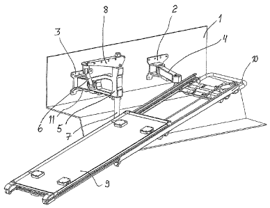
Arrangement for attaching a base (10), a tray, a platform or a similar support
to a wall with the help of timing
arms (4), (5) attached to the mentioned wall in which case the mentioned base
can be moved with the help of the arms (4), (5).
The base can be moved outwards from the wall in horizontal direction at the
first stage of the moving in which case the first arm
(4) and the second arm (5) of the arms are both hinged to be turning out of
the wall in horizontal direction and the mentioned base
(10) is attached to the moveable ends of the arms (4), (5) and that in the
arrangement when the moving of the base (10) sideways
is further continued, an elevation adjustment bar (7) belonging to the second
arm (5) and sliding in the height direction is arranged
to slide downwards and at the same time to set the support elements of the
base (10) lower at the location of the second arm (5) in
order to achieve a tilted position for the base (10).


French Abstract

Linvention concerne un agencement pour attacher une base (10), un plateau, une plateforme ou un support semblable à un mur à laide de bras pivotants (4), (5) attachés au mur mentionné, la base mentionnée pouvant être déplacée à laide des bras (4), (5). Lors de la première étape du déplacement, la base peut être éloignée du mur en direction horizontale, le premier bras (4) et le second bras (5) des bras étant tous les deux à charnière pour pivoter à partir du mur en direction horizontale et la base mentionnée (10) étant attachée aux extrémités mobiles des bras (4), (5). Lorsque le déplacement de la base (10) sur le côté est poursuivi, une barre dajustement de lélévation (7), qui fait partie du second bras (5) et qui coulisse dans la direction de la hauteur, est prévue dans lagencement pour glisser vers le bas et en même temps pour placer les éléments de support de la base (10) plus bas à lemplacement du second bras (5) afin dobtenir une position inclinée pour la base (10).

Claims

Note: Claims are shown in the official language in which they were submitted.

5
CLAIMS
1. Arrangement for attaching a stretcher base (10), a tray, a platform or a
similar
support to a wall with two turning arms (4), (5) each of the arms being
attached to the
mentioned wall with their own attachment fixtures (2), (3) in which case the
mentioned
stretcher base can be moved with the arms (4), (5), characterized in that the
stretcher
base can be moved outwards from the wall in a horizontal direction at a first
stage of
the moving in which case a first arm (4) and a second arm (5) of the arms are
both
hinged to be turning out of the wall in a horizontal direction and the
mentioned
stretcher base (10) is attached to the moveable ends of the arms (4), (5) and
that in the
arrangement when the moving of the stretcher base (10) sideways is further
continued,
an elevation adjustment bar (7) belonging to the second arm (5) and sliding in
a height
direction is arranged to slide downwards and at the same time to set the
support
elements of the stretcher base (10) lower at the location of the second arm
(5) in order
to achieve a tilted position for the stretcher base (10).
2. Arrangement according to the claim 1, characterized in that by the
elevation
adjustment bar (7) there is a gas spring or an alleviation spring lifting the
elevation
adjustment bar (7) upwards.
3. Arrangement according to the claim 1, characterized in that by the second
arm (5)
there is a force control element (6) that controls the lowering of the
elevation
adjustment bar (7) when the arm (5) turns.
4. Arrangement according to the claim 1, characterized in that a force control
element
(6) is attached with a hinge attachment at the force control element (6) ends
both to the
second arm (5) and to the elevation adjustment bar (7) or to an extension arm
(8) of
the force control element (6).
5. Arrangement according to the claim 1, characterized in that a convex track
or a line
that comes downwards functions as a force control element which track or a
line one
part of the elevation adjustment bar (7) is attached to follow when the
elevation

6
adjustment bar (7) turns.
6. Arrangement according to the claim 1, characterized in that the first (4)
and the
second arm (5) are organised in relation to their length and the locations of
the hinge
attachments to the wall (1) thereby that the stretcher base (10) has the same
direction
as the wall essentially in the nearest position and has the same direction as
the wall
also in one position being pulled out of the wall.
7. Arrangement according to the claim 1, characterized in that the first (4)
and the
second arms (5) are arranged in relation to the wall (1) regarding their
lengths and the
locations of the hinge attachments thereby that the stretcher base (10)
deviates from the
direction of the wall when the stretcher base (10) is in the tilted position.
8. Arrangement according to the claim 1, characterized in that the turning of
the arms
(4), (5) can be locked to extreme positions and at least to one mid position.

Description

Note: Descriptions are shown in the official language in which they were submitted.


CA 02759002 2011-10-17
WO 2010/043753 PCT/F12009/000090
1
ARRANGEMENT FOR MOUNTING A SUPPORT BASE ON A WALL

The invention relates to an arrangement in order to attach a base, a tray, a
platform or a
similar support on a wall with the help of turning arms that are attached to
the above
mentioned wall in which case the above mentioned base can be moved with the
help of the
arms.

Previously it is known mechanisms which can be attached to a wall according to
the above
mentioned preamble wherein by means of which mechanisms said bases or trays
that are
located next to the wall have been moved further away from the wall and
possibly have
been locked to this position by locking the hinges or the arms with a known
method to a
certain turning angle. This kind of solutions are known for example in the
ambulance
vehicles in which case a stretcher supported by the base are organised next to
the wall and
correspondingly away from the wall farther out for a nursing action. In these
cases the
moving of the patient on the stretcher onto the base located in the vehicle
and
correspondingly away from the base and out is a difficult procedure in which
at least two
persons, who can still lift relatively large loads, are needed.

In the publication DE 1161386 B a base that is attached to the wall with the
help of
turning arms is shown. The base can be moved away from the wall by turning the
arms.
One of the arms has been hinged to be turning around the vertical axis in
which case the
head of the arm maintains its altitude during the turning movement. Another
arm is hinged
to be turning around deviating from the vertical direction in which case the
head of its arm
begins to move to a lower position when the turning angle of the arm is
increased. The
base attached to the arm of this head also immediately starts to move down at
the same
time the consequence of which is the fact that the base tilts the more, the
more the arms
are turned away from the wall. With this arrangement it is not possible to
achieve such a
nursing position of the patient on the base where the base would have been
pulled away
from the wall and where the base would still have a landscape orientation.

In order to solve the above mentioned problem a new arrangement has been
developed in
order to attach the base to the wall in which case for example a patient lying
on the
stretcher is easy to move supported by the base and away from it or
correspondingly

CQNFIRMATION COPY


CA 02759002 2011-10-17
WO 2010/043753 PCT/F12009/000090
2
loadings occuring on this kind of base are easy to perform in other
applications. A
significant advantage is the fact that the patient lying on the base can be
treated on both
sides of the base because with the help of the arrangement it is possible to
draw the base
off the wall when it still has the landscape orientation and lock the base to
be immovable
at that location.

For the arrangement according to the invention in which arrangement a base, a
tray, a
platform or a similar support can be moved to essentially most advantageous
positions it is
characteristic for the loading that the base can be moved from the wall in
horizontal
direction outwards at the first stage of the moving in which case both the
first arm of the
arms and the second arm have been hinged to turn in horizontal plane out of
the wall and
the mentioned base is attached to the moveable ends of the arms and that when
in the
arrangement one further continues to move the base sideways, an elevation
adjustment bar
belonging to the second arm and sliding in height direction is arranged to
slide downwards
and at the same time to set the support elements of the base lower at the
location of the
second arm in order to the create a slanted position for the base.

The advantage of the invention is the fact that the base that can be moved
next to the wall
is easy to move with the load or without it and also easy to move from the
wall and to
make come down to a better loading position and also in the vehicle cases
partly also out
of the door in such a way that the loading supported by the base becomes
considerably
easier. The base can be locked to various locations - if needed - for example
a little bit
from the wall to an out pulled position in which case the base still has the
same direction
as the wall.

In the following the invention is described more detailed by referring to the
accompanying
drawing in which
Figure 1 shows a stretcher base that can be attached to the wall of the
vehicle
which base has the position that is nearest to the wall.
Figure 2 shows the stretcher base of the figure 1 being moved a little bit
from the
wall.
Figure 3 shows the stretcher base of the figure 1 being moved from the wall to
a
nursing position.


CA 02759002 2011-10-17
WO 2010/043753 PCT/F12009/000090
3
Figure 4 shows the stretcher base of the figure 1 in the loading position.

In the figure 1 there is a stretcher base 9, 10 that is attached to the wall 1
of the vehicle
with the help of attachment fixtures 2 and 3 which stretcher base is adjusted
to be
moveable with the help of the first arm 4 and the second arm 5 that turn
supported by the
hinges. The arms 4 and 5 are being turned next to the wall 1 in which case the
base 9, 10
is next to the wall.

In the figure 2 the arms 4 and 5 are a little bit turned away out of the wall
in which case
also the base 9, 10 has moved a little bit from the wall. The base has moved
in horizontal
direction out of the wall.

In the figure 3 the base 9, 10 has moved so much out of the wall 1 in
horizontal direction
that it has reached a position in relation to the lengths of the first arm 4
and the second arm
5 and also regarding the distances of the pivots of their arms from the wall 1
in which
position it has the direction of the wall and has essentially the same height
as it had next to
the wall when it was at the start situation.

In this position the locking of the base to this position belongs to this
arrangement which
locking is realised with the help of the sector plate 11 attached to the
attachment element 3
and with the help of a interlocking bolt 12 that is protruded to its hole in
this position. This
position is an advantageous nursing position of a patient when such thing is
performed in
the vehicle.
In the figure 4 there is a situation where the base 9, 10 has been moved for
example by
pulling from the base and by pressing a little bit to the loading position.
The arrangement
according to the invention tilts the base 9, 10 when it is further transferred
from the
situation of the figure 3 in such a way that the turning movement of the arms
4 and 5
increases. A vertical elevation adjustment bar 7 that is mounted in bearings
to be sliding at
the end of the arm 5 belongs to the second arm 5 to the lower end of which
elevation
adjustment bar a horizontal balk that supports the base 9, 10 is adjusted.
When the
turning movement of the arms 4, 5 increases from the position of the figure 3
the elevation
adjustment bar 7 begins to move down lower at the end of the arm 5 due to the
fact that


CA 02759002 2011-10-17
WO 2010/043753 PCT/F12009/000090
4
another bar 6 is attached to the extension arm 8 attached to the upper end of
the mentioned
bar 7 the upper part of which bar is attached to the extension arm 8 with the
help of a
hinge and the lower part is attached to the arm 5 with the help of a hinge. In
the position of
the figure 3 the bar 6 is positioned nearly vertically in which case the
elevation adjustment
bar 7 is essentially in the upper position. When the arms 4 and 5 according to
the figure 4
are more turned and the base 9, 10 maintains its direction due to the choice
of lengths of
the arms 4, 5 the bar 6 is turned to a diagonal position and has pulled at the
same time the
elevation adjustment bar 7 to a lower position by force. Due to this the base
9, 10 is tilted
to an advantageous loading position.

A movable carriage 9 that is on top belongs knowingly to the stretcher base 10
that helps
during the loading process of the patient stretcher in which case the loading
can be
performed outside the vehicle. The moving of the base 9, 10 with the load to
the vehicle
becomes easier when a gas spring is installed with the elevation adjustment
bar 7 in order
to lighten the lifting of the base.

Also with the choosing of the lengths of the arms 4 and 5 one can have an
impact on the
fact that in the position of the figure 4 the base has a suitable direction
for example in
relation to the door of the vehicle or in relation of other constructions.

The arrangement is suitable for any kind of loading and moving of a platform,
a tray or
similar table with the load or without it from an advantageous, tilted
position up in
horizontal direction and further to be able to do even side movements.
30

Representative Drawing
A single figure which represents the drawing illustrating the invention.
Administrative Status

For a clearer understanding of the status of the application/patent presented on this page, the site Disclaimer , as well as the definitions for Patent , Administrative Status , Maintenance Fee  and Payment History  should be consulted.

Administrative Status

Title Date
Forecasted Issue Date 2017-02-21
(86) PCT Filing Date 2009-10-16
(87) PCT Publication Date 2010-04-22
(85) National Entry 2011-10-17
Examination Requested 2014-10-15
(45) Issued 2017-02-21

Abandonment History

There is no abandonment history.

Maintenance Fee

Last Payment of $263.14 was received on 2023-09-27


 Upcoming maintenance fee amounts

Description Date Amount
Next Payment if small entity fee 2024-10-16 $253.00
Next Payment if standard fee 2024-10-16 $624.00

Note : If the full payment has not been received on or before the date indicated, a further fee may be required which may be one of the following

  • the reinstatement fee;
  • the late payment fee; or
  • additional fee to reverse deemed expiry.

Patent fees are adjusted on the 1st of January every year. The amounts above are the current amounts if received by December 31 of the current year.
Please refer to the CIPO Patent Fees web page to see all current fee amounts.

Payment History

Fee Type Anniversary Year Due Date Amount Paid Paid Date
Reinstatement of rights $200.00 2011-10-17
Application Fee $400.00 2011-10-17
Maintenance Fee - Application - New Act 2 2011-10-17 $100.00 2011-10-17
Maintenance Fee - Application - New Act 3 2012-10-16 $100.00 2012-10-15
Maintenance Fee - Application - New Act 4 2013-10-16 $100.00 2013-10-10
Request for Examination $800.00 2014-10-15
Maintenance Fee - Application - New Act 5 2014-10-16 $200.00 2014-10-15
Maintenance Fee - Application - New Act 6 2015-10-16 $200.00 2015-10-08
Maintenance Fee - Application - New Act 7 2016-10-17 $200.00 2016-09-16
Final Fee $300.00 2017-01-05
Maintenance Fee - Patent - New Act 8 2017-10-16 $200.00 2017-10-10
Maintenance Fee - Patent - New Act 9 2018-10-16 $200.00 2018-10-09
Maintenance Fee - Patent - New Act 10 2019-10-16 $250.00 2019-10-04
Maintenance Fee - Patent - New Act 11 2020-10-16 $255.00 2021-03-12
Late Fee for failure to pay new-style Patent Maintenance Fee 2021-03-12 $150.00 2021-03-12
Maintenance Fee - Patent - New Act 12 2021-10-18 $255.00 2021-09-04
Maintenance Fee - Patent - New Act 13 2022-10-17 $254.49 2022-09-17
Maintenance Fee - Patent - New Act 14 2023-10-16 $263.14 2023-09-27
Owners on Record

Note: Records showing the ownership history in alphabetical order.

Current Owners on Record
FRESTEMS OY
Past Owners on Record
None
Past Owners that do not appear in the "Owners on Record" listing will appear in other documentation within the application.
Documents

To view selected files, please enter reCAPTCHA code :


To view images, click a link in the Document Description column. To download the documents, select one or more checkboxes in the first column and then click the "Download Selected in PDF format (Zip Archive)" or the "Download Selected as Single PDF" button.

List of published and non-published patent-specific documents on the CPD .

If you have any difficulty accessing content, you can call the Client Service Centre at 1-866-997-1936 or send them an e-mail at CIPO Client Service Centre.


Document
Description 
Date
(yyyy-mm-dd) 
Number of pages   Size of Image (KB) 
Maintenance Fee Payment 2021-09-04 1 28
Office Letter 2021-11-30 1 185
Letter of Remission 2021-12-21 2 190
Maintenance Fee Payment 2022-09-17 1 25
Abstract 2011-10-17 1 74
Claims 2011-10-17 2 64
Drawings 2011-10-17 2 123
Description 2011-10-17 4 194
Representative Drawing 2011-12-22 1 28
Cover Page 2011-12-22 2 67
Claims 2016-02-10 2 63
Representative Drawing 2017-01-18 1 24
Cover Page 2017-01-18 2 66
PCT 2011-10-17 10 272
Assignment 2011-10-17 5 115
Examiner Requisition 2015-08-11 5 245
Prosecution-Amendment 2014-10-15 1 44
Amendment 2016-02-10 8 314
Fees 2016-09-16 1 33
Final Fee 2017-01-05 1 42
Maintenance Fee Payment 2023-09-27 1 27