Sélection de la langue

Search

Sommaire du brevet 2759002 

Énoncé de désistement de responsabilité concernant l'information provenant de tiers

Une partie des informations de ce site Web a été fournie par des sources externes. Le gouvernement du Canada n'assume aucune responsabilité concernant la précision, l'actualité ou la fiabilité des informations fournies par les sources externes. Les utilisateurs qui désirent employer cette information devraient consulter directement la source des informations. Le contenu fourni par les sources externes n'est pas assujetti aux exigences sur les langues officielles, la protection des renseignements personnels et l'accessibilité.

Disponibilité de l'Abrégé et des Revendications

L'apparition de différences dans le texte et l'image des Revendications et de l'Abrégé dépend du moment auquel le document est publié. Les textes des Revendications et de l'Abrégé sont affichés :

  • lorsque la demande peut être examinée par le public;
  • lorsque le brevet est émis (délivrance).
(12) Brevet: (11) CA 2759002
(54) Titre français: AGENCEMENT POUR MONTER UNE BASE DE SUPPORT SUR UN MUR
(54) Titre anglais: ARRANGEMENT FOR MOUNTING A SUPPORT BASE ON A WALL
Statut: Octroyé
Données bibliographiques
(51) Classification internationale des brevets (CIB):
  • A61G 1/06 (2006.01)
  • A61G 3/00 (2006.01)
(72) Inventeurs :
  • VUORENOJA, ARI-MATTI (Finlande)
(73) Titulaires :
  • FRESTEMS OY (Finlande)
(71) Demandeurs :
  • FRESTEMS OY (Finlande)
(74) Agent: BERESKIN & PARR LLP/S.E.N.C.R.L.,S.R.L.
(74) Co-agent:
(45) Délivré: 2017-02-21
(86) Date de dépôt PCT: 2009-10-16
(87) Mise à la disponibilité du public: 2010-04-22
Requête d'examen: 2014-10-15
Licence disponible: S.O.
(25) Langue des documents déposés: Anglais

Traité de coopération en matière de brevets (PCT): Oui
(86) Numéro de la demande PCT: PCT/FI2009/000090
(87) Numéro de publication internationale PCT: WO2010/043753
(85) Entrée nationale: 2011-10-17

(30) Données de priorité de la demande:
Numéro de la demande Pays / territoire Date
20080580 Finlande 2008-10-17

Abrégés

Abrégé français

Linvention concerne un agencement pour attacher une base (10), un plateau, une plateforme ou un support semblable à un mur à laide de bras pivotants (4), (5) attachés au mur mentionné, la base mentionnée pouvant être déplacée à laide des bras (4), (5). Lors de la première étape du déplacement, la base peut être éloignée du mur en direction horizontale, le premier bras (4) et le second bras (5) des bras étant tous les deux à charnière pour pivoter à partir du mur en direction horizontale et la base mentionnée (10) étant attachée aux extrémités mobiles des bras (4), (5). Lorsque le déplacement de la base (10) sur le côté est poursuivi, une barre dajustement de lélévation (7), qui fait partie du second bras (5) et qui coulisse dans la direction de la hauteur, est prévue dans lagencement pour glisser vers le bas et en même temps pour placer les éléments de support de la base (10) plus bas à lemplacement du second bras (5) afin dobtenir une position inclinée pour la base (10).


Abrégé anglais


Arrangement for attaching a base (10), a tray, a platform or a similar support
to a wall with the help of timing
arms (4), (5) attached to the mentioned wall in which case the mentioned base
can be moved with the help of the arms (4), (5).
The base can be moved outwards from the wall in horizontal direction at the
first stage of the moving in which case the first arm
(4) and the second arm (5) of the arms are both hinged to be turning out of
the wall in horizontal direction and the mentioned base
(10) is attached to the moveable ends of the arms (4), (5) and that in the
arrangement when the moving of the base (10) sideways
is further continued, an elevation adjustment bar (7) belonging to the second
arm (5) and sliding in the height direction is arranged
to slide downwards and at the same time to set the support elements of the
base (10) lower at the location of the second arm (5) in
order to achieve a tilted position for the base (10).

Revendications

Note : Les revendications sont présentées dans la langue officielle dans laquelle elles ont été soumises.


5
CLAIMS
1. Arrangement for attaching a stretcher base (10), a tray, a platform or a
similar
support to a wall with two turning arms (4), (5) each of the arms being
attached to the
mentioned wall with their own attachment fixtures (2), (3) in which case the
mentioned
stretcher base can be moved with the arms (4), (5), characterized in that the
stretcher
base can be moved outwards from the wall in a horizontal direction at a first
stage of
the moving in which case a first arm (4) and a second arm (5) of the arms are
both
hinged to be turning out of the wall in a horizontal direction and the
mentioned
stretcher base (10) is attached to the moveable ends of the arms (4), (5) and
that in the
arrangement when the moving of the stretcher base (10) sideways is further
continued,
an elevation adjustment bar (7) belonging to the second arm (5) and sliding in
a height
direction is arranged to slide downwards and at the same time to set the
support
elements of the stretcher base (10) lower at the location of the second arm
(5) in order
to achieve a tilted position for the stretcher base (10).
2. Arrangement according to the claim 1, characterized in that by the
elevation
adjustment bar (7) there is a gas spring or an alleviation spring lifting the
elevation
adjustment bar (7) upwards.
3. Arrangement according to the claim 1, characterized in that by the second
arm (5)
there is a force control element (6) that controls the lowering of the
elevation
adjustment bar (7) when the arm (5) turns.
4. Arrangement according to the claim 1, characterized in that a force control
element
(6) is attached with a hinge attachment at the force control element (6) ends
both to the
second arm (5) and to the elevation adjustment bar (7) or to an extension arm
(8) of
the force control element (6).
5. Arrangement according to the claim 1, characterized in that a convex track
or a line
that comes downwards functions as a force control element which track or a
line one
part of the elevation adjustment bar (7) is attached to follow when the
elevation

6
adjustment bar (7) turns.
6. Arrangement according to the claim 1, characterized in that the first (4)
and the
second arm (5) are organised in relation to their length and the locations of
the hinge
attachments to the wall (1) thereby that the stretcher base (10) has the same
direction
as the wall essentially in the nearest position and has the same direction as
the wall
also in one position being pulled out of the wall.
7. Arrangement according to the claim 1, characterized in that the first (4)
and the
second arms (5) are arranged in relation to the wall (1) regarding their
lengths and the
locations of the hinge attachments thereby that the stretcher base (10)
deviates from the
direction of the wall when the stretcher base (10) is in the tilted position.
8. Arrangement according to the claim 1, characterized in that the turning of
the arms
(4), (5) can be locked to extreme positions and at least to one mid position.

Description

Note : Les descriptions sont présentées dans la langue officielle dans laquelle elles ont été soumises.


CA 02759002 2011-10-17
WO 2010/043753 PCT/F12009/000090
1
ARRANGEMENT FOR MOUNTING A SUPPORT BASE ON A WALL

The invention relates to an arrangement in order to attach a base, a tray, a
platform or a
similar support on a wall with the help of turning arms that are attached to
the above
mentioned wall in which case the above mentioned base can be moved with the
help of the
arms.

Previously it is known mechanisms which can be attached to a wall according to
the above
mentioned preamble wherein by means of which mechanisms said bases or trays
that are
located next to the wall have been moved further away from the wall and
possibly have
been locked to this position by locking the hinges or the arms with a known
method to a
certain turning angle. This kind of solutions are known for example in the
ambulance
vehicles in which case a stretcher supported by the base are organised next to
the wall and
correspondingly away from the wall farther out for a nursing action. In these
cases the
moving of the patient on the stretcher onto the base located in the vehicle
and
correspondingly away from the base and out is a difficult procedure in which
at least two
persons, who can still lift relatively large loads, are needed.

In the publication DE 1161386 B a base that is attached to the wall with the
help of
turning arms is shown. The base can be moved away from the wall by turning the
arms.
One of the arms has been hinged to be turning around the vertical axis in
which case the
head of the arm maintains its altitude during the turning movement. Another
arm is hinged
to be turning around deviating from the vertical direction in which case the
head of its arm
begins to move to a lower position when the turning angle of the arm is
increased. The
base attached to the arm of this head also immediately starts to move down at
the same
time the consequence of which is the fact that the base tilts the more, the
more the arms
are turned away from the wall. With this arrangement it is not possible to
achieve such a
nursing position of the patient on the base where the base would have been
pulled away
from the wall and where the base would still have a landscape orientation.

In order to solve the above mentioned problem a new arrangement has been
developed in
order to attach the base to the wall in which case for example a patient lying
on the
stretcher is easy to move supported by the base and away from it or
correspondingly

CQNFIRMATION COPY


CA 02759002 2011-10-17
WO 2010/043753 PCT/F12009/000090
2
loadings occuring on this kind of base are easy to perform in other
applications. A
significant advantage is the fact that the patient lying on the base can be
treated on both
sides of the base because with the help of the arrangement it is possible to
draw the base
off the wall when it still has the landscape orientation and lock the base to
be immovable
at that location.

For the arrangement according to the invention in which arrangement a base, a
tray, a
platform or a similar support can be moved to essentially most advantageous
positions it is
characteristic for the loading that the base can be moved from the wall in
horizontal
direction outwards at the first stage of the moving in which case both the
first arm of the
arms and the second arm have been hinged to turn in horizontal plane out of
the wall and
the mentioned base is attached to the moveable ends of the arms and that when
in the
arrangement one further continues to move the base sideways, an elevation
adjustment bar
belonging to the second arm and sliding in height direction is arranged to
slide downwards
and at the same time to set the support elements of the base lower at the
location of the
second arm in order to the create a slanted position for the base.

The advantage of the invention is the fact that the base that can be moved
next to the wall
is easy to move with the load or without it and also easy to move from the
wall and to
make come down to a better loading position and also in the vehicle cases
partly also out
of the door in such a way that the loading supported by the base becomes
considerably
easier. The base can be locked to various locations - if needed - for example
a little bit
from the wall to an out pulled position in which case the base still has the
same direction
as the wall.

In the following the invention is described more detailed by referring to the
accompanying
drawing in which
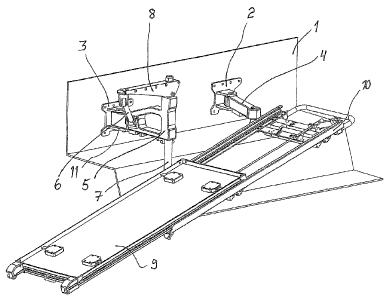
Figure 1 shows a stretcher base that can be attached to the wall of the
vehicle
which base has the position that is nearest to the wall.
Figure 2 shows the stretcher base of the figure 1 being moved a little bit
from the
wall.
Figure 3 shows the stretcher base of the figure 1 being moved from the wall to
a
nursing position.


CA 02759002 2011-10-17
WO 2010/043753 PCT/F12009/000090
3
Figure 4 shows the stretcher base of the figure 1 in the loading position.

In the figure 1 there is a stretcher base 9, 10 that is attached to the wall 1
of the vehicle
with the help of attachment fixtures 2 and 3 which stretcher base is adjusted
to be
moveable with the help of the first arm 4 and the second arm 5 that turn
supported by the
hinges. The arms 4 and 5 are being turned next to the wall 1 in which case the
base 9, 10
is next to the wall.

In the figure 2 the arms 4 and 5 are a little bit turned away out of the wall
in which case
also the base 9, 10 has moved a little bit from the wall. The base has moved
in horizontal
direction out of the wall.

In the figure 3 the base 9, 10 has moved so much out of the wall 1 in
horizontal direction
that it has reached a position in relation to the lengths of the first arm 4
and the second arm
5 and also regarding the distances of the pivots of their arms from the wall 1
in which
position it has the direction of the wall and has essentially the same height
as it had next to
the wall when it was at the start situation.

In this position the locking of the base to this position belongs to this
arrangement which
locking is realised with the help of the sector plate 11 attached to the
attachment element 3
and with the help of a interlocking bolt 12 that is protruded to its hole in
this position. This
position is an advantageous nursing position of a patient when such thing is
performed in
the vehicle.
In the figure 4 there is a situation where the base 9, 10 has been moved for
example by
pulling from the base and by pressing a little bit to the loading position.
The arrangement
according to the invention tilts the base 9, 10 when it is further transferred
from the
situation of the figure 3 in such a way that the turning movement of the arms
4 and 5
increases. A vertical elevation adjustment bar 7 that is mounted in bearings
to be sliding at
the end of the arm 5 belongs to the second arm 5 to the lower end of which
elevation
adjustment bar a horizontal balk that supports the base 9, 10 is adjusted.
When the
turning movement of the arms 4, 5 increases from the position of the figure 3
the elevation
adjustment bar 7 begins to move down lower at the end of the arm 5 due to the
fact that


CA 02759002 2011-10-17
WO 2010/043753 PCT/F12009/000090
4
another bar 6 is attached to the extension arm 8 attached to the upper end of
the mentioned
bar 7 the upper part of which bar is attached to the extension arm 8 with the
help of a
hinge and the lower part is attached to the arm 5 with the help of a hinge. In
the position of
the figure 3 the bar 6 is positioned nearly vertically in which case the
elevation adjustment
bar 7 is essentially in the upper position. When the arms 4 and 5 according to
the figure 4
are more turned and the base 9, 10 maintains its direction due to the choice
of lengths of
the arms 4, 5 the bar 6 is turned to a diagonal position and has pulled at the
same time the
elevation adjustment bar 7 to a lower position by force. Due to this the base
9, 10 is tilted
to an advantageous loading position.

A movable carriage 9 that is on top belongs knowingly to the stretcher base 10
that helps
during the loading process of the patient stretcher in which case the loading
can be
performed outside the vehicle. The moving of the base 9, 10 with the load to
the vehicle
becomes easier when a gas spring is installed with the elevation adjustment
bar 7 in order
to lighten the lifting of the base.

Also with the choosing of the lengths of the arms 4 and 5 one can have an
impact on the
fact that in the position of the figure 4 the base has a suitable direction
for example in
relation to the door of the vehicle or in relation of other constructions.

The arrangement is suitable for any kind of loading and moving of a platform,
a tray or
similar table with the load or without it from an advantageous, tilted
position up in
horizontal direction and further to be able to do even side movements.
30

Dessin représentatif
Une figure unique qui représente un dessin illustrant l'invention.
États administratifs

Pour une meilleure compréhension de l'état de la demande ou brevet qui figure sur cette page, la rubrique Mise en garde , et les descriptions de Brevet , États administratifs , Taxes périodiques et Historique des paiements devraient être consultées.

États administratifs

Titre Date
Date de délivrance prévu 2017-02-21
(86) Date de dépôt PCT 2009-10-16
(87) Date de publication PCT 2010-04-22
(85) Entrée nationale 2011-10-17
Requête d'examen 2014-10-15
(45) Délivré 2017-02-21

Historique d'abandonnement

Il n'y a pas d'historique d'abandonnement

Taxes périodiques

Dernier paiement au montant de 263,14 $ a été reçu le 2023-09-27


 Montants des taxes pour le maintien en état à venir

Description Date Montant
Prochain paiement si taxe applicable aux petites entités 2024-10-16 253,00 $
Prochain paiement si taxe générale 2024-10-16 624,00 $

Avis : Si le paiement en totalité n'a pas été reçu au plus tard à la date indiquée, une taxe supplémentaire peut être imposée, soit une des taxes suivantes :

  • taxe de rétablissement ;
  • taxe pour paiement en souffrance ; ou
  • taxe additionnelle pour le renversement d'une péremption réputée.

Les taxes sur les brevets sont ajustées au 1er janvier de chaque année. Les montants ci-dessus sont les montants actuels s'ils sont reçus au plus tard le 31 décembre de l'année en cours.
Veuillez vous référer à la page web des taxes sur les brevets de l'OPIC pour voir tous les montants actuels des taxes.

Historique des paiements

Type de taxes Anniversaire Échéance Montant payé Date payée
Rétablissement des droits 200,00 $ 2011-10-17
Le dépôt d'une demande de brevet 400,00 $ 2011-10-17
Taxe de maintien en état - Demande - nouvelle loi 2 2011-10-17 100,00 $ 2011-10-17
Taxe de maintien en état - Demande - nouvelle loi 3 2012-10-16 100,00 $ 2012-10-15
Taxe de maintien en état - Demande - nouvelle loi 4 2013-10-16 100,00 $ 2013-10-10
Requête d'examen 800,00 $ 2014-10-15
Taxe de maintien en état - Demande - nouvelle loi 5 2014-10-16 200,00 $ 2014-10-15
Taxe de maintien en état - Demande - nouvelle loi 6 2015-10-16 200,00 $ 2015-10-08
Taxe de maintien en état - Demande - nouvelle loi 7 2016-10-17 200,00 $ 2016-09-16
Taxe finale 300,00 $ 2017-01-05
Taxe de maintien en état - brevet - nouvelle loi 8 2017-10-16 200,00 $ 2017-10-10
Taxe de maintien en état - brevet - nouvelle loi 9 2018-10-16 200,00 $ 2018-10-09
Taxe de maintien en état - brevet - nouvelle loi 10 2019-10-16 250,00 $ 2019-10-04
Taxe de maintien en état - brevet - nouvelle loi 11 2020-10-16 255,00 $ 2021-03-12
Surtaxe pour omission de payer taxe de maintien en état - nouvelle Loi 2021-03-12 150,00 $ 2021-03-12
Taxe de maintien en état - brevet - nouvelle loi 12 2021-10-18 255,00 $ 2021-09-04
Taxe de maintien en état - brevet - nouvelle loi 13 2022-10-17 254,49 $ 2022-09-17
Taxe de maintien en état - brevet - nouvelle loi 14 2023-10-16 263,14 $ 2023-09-27
Titulaires au dossier

Les titulaires actuels et antérieures au dossier sont affichés en ordre alphabétique.

Titulaires actuels au dossier
FRESTEMS OY
Titulaires antérieures au dossier
S.O.
Les propriétaires antérieurs qui ne figurent pas dans la liste des « Propriétaires au dossier » apparaîtront dans d'autres documents au dossier.
Documents

Pour visionner les fichiers sélectionnés, entrer le code reCAPTCHA :


Pour visualiser une image, cliquer sur un lien dans la colonne description du document. Pour télécharger l'image (les images), cliquer l'une ou plusieurs cases à cocher dans la première colonne et ensuite cliquer sur le bouton "Télécharger sélection en format PDF (archive Zip)" ou le bouton "Télécharger sélection (en un fichier PDF fusionné)".

Liste des documents de brevet publiés et non publiés sur la BDBC .

Si vous avez des difficultés à accéder au contenu, veuillez communiquer avec le Centre de services à la clientèle au 1-866-997-1936, ou envoyer un courriel au Centre de service à la clientèle de l'OPIC.


Description du
Document 
Date
(yyyy-mm-dd) 
Nombre de pages   Taille de l'image (Ko) 
Paiement de taxe périodique 2021-09-04 1 28
Lettre du bureau 2021-11-30 1 185
Lettre de remise 2021-12-21 2 190
Paiement de taxe périodique 2022-09-17 1 25
Abrégé 2011-10-17 1 74
Revendications 2011-10-17 2 64
Dessins 2011-10-17 2 123
Description 2011-10-17 4 194
Dessins représentatifs 2011-12-22 1 28
Page couverture 2011-12-22 2 67
Revendications 2016-02-10 2 63
Dessins représentatifs 2017-01-18 1 24
Page couverture 2017-01-18 2 66
PCT 2011-10-17 10 272
Cession 2011-10-17 5 115
Demande d'examen 2015-08-11 5 245
Poursuite-Amendment 2014-10-15 1 44
Modification 2016-02-10 8 314
Taxes 2016-09-16 1 33
Taxe finale 2017-01-05 1 42
Paiement de taxe périodique 2023-09-27 1 27