Language selection

Search

Patent 2771565 Summary

Third-party information liability

Some of the information on this Web page has been provided by external sources. The Government of Canada is not responsible for the accuracy, reliability or currency of the information supplied by external sources. Users wishing to rely upon this information should consult directly with the source of the information. Content provided by external sources is not subject to official languages, privacy and accessibility requirements.

Claims and Abstract availability

Any discrepancies in the text and image of the Claims and Abstract are due to differing posting times. Text of the Claims and Abstract are posted:

  • At the time the application is open to public inspection;
  • At the time of issue of the patent (grant).
(12) Patent: (11) CA 2771565
(54) English Title: DRILLING DEVICE FOR DRILLING SIDE PORTIONS OF LARGE SECTION MEMBERS
(54) French Title: APPAREIL POUR PERCER LES PARTIES LATERALES DE SECTIONS LARGES
Status: Granted
Bibliographic Data
(51) International Patent Classification (IPC):
  • B23B 39/14 (2006.01)
  • B23B 39/16 (2006.01)
  • B23P 23/00 (2006.01)
  • B23Q 1/03 (2006.01)
(72) Inventors :
  • PIROVANO, ALESSANDRO (Italy)
(73) Owners :
  • FICEP S.P.A. (Italy)
(71) Applicants :
  • FICEP S.P.A. (Italy)
(74) Agent: KIRBY EADES GALE BAKER
(74) Associate agent:
(45) Issued: 2018-12-04
(22) Filed Date: 2012-03-21
(41) Open to Public Inspection: 2013-09-21
Examination requested: 2017-09-13
Availability of licence: N/A
(25) Language of filing: English

Patent Cooperation Treaty (PCT): No

(30) Application Priority Data: None

Abstracts

English Abstract


A device for drilling side portions of large section members, the device
being arranged in a cutting system for cutting individual section member
lengths, starting from a long section member, comprises a base
thereon swinging support arms extend, the support arms being
arranged with a V pattern enclosing an angle, each support arm
including a plurality of sliding rollers for causing the section member to
slide thereon, the swinging arms including guides slidably supporting a
controllably driven carriage operatively connected to a threaded screw,
each threaded screw being operatively connected to a controllable
motor, each carriage having a movable arm which may be controllably
displaced along guides and comprising parallel guides engaging a
drilling assembly operatively coupled to a driving shaft, each driving
shaft being operatively connected to a corresponding controllable
motor.


French Abstract

Linvention décrit un appareil pour percer des parties latérales déléments de section large, lappareil étant placé dans un système de coupe pour couper des longueurs délément de section individuelles, en commençant par un élément de section long, comprenant une base sur celui-ci, balançant des bras de support étendus, les bras de support étant placés avec un motif en V fermant à un angle, chaque bras de support comprenant une pluralité de rouleaux coulissants pour amener lélément de section à glisser sur celui-ci, les bras coulissants comprenant des guides supportant de manière coulissante une voiture entraînée par commande connectée de manière fonctionnelle à une vis filetée, chaque vis filetée étant connectée de manière fonctionnelle à un moteur réglable, chaque voiture ayant un bras mobile qui peut être déplacé de manière contrôlée le long de guides et comprenant des guides parallèles mettant en prise un appareil pour percer et coupler de manière fonctionnelle à un arbre dentraînement, chaque arbre dentraînement étant connecté de manière fonctionnelle à un moteur réglable correspondant.

Claims

Note: Claims are shown in the official language in which they were submitted.

- 6 -
C LAIMS
1 . A drlling device for drilling side portions of large section
members, said device being arranged in a cutting system for cutting
individual section member lengths, starting from a long section
member, said device comprising a base thereon swinging support
arms extend, said support arms being arranged with a V pattern
enclosing an angle, each said support arm including a plurality of
sliding rollers for causing said section member to slide thereon, said
swinging arms including guides slidably supporting a controllably
driven carriage operatively connected to a threaded screw, each
said threaded screw being operatively connected to a controllable
motor, each said carriage having a movable arm which may be
controllably displaced along guides and comprising parallel guides
engaging a drilling assembly, each drilling assembly being
operatively coupled to a driving shaft, each said driving shaft being
operatively connected to a corresponding controllable motor.
2. The drilling device, according to claim 1, wherein said arm,
respectively said arm, is slidable along guides, which are parallel to
a section member driving axis.

Description

Note: Descriptions are shown in the official language in which they were submitted.


CA 02771565 2012-03-21
1
DRILLING DEVICE FOR DRILLING SIDE PORTIONS OF
LARGE SECTION MEMBERS
BACKGROUND OF THE INVENTION
The present invention relates to a drilling device for drilling
side portions of large section members.
It is already known from prior art, to cut individual section
member lengths by a band sawing machine, starting from a
section member having a length of about 6 meters and more.
As it is also known, the single section member lengths are cut
through a making cutting line, the individual section member
lengths cut to a target measurement being then loaded in
succession into a drilling machine.
Moreover, outside of the section member cutting line, other
devices are also provided for performing beveling milling
operations on the vertex region where the section member
sides meet with one another.
It should be apparent that such a provision of further devices
outside of the section member cutting line, represents a
substantial drawback, since it is .necessary to drive the section
members being cut from the saw machine cutting line to
another machine for drilling, for example, the section member
side portions.

CA 02771565 2012-03-21
- 2 -
SUMMARY OF THE INVENTION
Thus, the aim of the present invention is to overcome the
above mentioned drawbacks and provide a section member
side drilling machine or device, which is adapted to drill,
respectively mill, the section member side portions
respectively at a section member vertex point and which
machine may be fitted to different section member angles, for
example 90 and 600 angles, while allowing the drilling tool
axis to be always held perpendicular to a corresponding
section member side and the section member vertex milling
tool to be held at the section member vertex.
The above aim is achieved by a drilling device for drilling side
portions of large section members, the device being arranged
in a cutting system for cutting individual section member
lengths, starting. from a long section member, said device
comprising a base thereon swinging support arms extend, the
support arms being arranged with a V pattern, enclosing an
angle a, each support arm including a plurality of sliding rollers
for causing the section member to slide thereon, the swinging
arms including guides slidably supporting a controllably driven
carriage operatively connected to a threaded screw, each
threaded screw being operatively connected to a controllable
motor, each carriage having a movable arm which may be
controllably displaced along guides and comprising parallel

CA 02771565 2012-03-21
=
=
- 3 -
guides engaging a drilling assembly, each drilling assembly
being operatively coupled to a driving shaft, each driving shaft
being operatively connected to a corresponding controllable
motor.
BRIEF DESCRIPTION OF THE DRAWINGS
Further advantages and characteristics of the present
invention will become more apparent hereinafter from the
following disclosure, claims and accompanying drawings.
The subject matter according to the present invention will be
disclosed in a more detailed manner hereinafter with reference
to the accompanying drawings, where:
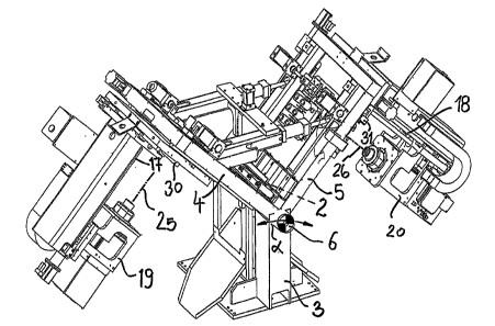
Figure 1 is a front view of the section member drilling device;
and
Figure 2 is a perspective view of the drilling device shown in
figure 1.
DESCRIPTION OF THE PREFERRED EMBODIMENT
With reference to figure 1 the device, being generally indicated
by the reference number 1 and arranged in a section member
cutting line 2, comprises a base 3, therefrom swinging support
arms .4 and 5 extend, said support arms having an adjustable
angular position and defining an angle a therebetween, as
shown in figure 1.
At the vertex 6, the arms 4 and 5 comprise a plurality of sliding
rollers 7 and 8 for facilitating the movement of the section
=

CA 02771565 2012-03-21
- 4 -
member 2.
The outer side of each arms 4, 5 supports precision guides 9
and 10 allowing a corresponding carriage 11, respectively 12,
to controllably slide therealong, as shown by the arrows (f) and
(9).
To that end the carriages 11 and 12 are operatively connected
to the shaft of a controllable driving motor 13, respectively 14,
each said motor 13 and 14 being arranged at the free end
portion of the arms 4, 5 and is operatively connected to the
system control assembly.
From each carriage or slide 11, 12, extends perpendicularly an
arm 15, 16 including parallel guides 17 and 18, therealong a
drilling assembly 19, 20, is slidably controllably driven in the
direction of the arrows (h) and (i).
The drilling assemblies 19 and 20 are operatively connected to
a corresponding driving threaded shaft 21 and 22, in turn
operatively connected to shaft driving controllable motors 23,
24, which are controlled, for example, by encoder means of a
per se known type, which are in turn operatively connected to
the system control means.
Each drilling assembly 19, 20 supports a machining tool 25, 26
=
schematically indicated by a dot and dash line.
Advantageously, the arm 15, respectively 16, is slidably driven
along guides 30, respectively 31, forming a complementary

CA 02771565 2012-03-21
=
=
- 5 -
axis parallel to the section member driving axis for performing
machining operations on a target area of the section member
2 without any need of relocating said section member 2.

Representative Drawing
A single figure which represents the drawing illustrating the invention.
Administrative Status

For a clearer understanding of the status of the application/patent presented on this page, the site Disclaimer , as well as the definitions for Patent , Administrative Status , Maintenance Fee  and Payment History  should be consulted.

Administrative Status

Title Date
Forecasted Issue Date 2018-12-04
(22) Filed 2012-03-21
(41) Open to Public Inspection 2013-09-21
Examination Requested 2017-09-13
(45) Issued 2018-12-04

Abandonment History

Abandonment Date Reason Reinstatement Date
2015-03-23 FAILURE TO PAY APPLICATION MAINTENANCE FEE 2015-07-07
2017-03-21 FAILURE TO REQUEST EXAMINATION 2017-09-13
2017-03-21 FAILURE TO PAY APPLICATION MAINTENANCE FEE 2017-09-12

Maintenance Fee

Last Payment of $347.00 was received on 2024-03-21


 Upcoming maintenance fee amounts

Description Date Amount
Next Payment if standard fee 2025-03-21 $347.00
Next Payment if small entity fee 2025-03-21 $125.00

Note : If the full payment has not been received on or before the date indicated, a further fee may be required which may be one of the following

  • the reinstatement fee;
  • the late payment fee; or
  • additional fee to reverse deemed expiry.

Patent fees are adjusted on the 1st of January every year. The amounts above are the current amounts if received by December 31 of the current year.
Please refer to the CIPO Patent Fees web page to see all current fee amounts.

Payment History

Fee Type Anniversary Year Due Date Amount Paid Paid Date
Application Fee $400.00 2012-03-21
Maintenance Fee - Application - New Act 2 2014-03-21 $100.00 2014-03-03
Reinstatement: Failure to Pay Application Maintenance Fees $200.00 2015-07-07
Maintenance Fee - Application - New Act 3 2015-03-23 $100.00 2015-07-07
Maintenance Fee - Application - New Act 4 2016-03-21 $100.00 2016-02-29
Reinstatement: Failure to Pay Application Maintenance Fees $200.00 2017-09-12
Maintenance Fee - Application - New Act 5 2017-03-21 $200.00 2017-09-12
Reinstatement - failure to request examination $200.00 2017-09-13
Request for Examination $800.00 2017-09-13
Maintenance Fee - Application - New Act 6 2018-03-21 $200.00 2018-02-28
Final Fee $300.00 2018-10-22
Maintenance Fee - Patent - New Act 7 2019-03-21 $200.00 2019-03-11
Maintenance Fee - Patent - New Act 8 2020-03-23 $200.00 2020-04-01
Maintenance Fee - Patent - New Act 9 2021-03-22 $204.00 2021-03-11
Maintenance Fee - Patent - New Act 10 2022-03-21 $254.49 2022-02-25
Maintenance Fee - Patent - New Act 11 2023-03-21 $263.14 2023-03-20
Maintenance Fee - Patent - New Act 12 2024-03-21 $347.00 2024-03-21
Owners on Record

Note: Records showing the ownership history in alphabetical order.

Current Owners on Record
FICEP S.P.A.
Past Owners on Record
None
Past Owners that do not appear in the "Owners on Record" listing will appear in other documentation within the application.
Documents

To view selected files, please enter reCAPTCHA code :


To view images, click a link in the Document Description column. To download the documents, select one or more checkboxes in the first column and then click the "Download Selected in PDF format (Zip Archive)" or the "Download Selected as Single PDF" button.

List of published and non-published patent-specific documents on the CPD .

If you have any difficulty accessing content, you can call the Client Service Centre at 1-866-997-1936 or send them an e-mail at CIPO Client Service Centre.


Document
Description 
Date
(yyyy-mm-dd) 
Number of pages   Size of Image (KB) 
Abstract 2012-03-21 1 29
Description 2012-03-21 5 147
Claims 2012-03-21 1 37
Drawings 2012-03-21 2 86
Representative Drawing 2013-08-26 1 33
Cover Page 2013-09-30 2 74
Maintenance Fee Payment 2017-09-12 1 33
Reinstatement / Request for Examination 2017-09-13 2 49
Amendment after Allowance 2018-07-23 6 135
Abstract 2018-07-23 1 24
Claims 2018-07-23 1 30
Acknowledgement of Acceptance of Amendment 2018-07-27 1 47
Final Fee 2018-10-22 2 50
Cover Page 2018-11-02 1 64
Assignment 2012-03-21 2 59
Maintenance Fee Payment 2024-03-21 1 33
Fees 2015-07-07 1 33