Sélection de la langue

Search

Sommaire du brevet 2771565 

Énoncé de désistement de responsabilité concernant l'information provenant de tiers

Une partie des informations de ce site Web a été fournie par des sources externes. Le gouvernement du Canada n'assume aucune responsabilité concernant la précision, l'actualité ou la fiabilité des informations fournies par les sources externes. Les utilisateurs qui désirent employer cette information devraient consulter directement la source des informations. Le contenu fourni par les sources externes n'est pas assujetti aux exigences sur les langues officielles, la protection des renseignements personnels et l'accessibilité.

Disponibilité de l'Abrégé et des Revendications

L'apparition de différences dans le texte et l'image des Revendications et de l'Abrégé dépend du moment auquel le document est publié. Les textes des Revendications et de l'Abrégé sont affichés :

  • lorsque la demande peut être examinée par le public;
  • lorsque le brevet est émis (délivrance).
(12) Brevet: (11) CA 2771565
(54) Titre français: APPAREIL POUR PERCER LES PARTIES LATERALES DE SECTIONS LARGES
(54) Titre anglais: DRILLING DEVICE FOR DRILLING SIDE PORTIONS OF LARGE SECTION MEMBERS
Statut: Octroyé
Données bibliographiques
(51) Classification internationale des brevets (CIB):
  • B23B 39/14 (2006.01)
  • B23B 39/16 (2006.01)
  • B23P 23/00 (2006.01)
  • B23Q 1/03 (2006.01)
(72) Inventeurs :
  • PIROVANO, ALESSANDRO (Italie)
(73) Titulaires :
  • FICEP S.P.A. (Italie)
(71) Demandeurs :
  • FICEP S.P.A. (Italie)
(74) Agent: KIRBY EADES GALE BAKER
(74) Co-agent:
(45) Délivré: 2018-12-04
(22) Date de dépôt: 2012-03-21
(41) Mise à la disponibilité du public: 2013-09-21
Requête d'examen: 2017-09-13
Licence disponible: S.O.
(25) Langue des documents déposés: Anglais

Traité de coopération en matière de brevets (PCT): Non

(30) Données de priorité de la demande: S.O.

Abrégés

Abrégé français

Linvention décrit un appareil pour percer des parties latérales déléments de section large, lappareil étant placé dans un système de coupe pour couper des longueurs délément de section individuelles, en commençant par un élément de section long, comprenant une base sur celui-ci, balançant des bras de support étendus, les bras de support étant placés avec un motif en V fermant à un angle, chaque bras de support comprenant une pluralité de rouleaux coulissants pour amener lélément de section à glisser sur celui-ci, les bras coulissants comprenant des guides supportant de manière coulissante une voiture entraînée par commande connectée de manière fonctionnelle à une vis filetée, chaque vis filetée étant connectée de manière fonctionnelle à un moteur réglable, chaque voiture ayant un bras mobile qui peut être déplacé de manière contrôlée le long de guides et comprenant des guides parallèles mettant en prise un appareil pour percer et coupler de manière fonctionnelle à un arbre dentraînement, chaque arbre dentraînement étant connecté de manière fonctionnelle à un moteur réglable correspondant.


Abrégé anglais


A device for drilling side portions of large section members, the device
being arranged in a cutting system for cutting individual section member
lengths, starting from a long section member, comprises a base
thereon swinging support arms extend, the support arms being
arranged with a V pattern enclosing an angle, each support arm
including a plurality of sliding rollers for causing the section member to
slide thereon, the swinging arms including guides slidably supporting a
controllably driven carriage operatively connected to a threaded screw,
each threaded screw being operatively connected to a controllable
motor, each carriage having a movable arm which may be controllably
displaced along guides and comprising parallel guides engaging a
drilling assembly operatively coupled to a driving shaft, each driving
shaft being operatively connected to a corresponding controllable
motor.

Revendications

Note : Les revendications sont présentées dans la langue officielle dans laquelle elles ont été soumises.


- 6 -
C LAIMS
1 . A drlling device for drilling side portions of large section
members, said device being arranged in a cutting system for cutting
individual section member lengths, starting from a long section
member, said device comprising a base thereon swinging support
arms extend, said support arms being arranged with a V pattern
enclosing an angle, each said support arm including a plurality of
sliding rollers for causing said section member to slide thereon, said
swinging arms including guides slidably supporting a controllably
driven carriage operatively connected to a threaded screw, each
said threaded screw being operatively connected to a controllable
motor, each said carriage having a movable arm which may be
controllably displaced along guides and comprising parallel guides
engaging a drilling assembly, each drilling assembly being
operatively coupled to a driving shaft, each said driving shaft being
operatively connected to a corresponding controllable motor.
2. The drilling device, according to claim 1, wherein said arm,
respectively said arm, is slidable along guides, which are parallel to
a section member driving axis.

Description

Note : Les descriptions sont présentées dans la langue officielle dans laquelle elles ont été soumises.

CA 02771565 2012-03-21
1
DRILLING DEVICE FOR DRILLING SIDE PORTIONS OF
LARGE SECTION MEMBERS
BACKGROUND OF THE INVENTION
The present invention relates to a drilling device for drilling
side portions of large section members.
It is already known from prior art, to cut individual section
member lengths by a band sawing machine, starting from a
section member having a length of about 6 meters and more.
As it is also known, the single section member lengths are cut
through a making cutting line, the individual section member
lengths cut to a target measurement being then loaded in
succession into a drilling machine.
Moreover, outside of the section member cutting line, other
devices are also provided for performing beveling milling
operations on the vertex region where the section member
sides meet with one another.
It should be apparent that such a provision of further devices
outside of the section member cutting line, represents a
substantial drawback, since it is .necessary to drive the section
members being cut from the saw machine cutting line to
another machine for drilling, for example, the section member
side portions.

CA 02771565 2012-03-21
- 2 -
SUMMARY OF THE INVENTION
Thus, the aim of the present invention is to overcome the
above mentioned drawbacks and provide a section member
side drilling machine or device, which is adapted to drill,
respectively mill, the section member side portions
respectively at a section member vertex point and which
machine may be fitted to different section member angles, for
example 90 and 600 angles, while allowing the drilling tool
axis to be always held perpendicular to a corresponding
section member side and the section member vertex milling
tool to be held at the section member vertex.
The above aim is achieved by a drilling device for drilling side
portions of large section members, the device being arranged
in a cutting system for cutting individual section member
lengths, starting. from a long section member, said device
comprising a base thereon swinging support arms extend, the
support arms being arranged with a V pattern, enclosing an
angle a, each support arm including a plurality of sliding rollers
for causing the section member to slide thereon, the swinging
arms including guides slidably supporting a controllably driven
carriage operatively connected to a threaded screw, each
threaded screw being operatively connected to a controllable
motor, each carriage having a movable arm which may be
controllably displaced along guides and comprising parallel

CA 02771565 2012-03-21
=
=
- 3 -
guides engaging a drilling assembly, each drilling assembly
being operatively coupled to a driving shaft, each driving shaft
being operatively connected to a corresponding controllable
motor.
BRIEF DESCRIPTION OF THE DRAWINGS
Further advantages and characteristics of the present
invention will become more apparent hereinafter from the
following disclosure, claims and accompanying drawings.
The subject matter according to the present invention will be
disclosed in a more detailed manner hereinafter with reference
to the accompanying drawings, where:
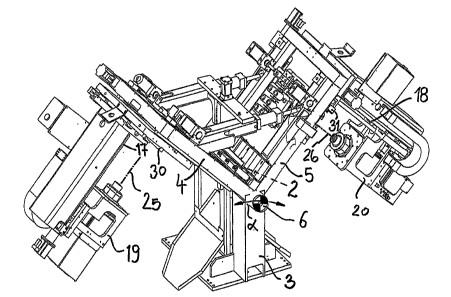
Figure 1 is a front view of the section member drilling device;
and
Figure 2 is a perspective view of the drilling device shown in
figure 1.
DESCRIPTION OF THE PREFERRED EMBODIMENT
With reference to figure 1 the device, being generally indicated
by the reference number 1 and arranged in a section member
cutting line 2, comprises a base 3, therefrom swinging support
arms .4 and 5 extend, said support arms having an adjustable
angular position and defining an angle a therebetween, as
shown in figure 1.
At the vertex 6, the arms 4 and 5 comprise a plurality of sliding
rollers 7 and 8 for facilitating the movement of the section
=

CA 02771565 2012-03-21
- 4 -
member 2.
The outer side of each arms 4, 5 supports precision guides 9
and 10 allowing a corresponding carriage 11, respectively 12,
to controllably slide therealong, as shown by the arrows (f) and
(9).
To that end the carriages 11 and 12 are operatively connected
to the shaft of a controllable driving motor 13, respectively 14,
each said motor 13 and 14 being arranged at the free end
portion of the arms 4, 5 and is operatively connected to the
system control assembly.
From each carriage or slide 11, 12, extends perpendicularly an
arm 15, 16 including parallel guides 17 and 18, therealong a
drilling assembly 19, 20, is slidably controllably driven in the
direction of the arrows (h) and (i).
The drilling assemblies 19 and 20 are operatively connected to
a corresponding driving threaded shaft 21 and 22, in turn
operatively connected to shaft driving controllable motors 23,
24, which are controlled, for example, by encoder means of a
per se known type, which are in turn operatively connected to
the system control means.
Each drilling assembly 19, 20 supports a machining tool 25, 26
=
schematically indicated by a dot and dash line.
Advantageously, the arm 15, respectively 16, is slidably driven
along guides 30, respectively 31, forming a complementary

CA 02771565 2012-03-21
=
=
- 5 -
axis parallel to the section member driving axis for performing
machining operations on a target area of the section member
2 without any need of relocating said section member 2.

Dessin représentatif
Une figure unique qui représente un dessin illustrant l'invention.
États administratifs

Pour une meilleure compréhension de l'état de la demande ou brevet qui figure sur cette page, la rubrique Mise en garde , et les descriptions de Brevet , États administratifs , Taxes périodiques et Historique des paiements devraient être consultées.

États administratifs

Titre Date
Date de délivrance prévu 2018-12-04
(22) Dépôt 2012-03-21
(41) Mise à la disponibilité du public 2013-09-21
Requête d'examen 2017-09-13
(45) Délivré 2018-12-04

Historique d'abandonnement

Date d'abandonnement Raison Reinstatement Date
2015-03-23 Taxe périodique sur la demande impayée 2015-07-07
2017-03-21 Absence de requête d'examen 2017-09-13
2017-03-21 Taxe périodique sur la demande impayée 2017-09-12

Taxes périodiques

Dernier paiement au montant de 347,00 $ a été reçu le 2024-03-21


 Montants des taxes pour le maintien en état à venir

Description Date Montant
Prochain paiement si taxe générale 2025-03-21 347,00 $
Prochain paiement si taxe applicable aux petites entités 2025-03-21 125,00 $

Avis : Si le paiement en totalité n'a pas été reçu au plus tard à la date indiquée, une taxe supplémentaire peut être imposée, soit une des taxes suivantes :

  • taxe de rétablissement ;
  • taxe pour paiement en souffrance ; ou
  • taxe additionnelle pour le renversement d'une péremption réputée.

Les taxes sur les brevets sont ajustées au 1er janvier de chaque année. Les montants ci-dessus sont les montants actuels s'ils sont reçus au plus tard le 31 décembre de l'année en cours.
Veuillez vous référer à la page web des taxes sur les brevets de l'OPIC pour voir tous les montants actuels des taxes.

Historique des paiements

Type de taxes Anniversaire Échéance Montant payé Date payée
Le dépôt d'une demande de brevet 400,00 $ 2012-03-21
Taxe de maintien en état - Demande - nouvelle loi 2 2014-03-21 100,00 $ 2014-03-03
Rétablissement: taxe de maintien en état non-payées pour la demande 200,00 $ 2015-07-07
Taxe de maintien en état - Demande - nouvelle loi 3 2015-03-23 100,00 $ 2015-07-07
Taxe de maintien en état - Demande - nouvelle loi 4 2016-03-21 100,00 $ 2016-02-29
Rétablissement: taxe de maintien en état non-payées pour la demande 200,00 $ 2017-09-12
Taxe de maintien en état - Demande - nouvelle loi 5 2017-03-21 200,00 $ 2017-09-12
Rétablissement - absence de requête d'examen 200,00 $ 2017-09-13
Requête d'examen 800,00 $ 2017-09-13
Taxe de maintien en état - Demande - nouvelle loi 6 2018-03-21 200,00 $ 2018-02-28
Taxe finale 300,00 $ 2018-10-22
Taxe de maintien en état - brevet - nouvelle loi 7 2019-03-21 200,00 $ 2019-03-11
Taxe de maintien en état - brevet - nouvelle loi 8 2020-03-23 200,00 $ 2020-04-01
Taxe de maintien en état - brevet - nouvelle loi 9 2021-03-22 204,00 $ 2021-03-11
Taxe de maintien en état - brevet - nouvelle loi 10 2022-03-21 254,49 $ 2022-02-25
Taxe de maintien en état - brevet - nouvelle loi 11 2023-03-21 263,14 $ 2023-03-20
Taxe de maintien en état - brevet - nouvelle loi 12 2024-03-21 347,00 $ 2024-03-21
Titulaires au dossier

Les titulaires actuels et antérieures au dossier sont affichés en ordre alphabétique.

Titulaires actuels au dossier
FICEP S.P.A.
Titulaires antérieures au dossier
S.O.
Les propriétaires antérieurs qui ne figurent pas dans la liste des « Propriétaires au dossier » apparaîtront dans d'autres documents au dossier.
Documents

Pour visionner les fichiers sélectionnés, entrer le code reCAPTCHA :


Pour visualiser une image, cliquer sur un lien dans la colonne description du document. Pour télécharger l'image (les images), cliquer l'une ou plusieurs cases à cocher dans la première colonne et ensuite cliquer sur le bouton "Télécharger sélection en format PDF (archive Zip)" ou le bouton "Télécharger sélection (en un fichier PDF fusionné)".

Liste des documents de brevet publiés et non publiés sur la BDBC .

Si vous avez des difficultés à accéder au contenu, veuillez communiquer avec le Centre de services à la clientèle au 1-866-997-1936, ou envoyer un courriel au Centre de service à la clientèle de l'OPIC.


Description du
Document 
Date
(yyyy-mm-dd) 
Nombre de pages   Taille de l'image (Ko) 
Abrégé 2012-03-21 1 29
Description 2012-03-21 5 147
Revendications 2012-03-21 1 37
Dessins 2012-03-21 2 86
Dessins représentatifs 2013-08-26 1 33
Page couverture 2013-09-30 2 74
Paiement de taxe périodique 2017-09-12 1 33
Rétablissement / Requête d'examen 2017-09-13 2 49
Modification après acceptation 2018-07-23 6 135
Abrégé 2018-07-23 1 24
Revendications 2018-07-23 1 30
Accusé d'autorisation des modifications 2018-07-27 1 47
Taxe finale 2018-10-22 2 50
Page couverture 2018-11-02 1 64
Cession 2012-03-21 2 59
Paiement de taxe périodique 2024-03-21 1 33
Taxes 2015-07-07 1 33