Language selection

Search

Patent 2775778 Summary

Third-party information liability

Some of the information on this Web page has been provided by external sources. The Government of Canada is not responsible for the accuracy, reliability or currency of the information supplied by external sources. Users wishing to rely upon this information should consult directly with the source of the information. Content provided by external sources is not subject to official languages, privacy and accessibility requirements.

Claims and Abstract availability

Any discrepancies in the text and image of the Claims and Abstract are due to differing posting times. Text of the Claims and Abstract are posted:

  • At the time the application is open to public inspection;
  • At the time of issue of the patent (grant).
(12) Patent Application: (11) CA 2775778
(54) English Title: GAS COMPRESSOR
(54) French Title: COMPRESSEUR A GAZ
Status: Dead
Bibliographic Data
(51) International Patent Classification (IPC):
  • F04B 27/06 (2006.01)
  • F04B 39/00 (2006.01)
(72) Inventors :
  • MADOCHE, JODY (Canada)
(73) Owners :
  • NEW AGE COMPRESSION LTD. (Canada)
(71) Applicants :
  • NEW AGE COMPRESSION LTD. (Canada)
(74) Agent: NA
(74) Associate agent: NA
(45) Issued:
(22) Filed Date: 2012-05-01
(41) Open to Public Inspection: 2013-11-01
Availability of licence: N/A
(25) Language of filing: English

Patent Cooperation Treaty (PCT): No

(30) Application Priority Data: None

Abstracts

English Abstract


A gas compressor has a housing and a rotary body within the housing. The
rotary
body has one or more pistons in piston chambers that are open to the outer
circumferential
surface. Each piston is rigidly secured to an engagement profile that extends
perpendicular to
the direction of the piston's travel. A stroke length control element is
connected to one or
more engagement profiles. As the rotary body rotates, the stroke length
control element
moves along the one or more engagement profiles. The stroke length of the
piston is
controlled by the position of the stroke length control element. The stroke
length control
element is biased toward an extended position buy is forced toward the central
axis to shorten
the stroke length of the piston upon application of a predetermined back
pressure.


Claims

Note: Claims are shown in the official language in which they were submitted.


7

What is claimed is:
1. A gas compressor, comprising:

a housing having a fluid inlet and a fluid outlet;
a rotary body housed within the housing, the rotary body having a central
axis, the
rotary body comprising:
an outer circumferential surface that is in communication with each of the
fluid inlet and a fluid outlet;
one or more piston chambers open to the outer circumferential surface, each
piston chamber housing a piston that reciprocates along a first direction in
the piston chamber;
one or more engagement profiles, each piston being rigidly secured to at least
one engagement profile, the engagement profile extending perpendicular to the
first direction
and the central axis on either side of the piston;
a driver for rotating the rotary body about a central axis;
a stroke length control element connected to one or more engagement profiles,
the
the stroke length control element moving along the one or more engagement
profiles;
a spring member that biases the stroke length control element toward an
extended
position away from the central axis, a stroke length of the piston being
controlled by the
position of the stroke length control element, the stroke length control
element being forced
toward the central axis to shorten the stroke length of the piston upon
application of a
predetermined back pressure to at least one piston as it reciprocates.
2. The gas compressor of claim 1, wherein the engagement profile is connected
between
two pistons.
3. The gas compressor of claim 1, wherein the stroke length control element
comprises a
slot and the stroke length control element comprises a sliding element that
engages the slot
and a shaft that rotatably engages the sliding element, the spring member
applying force to
the shaft.
4. A gas compressor, comprising:
a housing having a fluid inlet and a fluid outlet;


8
a rotary body housed within the housing, the rotary body having a central
axis, the
rotary body comprising:
an outer circumferential surface that is in communication with each of the
fluid inlet and the fluid outlet;
at least two piston chambers open to the outer circumferential surface and
extending in opposite directions, each piston chamber housing a piston that
reciprocates in a
first direction in the piston chamber;
one or more block members, each block member being rigidly attached
between a pair of pistons, the block member comprising a slot that extends
perpendicular to
the first direction and the central axis on either side of the piston;
a driver for rotating the rotary body about a central axis;
a pin that engages the stroke length control element connected to one or more
engagement profiles, the stroke length control element moving along the one or
more
engagement profiles;
a spring member that biases the stroke length control element toward an
extended
position away from the central axis, a stroke length of the piston being
controlled by the
position of the stroke length control elements, the stroke length control
element being forced
toward the central axis to shorten the stroke length of the piston upon
application of a
predetermined back pressure to the piston as it reciprocates.
5. A method of compressing gas from a source comprising a liquid component,
the
method comprising the steps of:
providing a gas compressor, comprising:
a housing having a fluid inlet and a fluid outlet;
a rotary body housed within the housing, the rotary body having a central
axis,
the rotary body comprising:
an outer circumferential surface that is in communication with each of
the fluid inlet and the fluid outlet;
one or more piston chambers open to the outer circumferential surface,
each piston chamber housing a piston that reciprocates in a first direction in
the piston
chamber;

9

one or more engagement profiles, each piston being rigidly secured to
an engagement profile, the engagement profile extending perpendicular to the
first direction
and the central axis on either side of the piston;
a driver for rotating the rotary body about a central axis;
a stroke length control element connected to one or more engagement profiles,
the stroke length control element moving along the one or more engagement
profiles;
a spring member that biases the stroke length control element toward an
extended position away from the central axis, a stroke length of the piston
being controlled by
the position of the stroke length control element;
connecting the fluid input to a source of fluid having a gas component and a
liquid
component;
connecting the fluid output to a body that receives compressed gas;
applying a predetermined biasing force via the spring member to set the
pressure
above which the stroke length of the piston is reduced;
driving the rotary body to cause the piston to draw in gas entering the fluid
inlet into
the piston chamber as the piston retracts and compressing the gas and
expelling the gas out of
the fluid outlet as the piston extends, the stroke length control element
being forced toward
the central axis to shorten the stroke length of the piston upon application
of a predetermined
back pressure due to the presence of liquid to the piston as it reciprocates.

6. The method of claim 5, wherein the engagement profile is connected between
two
pistons.

7. The gas compressor of claim 1, wherein the stroke length control element
comprises a
slot and the stroke length control element comprises a sliding element that
engages the slot
and a shaft that rotatably engages the sliding element, the spring member
applying a force to
the shaft.


Description

Note: Descriptions are shown in the official language in which they were submitted.


CA 02775775 201,05-01
T,LroL,E, Gas compreas...
"al:: ,1'25..assgTasb:::::::::::::"'"' "th " "m1)"""""t ma' be "" '
ba".7,/õ.7:::::::snin:::::11:07:7;7;ibileaõ..,,a0,..., type
-7'367 "" et a''' """ed
aax1','õitna::;:::::::Lis':Itaittfihat,:lia=s1:7:7,,,":11:.
icauc7.:7:1:::',E1:7:::::::::alrFidelot:',:lbate:',:h::::srti::::Pal:i,E.:17',E
FIraitilEbE

CA 02775778 2012-05-25
2
[0006] According to another aspect, the stroke length control element may
comprises a slot
and the stroke length control element may comprise a sliding element that
engages the slot
and a shaft that rotatably engages the block, the spring member applying a
force to the shaft.
[0007] According to another aspect, there is provided a method of compressing
gas from a
source comprising a liquid component, the method comprising the steps of
providing a gas
compressor as described above; connecting the fluid input to a source of fluid
having a gas
component and a liquid component; connecting the fluid output to a body that
receives
compressed gas; applying a predetermined biasing force via the spring member
to set the
pressure above which the stroke length of the piston is reduced; and driving
the rotary body to
cause the piston to draw in gas entering the fluid inlet onto the piston
chamber as the piston
retracts and compressing the gas and expelling the gas out the fluid outlet as
the piston
extends, the stroke length control element being forced toward the central
axis to shorten the
stroke length of the piston upon application of a predetermined back pressure
due to the
presence of liquid to the piston as it reciprocates.
BRIEF DESCRIPTION OF THE DRAWINGS
[0008] These and other features will become more apparent from the
following
description in which reference is made to the appended drawings, the drawings
are for the
purpose of illustration only and are not intended to be in any way limiting,
wherein:
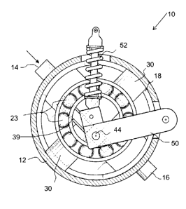
FIG. 1 is a side elevation view of the gas compressor with the cover removed,
where the stroke length control element is in an extended position.
FIG. 2 is a side elevation view in section of the gas compressor with the
stroke
length control element in an extended position and the rotary body in a first
rotary
position.
FIG. 3 is a side elevation view in section of the gas compressor with the
stroke
length control element in an extended position and the rotary body in a second

rotary position.
FIG. 4 is a side elevation view in section of the gas compressor with the
stroke
length control element in an extended position and the rotary body in a third
rotary
position.

CA 02775778 2012-05-25
3
FIG. 5 is a side elevation view in section of the gas compressor with the
stroke
length control element in a retracted position and the rotary body in a first
rotary
position.
FIG. 6 is a side elevation view in section of the gas compressor with the
stroke
length control element in a retracted position and the rotary body in a second
rotary position.
FIG. 7 is a side elevation view in section of the gas compressor with the
stroke
length control element in a retracted position and the rotary body in a third
rotary
position.
FIG. 8 is a perspective view of a gas compressor.
DETAILED DESCRIPTION
[0009] A gas compressor generally identified by reference numeral 10,
will now be
described with reference to FIG. 1 through 8.
Structure and Relationship of Parts:
[0010] Referring to FIG. 2, gas compressor 10 has a housing 12 with a
fluid inlet 14 and
a fluid outlet 16. A rotary body 18 is positioned within housing 12. Referring
to FIG. 3, fluid
inlet 14 connects to an inlet chamber 20 and fluid outlet 16 connects to an
outlet chamber 22.
Inlet and outlet chambers 20 and 22 are defined between the inner surface 24
of housing 12
and the outer circumferential surface 26 of rotary body 18. Rotary body 18
provides a seal
between chambers 20 and 22. Referring to FIG. I, rotary body 18 rotates on
bearings 23. As
used herein, the term "fluid" may include gas, liquid or combinations thereof.
[0011] Referring to FIG. 2, rotary body 18 as shown has two piston chambers
28 that are
open to outer circumferential surface 26 and thus in communication with inlet
and outlet
chambers 20 and 22 on an alternating basis as rotary body 18 rotates. Each
piston chamber
28 houses a piston 30 that reciprocates in the respective piston chamber 28.
As shown, piston
chambers 28 are parallel and coaxial on opposite sides of rotary body 18.
Pistons 30 are

CA _7_8_2 05 0,
õ
Eles:`,4:efEEE:airiverEaniFe.5,::`,17i.EYEivaei

`. :,1,:i::"--"'"le""1"s"'"'""-"
io
sb. is.
25
:,,107,77õ,õ,,eunderatooeithea,,,,,,,eaeoi.ecisprins,,,ashown,asprinmember

c..77577.20,2_05_0,
"
Representative Drawing
A single figure which represents the drawing illustrating the invention.
Administrative Status

For a clearer understanding of the status of the application/patent presented on this page, the site Disclaimer , as well as the definitions for Patent , Administrative Status , Maintenance Fee  and Payment History  should be consulted.

Administrative Status

Title Date
Forecasted Issue Date Unavailable
(22) Filed 2012-05-01
(41) Open to Public Inspection 2013-11-01
Dead Application 2018-05-01

Abandonment History

Abandonment Date Reason Reinstatement Date
2014-05-01 FAILURE TO PAY APPLICATION MAINTENANCE FEE 2014-07-10
2016-05-02 FAILURE TO PAY APPLICATION MAINTENANCE FEE 2017-04-24
2017-05-01 FAILURE TO REQUEST EXAMINATION
2017-08-04 FAILURE TO RESPOND TO OFFICE LETTER

Payment History

Fee Type Anniversary Year Due Date Amount Paid Paid Date
Registration of a document - section 124 $100.00 2012-05-01
Application Fee $200.00 2012-05-01
Back Payment of Fees $200.00 2013-10-15
Reinstatement: Failure to Pay Application Maintenance Fees $200.00 2014-07-10
Maintenance Fee - Application - New Act 2 2014-05-01 $50.00 2014-07-10
Maintenance Fee - Application - New Act 3 2015-05-01 $50.00 2015-05-01
Reinstatement: Failure to Pay Application Maintenance Fees $200.00 2017-04-24
Maintenance Fee - Application - New Act 4 2016-05-02 $50.00 2017-04-24
Maintenance Fee - Application - New Act 5 2017-05-01 $100.00 2017-04-24
Owners on Record

Note: Records showing the ownership history in alphabetical order.

Current Owners on Record
NEW AGE COMPRESSION LTD.
Past Owners on Record
None
Past Owners that do not appear in the "Owners on Record" listing will appear in other documentation within the application.
Documents

To view selected files, please enter reCAPTCHA code :


To view images, click a link in the Document Description column. To download the documents, select one or more checkboxes in the first column and then click the "Download Selected in PDF format (Zip Archive)" or the "Download Selected as Single PDF" button.

List of published and non-published patent-specific documents on the CPD .

If you have any difficulty accessing content, you can call the Client Service Centre at 1-866-997-1936 or send them an e-mail at CIPO Client Service Centre.


Document
Description 
Date
(yyyy-mm-dd) 
Number of pages   Size of Image (KB) 
Abstract 2012-05-01 1 10
Description 2012-05-01 6 152
Claims 2012-05-01 3 65
Drawings 2012-05-01 8 111
Representative Drawing 2013-10-04 1 14
Description 2012-05-25 6 199
Cover Page 2013-11-12 1 44
Abstract 2013-10-31 1 10
Claims 2013-10-31 3 65
Drawings 2013-10-31 8 111
Description 2013-10-31 6 199
Maintenance Fee Payment 2017-04-24 2 165
Correspondence 2012-05-15 1 25
Correspondence 2012-05-15 1 21
Correspondence 2012-05-15 1 49
Assignment 2012-05-01 5 76
Prosecution-Amendment 2012-05-25 5 157
Returned mail 2017-10-19 4 147
Correspondence 2013-08-23 1 27
Prosecution-Amendment 2013-10-04 5 144
Correspondence 2013-10-15 3 58
Correspondence 2013-10-23 1 29
Correspondence 2013-10-25 1 16
Fees 2015-05-01 1 33
Change of Agent 2017-03-15 1 21
Office Letter 2017-03-28 1 26
Change of Agent 2017-04-18 1 20
Office Letter 2017-05-04 1 21
Request for Appointment of Agent 2017-05-04 1 34