Sélection de la langue

Search

Sommaire du brevet 2775778 

Énoncé de désistement de responsabilité concernant l'information provenant de tiers

Une partie des informations de ce site Web a été fournie par des sources externes. Le gouvernement du Canada n'assume aucune responsabilité concernant la précision, l'actualité ou la fiabilité des informations fournies par les sources externes. Les utilisateurs qui désirent employer cette information devraient consulter directement la source des informations. Le contenu fourni par les sources externes n'est pas assujetti aux exigences sur les langues officielles, la protection des renseignements personnels et l'accessibilité.

Disponibilité de l'Abrégé et des Revendications

L'apparition de différences dans le texte et l'image des Revendications et de l'Abrégé dépend du moment auquel le document est publié. Les textes des Revendications et de l'Abrégé sont affichés :

  • lorsque la demande peut être examinée par le public;
  • lorsque le brevet est émis (délivrance).
(12) Demande de brevet: (11) CA 2775778
(54) Titre français: COMPRESSEUR A GAZ
(54) Titre anglais: GAS COMPRESSOR
Statut: Morte
Données bibliographiques
Abrégés

Abrégé anglais


A gas compressor has a housing and a rotary body within the housing. The
rotary
body has one or more pistons in piston chambers that are open to the outer
circumferential
surface. Each piston is rigidly secured to an engagement profile that extends
perpendicular to
the direction of the piston's travel. A stroke length control element is
connected to one or
more engagement profiles. As the rotary body rotates, the stroke length
control element
moves along the one or more engagement profiles. The stroke length of the
piston is
controlled by the position of the stroke length control element. The stroke
length control
element is biased toward an extended position buy is forced toward the central
axis to shorten
the stroke length of the piston upon application of a predetermined back
pressure.

Revendications

Note : Les revendications sont présentées dans la langue officielle dans laquelle elles ont été soumises.


7

What is claimed is:
1. A gas compressor, comprising:

a housing having a fluid inlet and a fluid outlet;
a rotary body housed within the housing, the rotary body having a central
axis, the
rotary body comprising:
an outer circumferential surface that is in communication with each of the
fluid inlet and a fluid outlet;
one or more piston chambers open to the outer circumferential surface, each
piston chamber housing a piston that reciprocates along a first direction in
the piston chamber;
one or more engagement profiles, each piston being rigidly secured to at least
one engagement profile, the engagement profile extending perpendicular to the
first direction
and the central axis on either side of the piston;
a driver for rotating the rotary body about a central axis;
a stroke length control element connected to one or more engagement profiles,
the
the stroke length control element moving along the one or more engagement
profiles;
a spring member that biases the stroke length control element toward an
extended
position away from the central axis, a stroke length of the piston being
controlled by the
position of the stroke length control element, the stroke length control
element being forced
toward the central axis to shorten the stroke length of the piston upon
application of a
predetermined back pressure to at least one piston as it reciprocates.
2. The gas compressor of claim 1, wherein the engagement profile is connected
between
two pistons.
3. The gas compressor of claim 1, wherein the stroke length control element
comprises a
slot and the stroke length control element comprises a sliding element that
engages the slot
and a shaft that rotatably engages the sliding element, the spring member
applying force to
the shaft.
4. A gas compressor, comprising:
a housing having a fluid inlet and a fluid outlet;


8
a rotary body housed within the housing, the rotary body having a central
axis, the
rotary body comprising:
an outer circumferential surface that is in communication with each of the
fluid inlet and the fluid outlet;
at least two piston chambers open to the outer circumferential surface and
extending in opposite directions, each piston chamber housing a piston that
reciprocates in a
first direction in the piston chamber;
one or more block members, each block member being rigidly attached
between a pair of pistons, the block member comprising a slot that extends
perpendicular to
the first direction and the central axis on either side of the piston;
a driver for rotating the rotary body about a central axis;
a pin that engages the stroke length control element connected to one or more
engagement profiles, the stroke length control element moving along the one or
more
engagement profiles;
a spring member that biases the stroke length control element toward an
extended
position away from the central axis, a stroke length of the piston being
controlled by the
position of the stroke length control elements, the stroke length control
element being forced
toward the central axis to shorten the stroke length of the piston upon
application of a
predetermined back pressure to the piston as it reciprocates.
5. A method of compressing gas from a source comprising a liquid component,
the
method comprising the steps of:
providing a gas compressor, comprising:
a housing having a fluid inlet and a fluid outlet;
a rotary body housed within the housing, the rotary body having a central
axis,
the rotary body comprising:
an outer circumferential surface that is in communication with each of
the fluid inlet and the fluid outlet;
one or more piston chambers open to the outer circumferential surface,
each piston chamber housing a piston that reciprocates in a first direction in
the piston
chamber;

9

one or more engagement profiles, each piston being rigidly secured to
an engagement profile, the engagement profile extending perpendicular to the
first direction
and the central axis on either side of the piston;
a driver for rotating the rotary body about a central axis;
a stroke length control element connected to one or more engagement profiles,
the stroke length control element moving along the one or more engagement
profiles;
a spring member that biases the stroke length control element toward an
extended position away from the central axis, a stroke length of the piston
being controlled by
the position of the stroke length control element;
connecting the fluid input to a source of fluid having a gas component and a
liquid
component;
connecting the fluid output to a body that receives compressed gas;
applying a predetermined biasing force via the spring member to set the
pressure
above which the stroke length of the piston is reduced;
driving the rotary body to cause the piston to draw in gas entering the fluid
inlet into
the piston chamber as the piston retracts and compressing the gas and
expelling the gas out of
the fluid outlet as the piston extends, the stroke length control element
being forced toward
the central axis to shorten the stroke length of the piston upon application
of a predetermined
back pressure due to the presence of liquid to the piston as it reciprocates.

6. The method of claim 5, wherein the engagement profile is connected between
two
pistons.

7. The gas compressor of claim 1, wherein the stroke length control element
comprises a
slot and the stroke length control element comprises a sliding element that
engages the slot
and a shaft that rotatably engages the sliding element, the spring member
applying a force to
the shaft.


Description

Note : Les descriptions sont présentées dans la langue officielle dans laquelle elles ont été soumises.


CA 02775775 201,05-01
T,LroL,E, Gas compreas...
"al:: ,1'25..assgTasb:::::::::::::"'"' "th " "m1)"""""t ma' be "" '
ba".7,/õ.7:::::::snin:::::11:07:7;7;ibileaõ..,,a0,..., type
-7'367 "" et a''' """ed
aax1','õitna::;:::::::Lis':Itaittfihat,:lia=s1:7:7,,,":11:.
icauc7.:7:1:::',E1:7:::::::::alrFidelot:',:lbate:',:h::::srti::::Pal:i,E.:17',E
FIraitilEbE

CA 02775778 2012-05-25
2
[0006] According to another aspect, the stroke length control element may
comprises a slot
and the stroke length control element may comprise a sliding element that
engages the slot
and a shaft that rotatably engages the block, the spring member applying a
force to the shaft.
[0007] According to another aspect, there is provided a method of compressing
gas from a
source comprising a liquid component, the method comprising the steps of
providing a gas
compressor as described above; connecting the fluid input to a source of fluid
having a gas
component and a liquid component; connecting the fluid output to a body that
receives
compressed gas; applying a predetermined biasing force via the spring member
to set the
pressure above which the stroke length of the piston is reduced; and driving
the rotary body to
cause the piston to draw in gas entering the fluid inlet onto the piston
chamber as the piston
retracts and compressing the gas and expelling the gas out the fluid outlet as
the piston
extends, the stroke length control element being forced toward the central
axis to shorten the
stroke length of the piston upon application of a predetermined back pressure
due to the
presence of liquid to the piston as it reciprocates.
BRIEF DESCRIPTION OF THE DRAWINGS
[0008] These and other features will become more apparent from the
following
description in which reference is made to the appended drawings, the drawings
are for the
purpose of illustration only and are not intended to be in any way limiting,
wherein:
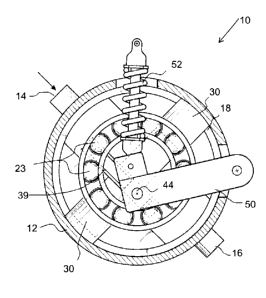
FIG. 1 is a side elevation view of the gas compressor with the cover removed,
where the stroke length control element is in an extended position.
FIG. 2 is a side elevation view in section of the gas compressor with the
stroke
length control element in an extended position and the rotary body in a first
rotary
position.
FIG. 3 is a side elevation view in section of the gas compressor with the
stroke
length control element in an extended position and the rotary body in a second

rotary position.
FIG. 4 is a side elevation view in section of the gas compressor with the
stroke
length control element in an extended position and the rotary body in a third
rotary
position.

CA 02775778 2012-05-25
3
FIG. 5 is a side elevation view in section of the gas compressor with the
stroke
length control element in a retracted position and the rotary body in a first
rotary
position.
FIG. 6 is a side elevation view in section of the gas compressor with the
stroke
length control element in a retracted position and the rotary body in a second
rotary position.
FIG. 7 is a side elevation view in section of the gas compressor with the
stroke
length control element in a retracted position and the rotary body in a third
rotary
position.
FIG. 8 is a perspective view of a gas compressor.
DETAILED DESCRIPTION
[0009] A gas compressor generally identified by reference numeral 10,
will now be
described with reference to FIG. 1 through 8.
Structure and Relationship of Parts:
[0010] Referring to FIG. 2, gas compressor 10 has a housing 12 with a
fluid inlet 14 and
a fluid outlet 16. A rotary body 18 is positioned within housing 12. Referring
to FIG. 3, fluid
inlet 14 connects to an inlet chamber 20 and fluid outlet 16 connects to an
outlet chamber 22.
Inlet and outlet chambers 20 and 22 are defined between the inner surface 24
of housing 12
and the outer circumferential surface 26 of rotary body 18. Rotary body 18
provides a seal
between chambers 20 and 22. Referring to FIG. I, rotary body 18 rotates on
bearings 23. As
used herein, the term "fluid" may include gas, liquid or combinations thereof.
[0011] Referring to FIG. 2, rotary body 18 as shown has two piston chambers
28 that are
open to outer circumferential surface 26 and thus in communication with inlet
and outlet
chambers 20 and 22 on an alternating basis as rotary body 18 rotates. Each
piston chamber
28 houses a piston 30 that reciprocates in the respective piston chamber 28.
As shown, piston
chambers 28 are parallel and coaxial on opposite sides of rotary body 18.
Pistons 30 are

CA _7_8_2 05 0,
õ
Eles:`,4:efEEE:airiverEaniFe.5,::`,17i.EYEivaei

`. :,1,:i::"--"'"le""1"s"'"'""-"
io
sb. is.
25
:,,107,77õ,õ,,eunderatooeithea,,,,,,,eaeoi.ecisprins,,,ashown,asprinmember

c..77577.20,2_05_0,
"
Dessin représentatif
Une figure unique qui représente un dessin illustrant l'invention.
États administratifs

Pour une meilleure compréhension de l'état de la demande ou brevet qui figure sur cette page, la rubrique Mise en garde , et les descriptions de Brevet , États administratifs , Taxes périodiques et Historique des paiements devraient être consultées.

États administratifs

Titre Date
Date de délivrance prévu Non disponible
(22) Dépôt 2012-05-01
(41) Mise à la disponibilité du public 2013-11-01
Demande morte 2018-05-01

Historique d'abandonnement

Date d'abandonnement Raison Reinstatement Date
2014-05-01 Taxe périodique sur la demande impayée 2014-07-10
2016-05-02 Taxe périodique sur la demande impayée 2017-04-24
2017-05-01 Absence de requête d'examen
2017-08-04 Absence de réponse à la lettre du bureau

Historique des paiements

Type de taxes Anniversaire Échéance Montant payé Date payée
Enregistrement de documents 100,00 $ 2012-05-01
Le dépôt d'une demande de brevet 200,00 $ 2012-05-01
Paiement des arriérés de taxes 200,00 $ 2013-10-15
Rétablissement: taxe de maintien en état non-payées pour la demande 200,00 $ 2014-07-10
Taxe de maintien en état - Demande - nouvelle loi 2 2014-05-01 50,00 $ 2014-07-10
Taxe de maintien en état - Demande - nouvelle loi 3 2015-05-01 50,00 $ 2015-05-01
Rétablissement: taxe de maintien en état non-payées pour la demande 200,00 $ 2017-04-24
Taxe de maintien en état - Demande - nouvelle loi 4 2016-05-02 50,00 $ 2017-04-24
Taxe de maintien en état - Demande - nouvelle loi 5 2017-05-01 100,00 $ 2017-04-24
Titulaires au dossier

Les titulaires actuels et antérieures au dossier sont affichés en ordre alphabétique.

Titulaires actuels au dossier
NEW AGE COMPRESSION LTD.
Titulaires antérieures au dossier
S.O.
Les propriétaires antérieurs qui ne figurent pas dans la liste des « Propriétaires au dossier » apparaîtront dans d'autres documents au dossier.
Documents

Pour visionner les fichiers sélectionnés, entrer le code reCAPTCHA :


Pour visualiser une image, cliquer sur un lien dans la colonne description du document. Pour télécharger l'image (les images), cliquer l'une ou plusieurs cases à cocher dans la première colonne et ensuite cliquer sur le bouton "Télécharger sélection en format PDF (archive Zip)" ou le bouton "Télécharger sélection (en un fichier PDF fusionné)".

Liste des documents de brevet publiés et non publiés sur la BDBC .

Si vous avez des difficultés à accéder au contenu, veuillez communiquer avec le Centre de services à la clientèle au 1-866-997-1936, ou envoyer un courriel au Centre de service à la clientèle de l'OPIC.


Description du
Document 
Date
(yyyy-mm-dd) 
Nombre de pages   Taille de l'image (Ko) 
Abrégé 2012-05-01 1 10
Description 2012-05-01 6 152
Revendications 2012-05-01 3 65
Dessins 2012-05-01 8 111
Dessins représentatifs 2013-10-04 1 14
Description 2012-05-25 6 199
Page couverture 2013-11-12 1 44
Abrégé 2013-10-31 1 10
Revendications 2013-10-31 3 65
Dessins 2013-10-31 8 111
Description 2013-10-31 6 199
Paiement de taxe périodique 2017-04-24 2 165
Correspondance 2012-05-15 1 25
Correspondance 2012-05-15 1 21
Correspondance 2012-05-15 1 49
Cession 2012-05-01 5 76
Poursuite-Amendment 2012-05-25 5 157
Courrier retourné 2017-10-19 4 147
Correspondance 2013-08-23 1 27
Poursuite-Amendment 2013-10-04 5 144
Correspondance 2013-10-15 3 58
Correspondance 2013-10-23 1 29
Correspondance 2013-10-25 1 16
Taxes 2015-05-01 1 33
Changement de nomination d'agent 2017-03-15 1 21
Lettre du bureau 2017-03-28 1 26
Changement de nomination d'agent 2017-04-18 1 20
Lettre du bureau 2017-05-04 1 21
Requête d'assignation d'un agent 2017-05-04 1 34