Language selection

Search

Patent 2779058 Summary

Third-party information liability

Some of the information on this Web page has been provided by external sources. The Government of Canada is not responsible for the accuracy, reliability or currency of the information supplied by external sources. Users wishing to rely upon this information should consult directly with the source of the information. Content provided by external sources is not subject to official languages, privacy and accessibility requirements.

Claims and Abstract availability

Any discrepancies in the text and image of the Claims and Abstract are due to differing posting times. Text of the Claims and Abstract are posted:

  • At the time the application is open to public inspection;
  • At the time of issue of the patent (grant).
(12) Patent: (11) CA 2779058
(54) English Title: PIPE COUPLING WITH SEAL PRESSING DEVICE
(54) French Title: RACCORD DE TUBE AVEC DISPOSITIF DE COMPRESSION DE JOINT
Status: Granted
Bibliographic Data
(51) International Patent Classification (IPC):
  • F16L 17/04 (2006.01)
  • F16L 21/06 (2006.01)
(72) Inventors :
  • KRAUSZ, ELIEZER (Israel)
  • CHIPROOT, AVI (Israel)
(73) Owners :
  • KRAUSZ INDUSTRIES DEVELOPMENT LTD. (Iceland)
(71) Applicants :
  • KRAUSZ INDUSTRIES DEVELOPMENT LTD. (Iceland)
(74) Agent: NORTON ROSE FULBRIGHT CANADA LLP/S.E.N.C.R.L., S.R.L.
(74) Associate agent:
(45) Issued: 2017-06-27
(86) PCT Filing Date: 2010-10-06
(87) Open to Public Inspection: 2011-05-05
Examination requested: 2015-09-29
Availability of licence: N/A
(25) Language of filing: English

Patent Cooperation Treaty (PCT): Yes
(86) PCT Filing Number: PCT/US2010/051562
(87) International Publication Number: WO2011/053437
(85) National Entry: 2012-04-26

(30) Application Priority Data:
Application No. Country/Territory Date
12/607,069 United States of America 2009-10-28

Abstracts

English Abstract

A seal pressing device (10) for a pipe coupling (30) including a sealing member (12) having an axial length and an outer curved contour (16) pressable against an inner diameter of a seal (32), the sealing member (12) having an axial row of mounting apertures (18) for receiving therein mechanical fasteners (19), and at least one winged extension (20, 22) extending from an end of the sealing member (12) bent inwards from the outer curved contour (16) of the sealing member (12).


French Abstract

L'invention porte sur un dispositif de compression de joint (10) pour un raccord de canalisation (30), qui comprend un élément d'étanchéité (12) ayant une certaine longueur axiale et un profil extérieur courbe (16) qui peut être comprimé contre une surface de diamètre intérieur d'un joint (32), l'élément d'étanchéité (12) possédant une rangée axiale d'ouvertures de montage (18) destinées à recevoir intérieurement des organes de fixation mécaniques (19), et au moins un prolongement (20, 22) muni d'ailes, qui s'étend à partir de l'extrémité de l'élément d'étanchéité (12) recourbée vers l'intérieur en partant du profil extérieur courbe (16) de l'élément d'étanchéité (12).

Claims

Note: Claims are shown in the official language in which they were submitted.

5
CLAIMS
What is claimed is:
1. A pipe coupling comprising:
an annular seal disposed in an annular clamp housing, said annular clamp
housing having an opening for inserting therein a pipe and comprising clamp
members and a tightening element that fastens and tightens said clamp members
towards each other in a direction transverse to an axial length of said
annular clamp
housing so as to apply a radially-inward clamping force on a pipe inserted in
said
opening; a seal pressing device including
a sealing member having an axial length and an outer curved contour that
presses against an inner diameter of said seal, the pipe coupling being
characterized in
that said sealing member has an axial row of mounting apertures for receiving
therein
mechanical fasteners; and in that
at least one winged extension is extending from an end of said sealing member
and is bent inwards from said outer curved contour of said sealing member.
2. The pipe coupling according to claim 1, comprising an axial crease
parallel to
the row of mounting apertures.
3. The pipe coupling according to claim 1, comprising an axial crease
positioned
between the row of mounting apertures and said at least one winged extension.
4. The pipe coupling according to claim 1, comprising two winged extensions

extending from ends of said sealing member on opposite sides of the row of
mounting
apertures.
5. The pipe -coupling according to claim 4, wherein one of said winged
extensions is closer to the row of mounting apertures than the other winged
extension.
6. The pipe coupling according to claim 1, wherein said at least one winged

extension has a curved extremity.

Description

Note: Descriptions are shown in the official language in which they were submitted.


CA 02779058 2012-04-26
WO 2011/053437
PCT/US2010/051562
1
PIPE COUPLING WITH SEAL PRESSING DEVICE
FIELD OF THE INVENTION
The present invention relates to a coupling for pipes, and particularly to a
device
for pressing against edges of a seal in a pipe coupling to ensure proper
sealing.
BACKGROUND OF THE INVENTION
Many kinds of removable band-type couplings for pipes exist in the art. It is
noted
that throughout the specification and claims, the term "pipe" encompasses any
kind of
generally cylindrical object.
For example, one commercially available type of pipe coupling has a seal clamp

housing. Clamp members are positioned face to face and a tightening element is
tightened
to press an annular seal element against the outside of the pipe inserted
through the seal
clamp housing.
In this type of pipe coupling, the seal has integrally formed rings at
opposite ends
of its axial length. The pipes that are inserted in the coupling contact these
rings. The
inner diameter of the rings can be adjusted to accommodate different outer
diameters of
pipes. The seal has an axial split along its length. The edges of the seal
along the split
either abut each other or overlap, and are pressed against each other when the
coupling is
tightened on the pipes. However, the rest of the axial length of the seal
between the rings
is thinner than the rings and does not contact the outer diameters of the
pipes inserted in
the coupling. Since the pipes do not contact the seal along most of the split,
a problem can
possibly occur wherein the edges of the seal along the split are not
adequately pressed
together to form the desired fluid-tight seal.
SUMMARY OF THE INVENTION
The present invention seeks to provide a device for pressing against edges of
a
seal in a pipe coupling to ensure proper sealing, as is described more in
detail further
below.
There is provided in accordance with an embodiment of the present invention a
seal pressing device for a pipe coupling including a sealing member having an
axial
length and an outer curved contour pressable against an inner diameter of a
seal, the
sealing member having an axial row of mounting apertures for receiving therein

mechanical fasteners, and at least one winged extension extending from an end
of the
sealing member bent inwards from the outer curved contour of the sealing
member.

CA 02779058 2012-04-26
WO 2011/053437
PCT/US2010/051562
2
In accordance with an embodiment of the present invention an axial crease is
parallel to the row of mounting apertures. The axial crease may be positioned
between the
row of mounting apertures and the at least one winged extension.
In accordance with an embodiment of the present invention two winged
extensions extend from ends of the sealing member on opposite sides of the row
of
mounting apertures. One of the winged extensions may be closer to the row of
mounting
apertures than the other winged extension.
BRIEF DESCRIPTION OF THE DRAWINGS
The present invention will be understood and appreciated more fully from the
following detailed description, taken in conjunction with the drawings in
which:
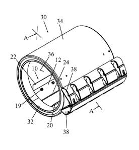
Fig. 1 is a simplified pictorial illustration of a seal pressing device,
constructed
and operative in accordance with a non-limiting embodiment of the present
invention;
Figs. 2A and 2B are simplified pictorial illustrations of the seal pressing
device of
Fig. 1 installed in a pipe coupling, in accordance with a non-limiting
embodiment of the
present invention;
Fig. 3 is a cross-sectional view taken along lines A-A in Fig. 2B; and
Fig. 4 is simplified pictorial illustration of a seal pressing device,
constructed and
operative in accordance with another non-limiting embodiment of the present
invention.
DETAILED DESCRIPTION OF EXEMPLARY EMBODIMENTS
Reference is now made to Fig. 1, which illustrates a seal pressing device 10,
constructed and operative in accordance with a non-limiting embodiment of the
present
invention.
Seal pressing device 10 includes a sealing member 12 having an axial length
along
a longitudinal axis 14 and an outer curved contour 16 pressable against an
inner diameter
of a seal (not shown here but seen in Figs. 2A-3). Sealing member 12 has an
axial row of
mounting apertures 18 for receiving therein mechanical fasteners 19 (such as
bolts,
screws or rivets and the like, not shown here but seen in Figs. 2A-3). One or
more winged
extensions 20 (or 22 in the drawing) extend from an end of sealing member 12
bent
inwards from the outer curved contour 16 of sealing member 12. In the non-
limiting
illustrated embodiment, there are two winged extensions 20 and 22 that extend
from ends
of sealing member 12 on opposite sides of the row of mounting apertures 18.
One of the
winged extensions 22 is closer to the row of mounting apertures 18 than the
other winged
extension 20.

CA 02779058 2016-12-13
3
Fig. 4. shows an alternative construction in which one or more winged
extensions
20 and 22 has a curved extremity 23, so that no sharp edges will dig into and
damage
softer material pipes (such as those made from plastic). It is noted that
winged extensions
20 and 22 may each include two portions separated by a gap, as shown in Fig.
4.
In accordance with an embodiment of the present invention an axial crease 24
is
parallel to the row of mounting apertures 18. The axial crease 24 is
positioned between
the row of mounting apertures 18 and winged extension 20.
Reference is now made to Figs. 2A, 2B and 3, which illustrate the seal
pressing
device 10 installed in a pipe coupling 30, in accordance with a non-limiting
embodiment
of the present invention.
Pipe coupling 30 includes an annular seal 32 disposed in an annular clamp
housing
34. Annular clamp housing 34 has an opening 36 for inserting therein a pipe
(not shown).
Annular clamp housing 34 has two clamp members 38 and a tightening element 40
(e.g.,
one or more mechanical fasteners, such as a bolt or screw and a tightening
nut, and
possibly washer) that fastens and tightens clamp members 38 towards each other
in a
direction transverse to the axial length of annular clamp housing 34 so as to
apply a
radially-inward clamping force on the pipe inserted in opening 36.
Annular seal 32, which may be made of a natural or artificial elastomeric
material,
is radially squeezed and sealingly clamped against the outside surface of the
pipe when
tightening element 40 fastens and tightens clamp members 38 towards each
other.
The pipe coupling may be of the type described in US Patent Application
20080012339 to the present inventors, filed on 5 March 2007, or in US Patent
7571940,
issued on 11 August 2009 to the present inventors. The present invention is
not limited to
these pipe couplings, however.
A pipe inserted in pipe coupling 30 is sealed by annular seal 32. The inserted
pipe
also presses against the winged extensions 20 and 22 of seal pressing device
10, which in
turn press against the axial edges of annular seal 32. The action of seal
pressing device 10
pressing against these edges insures a fluid-tight seal along the axial length
of seal 32.
Seal pressing device 10 may work satisfactorily in some applications with only
one
winged extension. However, in some applications, if only one winged extension
is used it
may cause a turning moment on the mechanical fasteners 19 at the edges of seal
32
and loosen the tightness of the fluid-tight seal. This is solved by using two
winged
extensions on opposite sides of the fasteners so that one winged extension
cancels the

CA 02779058 2012-04-26
WO 2011/053437
PCT/US2010/051562
4
turning moment of the other winged extension, and tightness of the fluid-tight
seal is
maintained.
The scope of the present invention includes both combinations and
subcombinations of the features described hereinabove as well as modifications
and
variations thereof which would occur to a person of skill in the art upon
reading the
foregoing description and which are not in the prior art.

Representative Drawing
A single figure which represents the drawing illustrating the invention.
Administrative Status

For a clearer understanding of the status of the application/patent presented on this page, the site Disclaimer , as well as the definitions for Patent , Administrative Status , Maintenance Fee  and Payment History  should be consulted.

Administrative Status

Title Date
Forecasted Issue Date 2017-06-27
(86) PCT Filing Date 2010-10-06
(87) PCT Publication Date 2011-05-05
(85) National Entry 2012-04-26
Examination Requested 2015-09-29
(45) Issued 2017-06-27

Abandonment History

There is no abandonment history.

Maintenance Fee

Last Payment of $263.14 was received on 2023-12-13


 Upcoming maintenance fee amounts

Description Date Amount
Next Payment if small entity fee 2025-10-06 $253.00
Next Payment if standard fee 2025-10-06 $624.00

Note : If the full payment has not been received on or before the date indicated, a further fee may be required which may be one of the following

  • the reinstatement fee;
  • the late payment fee; or
  • additional fee to reverse deemed expiry.

Patent fees are adjusted on the 1st of January every year. The amounts above are the current amounts if received by December 31 of the current year.
Please refer to the CIPO Patent Fees web page to see all current fee amounts.

Payment History

Fee Type Anniversary Year Due Date Amount Paid Paid Date
Application Fee $400.00 2012-04-26
Registration of a document - section 124 $100.00 2012-08-03
Maintenance Fee - Application - New Act 2 2012-10-09 $100.00 2012-09-20
Maintenance Fee - Application - New Act 3 2013-10-07 $100.00 2013-09-18
Maintenance Fee - Application - New Act 4 2014-10-06 $100.00 2014-09-19
Maintenance Fee - Application - New Act 5 2015-10-06 $200.00 2015-09-18
Request for Examination $800.00 2015-09-29
Maintenance Fee - Application - New Act 6 2016-10-06 $200.00 2016-09-21
Final Fee $300.00 2017-05-10
Maintenance Fee - Patent - New Act 7 2017-10-06 $200.00 2017-09-25
Maintenance Fee - Patent - New Act 8 2018-10-09 $200.00 2018-09-24
Maintenance Fee - Patent - New Act 9 2019-10-07 $200.00 2019-09-24
Maintenance Fee - Patent - New Act 10 2020-10-06 $250.00 2020-09-28
Maintenance Fee - Patent - New Act 11 2021-10-06 $255.00 2021-09-28
Maintenance Fee - Patent - New Act 12 2022-10-06 $254.49 2022-09-26
Maintenance Fee - Patent - New Act 13 2023-10-06 $263.14 2023-09-25
Maintenance Fee - Patent - New Act 14 2024-10-07 $263.14 2023-12-13
Owners on Record

Note: Records showing the ownership history in alphabetical order.

Current Owners on Record
KRAUSZ INDUSTRIES DEVELOPMENT LTD.
Past Owners on Record
None
Past Owners that do not appear in the "Owners on Record" listing will appear in other documentation within the application.
Documents

To view selected files, please enter reCAPTCHA code :


To view images, click a link in the Document Description column. To download the documents, select one or more checkboxes in the first column and then click the "Download Selected in PDF format (Zip Archive)" or the "Download Selected as Single PDF" button.

List of published and non-published patent-specific documents on the CPD .

If you have any difficulty accessing content, you can call the Client Service Centre at 1-866-997-1936 or send them an e-mail at CIPO Client Service Centre.


Document
Description 
Date
(yyyy-mm-dd) 
Number of pages   Size of Image (KB) 
Abstract 2012-04-26 1 64
Claims 2012-04-26 2 67
Drawings 2012-04-26 4 76
Description 2012-04-26 4 167
Representative Drawing 2012-04-26 1 15
Cover Page 2012-07-18 1 42
Description 2016-12-13 4 162
Claims 2016-12-13 1 33
Final Fee 2017-05-10 3 88
Representative Drawing 2017-05-26 1 10
Cover Page 2017-05-26 1 41
PCT 2012-04-26 8 277
Assignment 2012-04-26 4 133
Assignment 2012-08-03 4 98
Fees 2012-09-20 1 163
Fees 2013-09-18 1 33
Correspondence 2014-03-24 9 381
Correspondence 2014-04-11 1 17
Fees 2014-09-19 1 33
Fees 2015-09-18 1 33
Request for Examination 2015-09-29 2 69
Correspondence 2016-09-23 10 638
Examiner Requisition 2016-06-28 3 229
Fees 2016-09-21 1 33
Correspondence 2016-10-24 10 534
Office Letter 2016-11-03 1 36
Office Letter 2016-11-15 9 1,362
Amendment 2016-12-13 5 182
Office Letter 2017-02-10 1 30