Sélection de la langue

Search

Sommaire du brevet 2779058 

Énoncé de désistement de responsabilité concernant l'information provenant de tiers

Une partie des informations de ce site Web a été fournie par des sources externes. Le gouvernement du Canada n'assume aucune responsabilité concernant la précision, l'actualité ou la fiabilité des informations fournies par les sources externes. Les utilisateurs qui désirent employer cette information devraient consulter directement la source des informations. Le contenu fourni par les sources externes n'est pas assujetti aux exigences sur les langues officielles, la protection des renseignements personnels et l'accessibilité.

Disponibilité de l'Abrégé et des Revendications

L'apparition de différences dans le texte et l'image des Revendications et de l'Abrégé dépend du moment auquel le document est publié. Les textes des Revendications et de l'Abrégé sont affichés :

  • lorsque la demande peut être examinée par le public;
  • lorsque le brevet est émis (délivrance).
(12) Brevet: (11) CA 2779058
(54) Titre français: RACCORD DE TUBE AVEC DISPOSITIF DE COMPRESSION DE JOINT
(54) Titre anglais: PIPE COUPLING WITH SEAL PRESSING DEVICE
Statut: Octroyé
Données bibliographiques
(51) Classification internationale des brevets (CIB):
  • F16L 17/04 (2006.01)
  • F16L 21/06 (2006.01)
(72) Inventeurs :
  • KRAUSZ, ELIEZER (Israël)
  • CHIPROOT, AVI (Israël)
(73) Titulaires :
  • KRAUSZ INDUSTRIES DEVELOPMENT LTD. (Islande)
(71) Demandeurs :
  • KRAUSZ INDUSTRIES DEVELOPMENT LTD. (Islande)
(74) Agent: NORTON ROSE FULBRIGHT CANADA LLP/S.E.N.C.R.L., S.R.L.
(74) Co-agent:
(45) Délivré: 2017-06-27
(86) Date de dépôt PCT: 2010-10-06
(87) Mise à la disponibilité du public: 2011-05-05
Requête d'examen: 2015-09-29
Licence disponible: S.O.
(25) Langue des documents déposés: Anglais

Traité de coopération en matière de brevets (PCT): Oui
(86) Numéro de la demande PCT: PCT/US2010/051562
(87) Numéro de publication internationale PCT: WO2011/053437
(85) Entrée nationale: 2012-04-26

(30) Données de priorité de la demande:
Numéro de la demande Pays / territoire Date
12/607,069 Etats-Unis d'Amérique 2009-10-28

Abrégés

Abrégé français

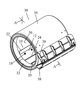
L'invention porte sur un dispositif de compression de joint (10) pour un raccord de canalisation (30), qui comprend un élément d'étanchéité (12) ayant une certaine longueur axiale et un profil extérieur courbe (16) qui peut être comprimé contre une surface de diamètre intérieur d'un joint (32), l'élément d'étanchéité (12) possédant une rangée axiale d'ouvertures de montage (18) destinées à recevoir intérieurement des organes de fixation mécaniques (19), et au moins un prolongement (20, 22) muni d'ailes, qui s'étend à partir de l'extrémité de l'élément d'étanchéité (12) recourbée vers l'intérieur en partant du profil extérieur courbe (16) de l'élément d'étanchéité (12).


Abrégé anglais

A seal pressing device (10) for a pipe coupling (30) including a sealing member (12) having an axial length and an outer curved contour (16) pressable against an inner diameter of a seal (32), the sealing member (12) having an axial row of mounting apertures (18) for receiving therein mechanical fasteners (19), and at least one winged extension (20, 22) extending from an end of the sealing member (12) bent inwards from the outer curved contour (16) of the sealing member (12).

Revendications

Note : Les revendications sont présentées dans la langue officielle dans laquelle elles ont été soumises.


5
CLAIMS
What is claimed is:
1. A pipe coupling comprising:
an annular seal disposed in an annular clamp housing, said annular clamp
housing having an opening for inserting therein a pipe and comprising clamp
members and a tightening element that fastens and tightens said clamp members
towards each other in a direction transverse to an axial length of said
annular clamp
housing so as to apply a radially-inward clamping force on a pipe inserted in
said
opening; a seal pressing device including
a sealing member having an axial length and an outer curved contour that
presses against an inner diameter of said seal, the pipe coupling being
characterized in
that said sealing member has an axial row of mounting apertures for receiving
therein
mechanical fasteners; and in that
at least one winged extension is extending from an end of said sealing member
and is bent inwards from said outer curved contour of said sealing member.
2. The pipe coupling according to claim 1, comprising an axial crease
parallel to
the row of mounting apertures.
3. The pipe coupling according to claim 1, comprising an axial crease
positioned
between the row of mounting apertures and said at least one winged extension.
4. The pipe coupling according to claim 1, comprising two winged extensions

extending from ends of said sealing member on opposite sides of the row of
mounting
apertures.
5. The pipe -coupling according to claim 4, wherein one of said winged
extensions is closer to the row of mounting apertures than the other winged
extension.
6. The pipe coupling according to claim 1, wherein said at least one winged

extension has a curved extremity.

Description

Note : Les descriptions sont présentées dans la langue officielle dans laquelle elles ont été soumises.


CA 02779058 2012-04-26
WO 2011/053437
PCT/US2010/051562
1
PIPE COUPLING WITH SEAL PRESSING DEVICE
FIELD OF THE INVENTION
The present invention relates to a coupling for pipes, and particularly to a
device
for pressing against edges of a seal in a pipe coupling to ensure proper
sealing.
BACKGROUND OF THE INVENTION
Many kinds of removable band-type couplings for pipes exist in the art. It is
noted
that throughout the specification and claims, the term "pipe" encompasses any
kind of
generally cylindrical object.
For example, one commercially available type of pipe coupling has a seal clamp

housing. Clamp members are positioned face to face and a tightening element is
tightened
to press an annular seal element against the outside of the pipe inserted
through the seal
clamp housing.
In this type of pipe coupling, the seal has integrally formed rings at
opposite ends
of its axial length. The pipes that are inserted in the coupling contact these
rings. The
inner diameter of the rings can be adjusted to accommodate different outer
diameters of
pipes. The seal has an axial split along its length. The edges of the seal
along the split
either abut each other or overlap, and are pressed against each other when the
coupling is
tightened on the pipes. However, the rest of the axial length of the seal
between the rings
is thinner than the rings and does not contact the outer diameters of the
pipes inserted in
the coupling. Since the pipes do not contact the seal along most of the split,
a problem can
possibly occur wherein the edges of the seal along the split are not
adequately pressed
together to form the desired fluid-tight seal.
SUMMARY OF THE INVENTION
The present invention seeks to provide a device for pressing against edges of
a
seal in a pipe coupling to ensure proper sealing, as is described more in
detail further
below.
There is provided in accordance with an embodiment of the present invention a
seal pressing device for a pipe coupling including a sealing member having an
axial
length and an outer curved contour pressable against an inner diameter of a
seal, the
sealing member having an axial row of mounting apertures for receiving therein

mechanical fasteners, and at least one winged extension extending from an end
of the
sealing member bent inwards from the outer curved contour of the sealing
member.

CA 02779058 2012-04-26
WO 2011/053437
PCT/US2010/051562
2
In accordance with an embodiment of the present invention an axial crease is
parallel to the row of mounting apertures. The axial crease may be positioned
between the
row of mounting apertures and the at least one winged extension.
In accordance with an embodiment of the present invention two winged
extensions extend from ends of the sealing member on opposite sides of the row
of
mounting apertures. One of the winged extensions may be closer to the row of
mounting
apertures than the other winged extension.
BRIEF DESCRIPTION OF THE DRAWINGS
The present invention will be understood and appreciated more fully from the
following detailed description, taken in conjunction with the drawings in
which:
Fig. 1 is a simplified pictorial illustration of a seal pressing device,
constructed
and operative in accordance with a non-limiting embodiment of the present
invention;
Figs. 2A and 2B are simplified pictorial illustrations of the seal pressing
device of
Fig. 1 installed in a pipe coupling, in accordance with a non-limiting
embodiment of the
present invention;
Fig. 3 is a cross-sectional view taken along lines A-A in Fig. 2B; and
Fig. 4 is simplified pictorial illustration of a seal pressing device,
constructed and
operative in accordance with another non-limiting embodiment of the present
invention.
DETAILED DESCRIPTION OF EXEMPLARY EMBODIMENTS
Reference is now made to Fig. 1, which illustrates a seal pressing device 10,
constructed and operative in accordance with a non-limiting embodiment of the
present
invention.
Seal pressing device 10 includes a sealing member 12 having an axial length
along
a longitudinal axis 14 and an outer curved contour 16 pressable against an
inner diameter
of a seal (not shown here but seen in Figs. 2A-3). Sealing member 12 has an
axial row of
mounting apertures 18 for receiving therein mechanical fasteners 19 (such as
bolts,
screws or rivets and the like, not shown here but seen in Figs. 2A-3). One or
more winged
extensions 20 (or 22 in the drawing) extend from an end of sealing member 12
bent
inwards from the outer curved contour 16 of sealing member 12. In the non-
limiting
illustrated embodiment, there are two winged extensions 20 and 22 that extend
from ends
of sealing member 12 on opposite sides of the row of mounting apertures 18.
One of the
winged extensions 22 is closer to the row of mounting apertures 18 than the
other winged
extension 20.

CA 02779058 2016-12-13
3
Fig. 4. shows an alternative construction in which one or more winged
extensions
20 and 22 has a curved extremity 23, so that no sharp edges will dig into and
damage
softer material pipes (such as those made from plastic). It is noted that
winged extensions
20 and 22 may each include two portions separated by a gap, as shown in Fig.
4.
In accordance with an embodiment of the present invention an axial crease 24
is
parallel to the row of mounting apertures 18. The axial crease 24 is
positioned between
the row of mounting apertures 18 and winged extension 20.
Reference is now made to Figs. 2A, 2B and 3, which illustrate the seal
pressing
device 10 installed in a pipe coupling 30, in accordance with a non-limiting
embodiment
of the present invention.
Pipe coupling 30 includes an annular seal 32 disposed in an annular clamp
housing
34. Annular clamp housing 34 has an opening 36 for inserting therein a pipe
(not shown).
Annular clamp housing 34 has two clamp members 38 and a tightening element 40
(e.g.,
one or more mechanical fasteners, such as a bolt or screw and a tightening
nut, and
possibly washer) that fastens and tightens clamp members 38 towards each other
in a
direction transverse to the axial length of annular clamp housing 34 so as to
apply a
radially-inward clamping force on the pipe inserted in opening 36.
Annular seal 32, which may be made of a natural or artificial elastomeric
material,
is radially squeezed and sealingly clamped against the outside surface of the
pipe when
tightening element 40 fastens and tightens clamp members 38 towards each
other.
The pipe coupling may be of the type described in US Patent Application
20080012339 to the present inventors, filed on 5 March 2007, or in US Patent
7571940,
issued on 11 August 2009 to the present inventors. The present invention is
not limited to
these pipe couplings, however.
A pipe inserted in pipe coupling 30 is sealed by annular seal 32. The inserted
pipe
also presses against the winged extensions 20 and 22 of seal pressing device
10, which in
turn press against the axial edges of annular seal 32. The action of seal
pressing device 10
pressing against these edges insures a fluid-tight seal along the axial length
of seal 32.
Seal pressing device 10 may work satisfactorily in some applications with only
one
winged extension. However, in some applications, if only one winged extension
is used it
may cause a turning moment on the mechanical fasteners 19 at the edges of seal
32
and loosen the tightness of the fluid-tight seal. This is solved by using two
winged
extensions on opposite sides of the fasteners so that one winged extension
cancels the

CA 02779058 2012-04-26
WO 2011/053437
PCT/US2010/051562
4
turning moment of the other winged extension, and tightness of the fluid-tight
seal is
maintained.
The scope of the present invention includes both combinations and
subcombinations of the features described hereinabove as well as modifications
and
variations thereof which would occur to a person of skill in the art upon
reading the
foregoing description and which are not in the prior art.

Dessin représentatif
Une figure unique qui représente un dessin illustrant l'invention.
États administratifs

Pour une meilleure compréhension de l'état de la demande ou brevet qui figure sur cette page, la rubrique Mise en garde , et les descriptions de Brevet , États administratifs , Taxes périodiques et Historique des paiements devraient être consultées.

États administratifs

Titre Date
Date de délivrance prévu 2017-06-27
(86) Date de dépôt PCT 2010-10-06
(87) Date de publication PCT 2011-05-05
(85) Entrée nationale 2012-04-26
Requête d'examen 2015-09-29
(45) Délivré 2017-06-27

Historique d'abandonnement

Il n'y a pas d'historique d'abandonnement

Taxes périodiques

Dernier paiement au montant de 263,14 $ a été reçu le 2023-12-13


 Montants des taxes pour le maintien en état à venir

Description Date Montant
Prochain paiement si taxe applicable aux petites entités 2025-10-06 253,00 $
Prochain paiement si taxe générale 2025-10-06 624,00 $

Avis : Si le paiement en totalité n'a pas été reçu au plus tard à la date indiquée, une taxe supplémentaire peut être imposée, soit une des taxes suivantes :

  • taxe de rétablissement ;
  • taxe pour paiement en souffrance ; ou
  • taxe additionnelle pour le renversement d'une péremption réputée.

Les taxes sur les brevets sont ajustées au 1er janvier de chaque année. Les montants ci-dessus sont les montants actuels s'ils sont reçus au plus tard le 31 décembre de l'année en cours.
Veuillez vous référer à la page web des taxes sur les brevets de l'OPIC pour voir tous les montants actuels des taxes.

Historique des paiements

Type de taxes Anniversaire Échéance Montant payé Date payée
Le dépôt d'une demande de brevet 400,00 $ 2012-04-26
Enregistrement de documents 100,00 $ 2012-08-03
Taxe de maintien en état - Demande - nouvelle loi 2 2012-10-09 100,00 $ 2012-09-20
Taxe de maintien en état - Demande - nouvelle loi 3 2013-10-07 100,00 $ 2013-09-18
Taxe de maintien en état - Demande - nouvelle loi 4 2014-10-06 100,00 $ 2014-09-19
Taxe de maintien en état - Demande - nouvelle loi 5 2015-10-06 200,00 $ 2015-09-18
Requête d'examen 800,00 $ 2015-09-29
Taxe de maintien en état - Demande - nouvelle loi 6 2016-10-06 200,00 $ 2016-09-21
Taxe finale 300,00 $ 2017-05-10
Taxe de maintien en état - brevet - nouvelle loi 7 2017-10-06 200,00 $ 2017-09-25
Taxe de maintien en état - brevet - nouvelle loi 8 2018-10-09 200,00 $ 2018-09-24
Taxe de maintien en état - brevet - nouvelle loi 9 2019-10-07 200,00 $ 2019-09-24
Taxe de maintien en état - brevet - nouvelle loi 10 2020-10-06 250,00 $ 2020-09-28
Taxe de maintien en état - brevet - nouvelle loi 11 2021-10-06 255,00 $ 2021-09-28
Taxe de maintien en état - brevet - nouvelle loi 12 2022-10-06 254,49 $ 2022-09-26
Taxe de maintien en état - brevet - nouvelle loi 13 2023-10-06 263,14 $ 2023-09-25
Taxe de maintien en état - brevet - nouvelle loi 14 2024-10-07 263,14 $ 2023-12-13
Titulaires au dossier

Les titulaires actuels et antérieures au dossier sont affichés en ordre alphabétique.

Titulaires actuels au dossier
KRAUSZ INDUSTRIES DEVELOPMENT LTD.
Titulaires antérieures au dossier
S.O.
Les propriétaires antérieurs qui ne figurent pas dans la liste des « Propriétaires au dossier » apparaîtront dans d'autres documents au dossier.
Documents

Pour visionner les fichiers sélectionnés, entrer le code reCAPTCHA :


Pour visualiser une image, cliquer sur un lien dans la colonne description du document. Pour télécharger l'image (les images), cliquer l'une ou plusieurs cases à cocher dans la première colonne et ensuite cliquer sur le bouton "Télécharger sélection en format PDF (archive Zip)" ou le bouton "Télécharger sélection (en un fichier PDF fusionné)".

Liste des documents de brevet publiés et non publiés sur la BDBC .

Si vous avez des difficultés à accéder au contenu, veuillez communiquer avec le Centre de services à la clientèle au 1-866-997-1936, ou envoyer un courriel au Centre de service à la clientèle de l'OPIC.


Description du
Document 
Date
(yyyy-mm-dd) 
Nombre de pages   Taille de l'image (Ko) 
Abrégé 2012-04-26 1 64
Revendications 2012-04-26 2 67
Dessins 2012-04-26 4 76
Description 2012-04-26 4 167
Dessins représentatifs 2012-04-26 1 15
Page couverture 2012-07-18 1 42
Description 2016-12-13 4 162
Revendications 2016-12-13 1 33
Taxe finale 2017-05-10 3 88
Dessins représentatifs 2017-05-26 1 10
Page couverture 2017-05-26 1 41
PCT 2012-04-26 8 277
Cession 2012-04-26 4 133
Cession 2012-08-03 4 98
Taxes 2012-09-20 1 163
Taxes 2013-09-18 1 33
Correspondance 2014-03-24 9 381
Correspondance 2014-04-11 1 17
Taxes 2014-09-19 1 33
Taxes 2015-09-18 1 33
Requête d'examen 2015-09-29 2 69
Correspondance 2016-09-23 10 638
Demande d'examen 2016-06-28 3 229
Taxes 2016-09-21 1 33
Correspondance 2016-10-24 10 534
Lettre du bureau 2016-11-03 1 36
Lettre du bureau 2016-11-15 9 1 362
Modification 2016-12-13 5 182
Lettre du bureau 2017-02-10 1 30