Language selection

Search

Patent 2862828 Summary

Third-party information liability

Some of the information on this Web page has been provided by external sources. The Government of Canada is not responsible for the accuracy, reliability or currency of the information supplied by external sources. Users wishing to rely upon this information should consult directly with the source of the information. Content provided by external sources is not subject to official languages, privacy and accessibility requirements.

Claims and Abstract availability

Any discrepancies in the text and image of the Claims and Abstract are due to differing posting times. Text of the Claims and Abstract are posted:

  • At the time the application is open to public inspection;
  • At the time of issue of the patent (grant).
(12) Patent: (11) CA 2862828
(54) English Title: SPINAL CAGE
(54) French Title: CAGE VERTEBRALE
Status: Granted
Bibliographic Data
(51) International Patent Classification (IPC):
  • A61F 2/44 (2006.01)
(72) Inventors :
  • ARNIN, URI (Israel)
(73) Owners :
  • APIFIX LTD. (Israel)
(71) Applicants :
  • APIFIX LTD. (Israel)
(74) Agent: NORTON ROSE FULBRIGHT CANADA LLP/S.E.N.C.R.L., S.R.L.
(74) Associate agent:
(45) Issued: 2019-03-19
(86) PCT Filing Date: 2013-01-07
(87) Open to Public Inspection: 2013-07-18
Examination requested: 2017-09-25
Availability of licence: N/A
(25) Language of filing: English

Patent Cooperation Treaty (PCT): Yes
(86) PCT Filing Number: PCT/US2013/020454
(87) International Publication Number: WO2013/106263
(85) National Entry: 2014-07-02

(30) Application Priority Data:
Application No. Country/Territory Date
61/631,667 United States of America 2012-01-09
61/690,835 United States of America 2012-07-06
61/743,418 United States of America 2012-09-04

Abstracts

English Abstract

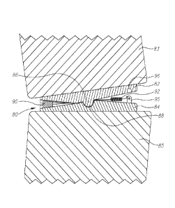
A spinal cage (80) including first and second spinal attachment members (82, 84) attachable to vertebrae (83, 85), the first and second spinal attachment members (82, 84) articulating with one another by means of an articulation joint (86, 88), characterised by a wedge element (90) arranged for wedging between the first and second spinal attachment members (82, 84), and an actuator (92) linked to the wedge element (90) for moving the wedge element (90) in a direction that wedges the wedge element (90) further in between the first and second spinal attachment members (82, 84) or further away from the first and second spinal attachment members (82, 84).


French Abstract

La présente invention concerne une cage vertébrale (80) comprenant des premier et second éléments de fixation vertébrale (82, 84) qui peuvent être reliés à des vertèbres (83, 85) et qui sont articulés les uns par rapport aux autres par le biais d'une articulation (86, 88), laquelle cage est caractérisée par un élément cale (90) conçu pour assurer le calage entre le premier et le second élément de fixation vertébrale (82, 84), ainsi qu'un actionneur (92) qui est relié à l'élément cale (90) et est conçu pour déplacer ce dernier dans une direction qui permet de caler plus loin l'élément cale (90) entre le premier et le second élément de fixation vertébrale (82, 84), ou de l'éloigner du premier et du second élément de fixation vertébrale (82, 84).

Claims

Note: Claims are shown in the official language in which they were submitted.


4

CLAIMS

What is claimed is:

1. A spinal cage comprising:
first and second spinal attachment members attachable to vertebrae, said first
and second
spinal attachment members articulating with one another by means of an
articulation joint; and
a wedge element arranged for wedging between said first and second spinal
attachment
members, and an actuator comprising a spring which is linked to said wedge
element for moving
said wedge element in a direction that wedges said wedge element further in
between said first
and second spinal attachment members or further away from said first and
second spinal
attachment members, wherein said articulation joint comprises a male member
which is pivotally
received in a female member.
2. The spinal cage according to claim 1, wherein said first and second
spinal attachment
members are formed with grooves for accommodating therein said wedge element.
3. The spinal cage according to claim 1, wherein said articulation joint
permits articulation
thereabout in one rotational degree of freedom.
4. The spinal cage according to claim 1, wherein said first and second
spinal attachment
members comprise flat plates.
5. The spinal cage according to claim 1, wherein a stopper is received in a
depression
provided on said first and second spinal attachment members.
6. The spinal cage according to claim 1, wherein said wedge element and
said spring are
positioned on opposite sides of said articulation joint.
7. The spinal cage according to claim 5, wherein said wedge element and
said stopper are
positioned on opposite sides of said articulation joint.

Description

Note: Descriptions are shown in the official language in which they were submitted.


CA 02862828 2014-07-02
WO 2013/106263 PCT/US2013/020454
1
SPINAL CAGE
FIELD OF THE INVENTION
The present invention relates generally to spinal implants and prostheses, and

particularly to a rotatable spinal cage.
BACKGROUND OF THE INVENTION
Scoliosis is a spinal deformity affecting many people. Current surgical
treatment
involves affixing long fusion rods to the spine by pedicle screws. The rod
system is
intended to force the deformed spine into a more healthy position. Other
spinal disorders
which are often treated by fusion include hyperkyphosis and hyperlordosis.
SUMMARY OF THE INVENTION
The present invention also seeks to provide an improved way to correct spinal
deformity by using a spinal cage inserted between adjacent vertebral bodies.
The spinal
cage is built in a way that it has a rotational pivot and a mechanism to allow
rotation in
one direction while preventing rotation in the opposite direction.
In one embodiment of the present invention, the spinal cage is rotated
(pivoted) by
a wedge that can slide or move towards the cage' s center of rotation along an
inclined
surface. The wedge can move by being pulled or pushed by an actuator (e.g.,
spring or
others). The wedge can also be activated, pushed or pulled, by a shaft,
through a
percutaneous procedure or by an implantable mechanism such as an electric
motor,
magnet arrangement or other means known to those skilled in the art.
In one embodiment of the present invention, the spinal cage may include a
ratchet
mechanism. After implanting the spinal cage, and after the patient has
recovered from the
operation, the patient is encouraged to bend to the corrective direction. The
rotatable
mechanism captures any minor incremental angular correction and then allows
the
patient's body to get used to the new position. This way, step by step in
small increments,
the deformity can be corrected.
BRIEF DESCRIPTION OF DRAWINGS
The present invention will be understood and appreciated more fully from the
following detailed description, taken in conjunction with the drawings in
which:
Fig. 1 is a simplified pictorial illustration of a longitudinal cross section
of a uni-
directional rotatable spinal cage, constructed and operative in accordance
with a non-
limiting embodiment of the present invention;

CA 02862828 2014-07-02
WO 2013/106263 PCT/US2013/020454
2
Fig. 2 is a simplified pictorial illustration of first and second spinal
attachment
members of the spinal cage of Fig. 1, in accordance with an embodiment of the
present
invention; and
Fig. 3 is a simplified pictorial illustration of the uni-directional rotatable
spinal
cage, constructed and operative in accordance with another embodiment of the
invention,
and including a ratchet mechanism.
DETAILED DESCRIPTION OF EMBODIMENTS
Reference is now made to Fig. 1, which illustrates a rotatable spinal cage 80,

constructed and operative in accordance with an embodiment of the invention.
Spinal cage 80 includes first and second spinal attachment members 82 and 84,
which may be, without limitation, flat plates. First and second spinal
attachment members
82 and 84 are attached to two adjacent vertebrae 83 and 85, respectively. The
plates may
have coarse or roughened surfaces that interface with the vertebrae for
enhanced binding
to the vertebra bone or tissue (other adhesion enhancers may be used as well,
such as
coatings for binding with tissue and the like). For example, fixation of
spinal cage 80 can
be enhanced by means of spikes, screws or other means known to those skilled
in the art.
First and second spinal attachment members 82 and 84 articulate with one
another
by means of an articulation joint. Accordingly, spinal cage 80 can pivot about
the
articulation joint in one rotational degree of freedom. In the illustrated
embodiment, the
articulation joint includes a male member 86 which is pivotally received in a
female
member 88. In the illustrated embodiment, the male member 86 extends from
first spinal
attachment member 82 and the female member 88 is formed in second spinal
attachment
member 84. Of course, the reverse can also be made.
A wedge element 90 is arranged for wedging between first and second spinal
attachment members 82 and 84. Wedge element 90 may have a generally conical or

trapezoidal shape or any other shape that can be accommodated by first and
second spinal
attachment members 82 and 84. An actuator 92 is linked to wedge element 90 for
moving
wedge element 90 in a direction that wedges wedge element 90 further in
between
members 82 and 84 (i.e., increases the wedging effect) or further away from
members 82
and 84 (i.e., decreases the wedging effect). Actuator 92 can be, without
limitation, a
spring, motor, linear actuator, solenoid and the like. Actuator 92 can pull or
push wedge
element 90 directly or through a string, rod or any other connecting element.
The surfaces of first and second spinal attachment members 82 and 84 that
contact
wedge element 90 can be polished, roughened, grooved, etc., to increase the
friction

CA 02862828 2014-07-02
WO 2013/106263 PCT/US2013/020454
3
between the wedge and the members. In one embodiment, wedge element 90 can
have a
threaded hole, pin, groove and the like, for grasping with a tool to enable
pulling the
wedge and to release the uni-directional mechanism and allow some rotation of
the
attachment members 82 and 84 to another direction.
Referring now to Fig. 2, it is seen that first and second spinal attachment
members
82 and 84 may be formed with grooves 94 for accommodating therein wedge
element 90
(not shown in Fig. 2). A stopper 95 which is received in a depression 96 may
be provided
on first and second spinal attachment members 82 and 84. Actuator 92 may be
attached to
stopper 95, as seen in Fig. 1. Stopper may be used to limit the pivoting
motion of spinal
cage 80.
Reference is now made to Fig. 3, which illustrates another version rotatable
spinal
cage 80, constructed and operative in accordance with an embodiment of the
invention. In
this embodiment, a ratchet mechanism 100, including a pawl 102 and tooth rack
104 are
mounted on first and second spinal attachment members 82 and 84. In this
manner, spinal
cage 80 may be rotated and locked in any desired rotational orientation.

Representative Drawing
A single figure which represents the drawing illustrating the invention.
Administrative Status

For a clearer understanding of the status of the application/patent presented on this page, the site Disclaimer , as well as the definitions for Patent , Administrative Status , Maintenance Fee  and Payment History  should be consulted.

Administrative Status

Title Date
Forecasted Issue Date 2019-03-19
(86) PCT Filing Date 2013-01-07
(87) PCT Publication Date 2013-07-18
(85) National Entry 2014-07-02
Examination Requested 2017-09-25
(45) Issued 2019-03-19

Abandonment History

There is no abandonment history.

Maintenance Fee

Last Payment of $263.14 was received on 2023-12-18


 Upcoming maintenance fee amounts

Description Date Amount
Next Payment if small entity fee 2025-01-07 $125.00
Next Payment if standard fee 2025-01-07 $347.00

Note : If the full payment has not been received on or before the date indicated, a further fee may be required which may be one of the following

  • the reinstatement fee;
  • the late payment fee; or
  • additional fee to reverse deemed expiry.

Patent fees are adjusted on the 1st of January every year. The amounts above are the current amounts if received by December 31 of the current year.
Please refer to the CIPO Patent Fees web page to see all current fee amounts.

Payment History

Fee Type Anniversary Year Due Date Amount Paid Paid Date
Application Fee $400.00 2014-07-02
Registration of a document - section 124 $100.00 2014-10-07
Maintenance Fee - Application - New Act 2 2015-01-07 $100.00 2014-12-30
Maintenance Fee - Application - New Act 3 2016-01-07 $100.00 2015-12-23
Maintenance Fee - Application - New Act 4 2017-01-09 $100.00 2016-12-29
Request for Examination $800.00 2017-09-25
Maintenance Fee - Application - New Act 5 2018-01-08 $200.00 2017-11-21
Maintenance Fee - Application - New Act 6 2019-01-07 $200.00 2018-11-28
Final Fee $300.00 2019-01-30
Maintenance Fee - Patent - New Act 7 2020-01-07 $200.00 2020-01-06
Maintenance Fee - Patent - New Act 8 2021-01-07 $200.00 2020-12-30
Maintenance Fee - Patent - New Act 9 2022-01-07 $203.59 2022-01-04
Maintenance Fee - Patent - New Act 10 2023-01-09 $254.49 2022-12-22
Maintenance Fee - Patent - New Act 11 2024-01-08 $263.14 2023-12-18
Owners on Record

Note: Records showing the ownership history in alphabetical order.

Current Owners on Record
APIFIX LTD.
Past Owners on Record
None
Past Owners that do not appear in the "Owners on Record" listing will appear in other documentation within the application.
Documents

To view selected files, please enter reCAPTCHA code :


To view images, click a link in the Document Description column. To download the documents, select one or more checkboxes in the first column and then click the "Download Selected in PDF format (Zip Archive)" or the "Download Selected as Single PDF" button.

List of published and non-published patent-specific documents on the CPD .

If you have any difficulty accessing content, you can call the Client Service Centre at 1-866-997-1936 or send them an e-mail at CIPO Client Service Centre.


Document
Description 
Date
(yyyy-mm-dd) 
Number of pages   Size of Image (KB) 
Abstract 2014-07-02 2 75
Claims 2014-07-02 1 39
Drawings 2014-07-02 3 48
Description 2014-07-02 3 136
Representative Drawing 2014-09-19 1 14
Cover Page 2014-10-14 2 52
Request for Examination 2017-09-25 3 85
Maintenance Fee Payment 2017-11-21 1 33
Claims 2018-11-13 1 35
Examiner Requisition 2018-05-22 3 185
Amendment 2018-11-13 4 128
Final Fee 2019-01-30 3 84
Representative Drawing 2019-02-18 1 14
Cover Page 2019-02-18 1 45
PCT 2014-07-02 3 84
Assignment 2014-07-02 7 249
Assignment 2014-10-07 5 162
Fees 2014-12-30 1 33
Fees 2015-12-23 1 33
Correspondence 2016-09-23 10 638
Correspondence 2016-10-24 10 534
Office Letter 2016-11-04 1 37
Office Letter 2016-11-15 9 1,362
Fees 2016-12-29 1 33
Office Letter 2017-02-10 1 30