Sélection de la langue

Search

Sommaire du brevet 2862828 

Énoncé de désistement de responsabilité concernant l'information provenant de tiers

Une partie des informations de ce site Web a été fournie par des sources externes. Le gouvernement du Canada n'assume aucune responsabilité concernant la précision, l'actualité ou la fiabilité des informations fournies par les sources externes. Les utilisateurs qui désirent employer cette information devraient consulter directement la source des informations. Le contenu fourni par les sources externes n'est pas assujetti aux exigences sur les langues officielles, la protection des renseignements personnels et l'accessibilité.

Disponibilité de l'Abrégé et des Revendications

L'apparition de différences dans le texte et l'image des Revendications et de l'Abrégé dépend du moment auquel le document est publié. Les textes des Revendications et de l'Abrégé sont affichés :

  • lorsque la demande peut être examinée par le public;
  • lorsque le brevet est émis (délivrance).
(12) Brevet: (11) CA 2862828
(54) Titre français: CAGE VERTEBRALE
(54) Titre anglais: SPINAL CAGE
Statut: Octroyé
Données bibliographiques
(51) Classification internationale des brevets (CIB):
  • A61F 2/44 (2006.01)
(72) Inventeurs :
  • ARNIN, URI (Israël)
(73) Titulaires :
  • APIFIX LTD. (Israël)
(71) Demandeurs :
  • APIFIX LTD. (Israël)
(74) Agent: NORTON ROSE FULBRIGHT CANADA LLP/S.E.N.C.R.L., S.R.L.
(74) Co-agent:
(45) Délivré: 2019-03-19
(86) Date de dépôt PCT: 2013-01-07
(87) Mise à la disponibilité du public: 2013-07-18
Requête d'examen: 2017-09-25
Licence disponible: S.O.
(25) Langue des documents déposés: Anglais

Traité de coopération en matière de brevets (PCT): Oui
(86) Numéro de la demande PCT: PCT/US2013/020454
(87) Numéro de publication internationale PCT: WO2013/106263
(85) Entrée nationale: 2014-07-02

(30) Données de priorité de la demande:
Numéro de la demande Pays / territoire Date
61/631,667 Etats-Unis d'Amérique 2012-01-09
61/690,835 Etats-Unis d'Amérique 2012-07-06
61/743,418 Etats-Unis d'Amérique 2012-09-04

Abrégés

Abrégé français

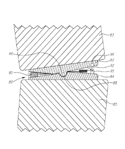
La présente invention concerne une cage vertébrale (80) comprenant des premier et second éléments de fixation vertébrale (82, 84) qui peuvent être reliés à des vertèbres (83, 85) et qui sont articulés les uns par rapport aux autres par le biais d'une articulation (86, 88), laquelle cage est caractérisée par un élément cale (90) conçu pour assurer le calage entre le premier et le second élément de fixation vertébrale (82, 84), ainsi qu'un actionneur (92) qui est relié à l'élément cale (90) et est conçu pour déplacer ce dernier dans une direction qui permet de caler plus loin l'élément cale (90) entre le premier et le second élément de fixation vertébrale (82, 84), ou de l'éloigner du premier et du second élément de fixation vertébrale (82, 84).


Abrégé anglais

A spinal cage (80) including first and second spinal attachment members (82, 84) attachable to vertebrae (83, 85), the first and second spinal attachment members (82, 84) articulating with one another by means of an articulation joint (86, 88), characterised by a wedge element (90) arranged for wedging between the first and second spinal attachment members (82, 84), and an actuator (92) linked to the wedge element (90) for moving the wedge element (90) in a direction that wedges the wedge element (90) further in between the first and second spinal attachment members (82, 84) or further away from the first and second spinal attachment members (82, 84).

Revendications

Note : Les revendications sont présentées dans la langue officielle dans laquelle elles ont été soumises.


4

CLAIMS

What is claimed is:

1. A spinal cage comprising:
first and second spinal attachment members attachable to vertebrae, said first
and second
spinal attachment members articulating with one another by means of an
articulation joint; and
a wedge element arranged for wedging between said first and second spinal
attachment
members, and an actuator comprising a spring which is linked to said wedge
element for moving
said wedge element in a direction that wedges said wedge element further in
between said first
and second spinal attachment members or further away from said first and
second spinal
attachment members, wherein said articulation joint comprises a male member
which is pivotally
received in a female member.
2. The spinal cage according to claim 1, wherein said first and second
spinal attachment
members are formed with grooves for accommodating therein said wedge element.
3. The spinal cage according to claim 1, wherein said articulation joint
permits articulation
thereabout in one rotational degree of freedom.
4. The spinal cage according to claim 1, wherein said first and second
spinal attachment
members comprise flat plates.
5. The spinal cage according to claim 1, wherein a stopper is received in a
depression
provided on said first and second spinal attachment members.
6. The spinal cage according to claim 1, wherein said wedge element and
said spring are
positioned on opposite sides of said articulation joint.
7. The spinal cage according to claim 5, wherein said wedge element and
said stopper are
positioned on opposite sides of said articulation joint.

Description

Note : Les descriptions sont présentées dans la langue officielle dans laquelle elles ont été soumises.

CA 02862828 2014-07-02
WO 2013/106263 PCT/US2013/020454
1
SPINAL CAGE
FIELD OF THE INVENTION
The present invention relates generally to spinal implants and prostheses, and

particularly to a rotatable spinal cage.
BACKGROUND OF THE INVENTION
Scoliosis is a spinal deformity affecting many people. Current surgical
treatment
involves affixing long fusion rods to the spine by pedicle screws. The rod
system is
intended to force the deformed spine into a more healthy position. Other
spinal disorders
which are often treated by fusion include hyperkyphosis and hyperlordosis.
SUMMARY OF THE INVENTION
The present invention also seeks to provide an improved way to correct spinal
deformity by using a spinal cage inserted between adjacent vertebral bodies.
The spinal
cage is built in a way that it has a rotational pivot and a mechanism to allow
rotation in
one direction while preventing rotation in the opposite direction.
In one embodiment of the present invention, the spinal cage is rotated
(pivoted) by
a wedge that can slide or move towards the cage' s center of rotation along an
inclined
surface. The wedge can move by being pulled or pushed by an actuator (e.g.,
spring or
others). The wedge can also be activated, pushed or pulled, by a shaft,
through a
percutaneous procedure or by an implantable mechanism such as an electric
motor,
magnet arrangement or other means known to those skilled in the art.
In one embodiment of the present invention, the spinal cage may include a
ratchet
mechanism. After implanting the spinal cage, and after the patient has
recovered from the
operation, the patient is encouraged to bend to the corrective direction. The
rotatable
mechanism captures any minor incremental angular correction and then allows
the
patient's body to get used to the new position. This way, step by step in
small increments,
the deformity can be corrected.
BRIEF DESCRIPTION OF DRAWINGS
The present invention will be understood and appreciated more fully from the
following detailed description, taken in conjunction with the drawings in
which:
Fig. 1 is a simplified pictorial illustration of a longitudinal cross section
of a uni-
directional rotatable spinal cage, constructed and operative in accordance
with a non-
limiting embodiment of the present invention;

CA 02862828 2014-07-02
WO 2013/106263 PCT/US2013/020454
2
Fig. 2 is a simplified pictorial illustration of first and second spinal
attachment
members of the spinal cage of Fig. 1, in accordance with an embodiment of the
present
invention; and
Fig. 3 is a simplified pictorial illustration of the uni-directional rotatable
spinal
cage, constructed and operative in accordance with another embodiment of the
invention,
and including a ratchet mechanism.
DETAILED DESCRIPTION OF EMBODIMENTS
Reference is now made to Fig. 1, which illustrates a rotatable spinal cage 80,

constructed and operative in accordance with an embodiment of the invention.
Spinal cage 80 includes first and second spinal attachment members 82 and 84,
which may be, without limitation, flat plates. First and second spinal
attachment members
82 and 84 are attached to two adjacent vertebrae 83 and 85, respectively. The
plates may
have coarse or roughened surfaces that interface with the vertebrae for
enhanced binding
to the vertebra bone or tissue (other adhesion enhancers may be used as well,
such as
coatings for binding with tissue and the like). For example, fixation of
spinal cage 80 can
be enhanced by means of spikes, screws or other means known to those skilled
in the art.
First and second spinal attachment members 82 and 84 articulate with one
another
by means of an articulation joint. Accordingly, spinal cage 80 can pivot about
the
articulation joint in one rotational degree of freedom. In the illustrated
embodiment, the
articulation joint includes a male member 86 which is pivotally received in a
female
member 88. In the illustrated embodiment, the male member 86 extends from
first spinal
attachment member 82 and the female member 88 is formed in second spinal
attachment
member 84. Of course, the reverse can also be made.
A wedge element 90 is arranged for wedging between first and second spinal
attachment members 82 and 84. Wedge element 90 may have a generally conical or

trapezoidal shape or any other shape that can be accommodated by first and
second spinal
attachment members 82 and 84. An actuator 92 is linked to wedge element 90 for
moving
wedge element 90 in a direction that wedges wedge element 90 further in
between
members 82 and 84 (i.e., increases the wedging effect) or further away from
members 82
and 84 (i.e., decreases the wedging effect). Actuator 92 can be, without
limitation, a
spring, motor, linear actuator, solenoid and the like. Actuator 92 can pull or
push wedge
element 90 directly or through a string, rod or any other connecting element.
The surfaces of first and second spinal attachment members 82 and 84 that
contact
wedge element 90 can be polished, roughened, grooved, etc., to increase the
friction

CA 02862828 2014-07-02
WO 2013/106263 PCT/US2013/020454
3
between the wedge and the members. In one embodiment, wedge element 90 can
have a
threaded hole, pin, groove and the like, for grasping with a tool to enable
pulling the
wedge and to release the uni-directional mechanism and allow some rotation of
the
attachment members 82 and 84 to another direction.
Referring now to Fig. 2, it is seen that first and second spinal attachment
members
82 and 84 may be formed with grooves 94 for accommodating therein wedge
element 90
(not shown in Fig. 2). A stopper 95 which is received in a depression 96 may
be provided
on first and second spinal attachment members 82 and 84. Actuator 92 may be
attached to
stopper 95, as seen in Fig. 1. Stopper may be used to limit the pivoting
motion of spinal
cage 80.
Reference is now made to Fig. 3, which illustrates another version rotatable
spinal
cage 80, constructed and operative in accordance with an embodiment of the
invention. In
this embodiment, a ratchet mechanism 100, including a pawl 102 and tooth rack
104 are
mounted on first and second spinal attachment members 82 and 84. In this
manner, spinal
cage 80 may be rotated and locked in any desired rotational orientation.

Dessin représentatif
Une figure unique qui représente un dessin illustrant l'invention.
États administratifs

Pour une meilleure compréhension de l'état de la demande ou brevet qui figure sur cette page, la rubrique Mise en garde , et les descriptions de Brevet , États administratifs , Taxes périodiques et Historique des paiements devraient être consultées.

États administratifs

Titre Date
Date de délivrance prévu 2019-03-19
(86) Date de dépôt PCT 2013-01-07
(87) Date de publication PCT 2013-07-18
(85) Entrée nationale 2014-07-02
Requête d'examen 2017-09-25
(45) Délivré 2019-03-19

Historique d'abandonnement

Il n'y a pas d'historique d'abandonnement

Taxes périodiques

Dernier paiement au montant de 263,14 $ a été reçu le 2023-12-18


 Montants des taxes pour le maintien en état à venir

Description Date Montant
Prochain paiement si taxe applicable aux petites entités 2025-01-07 125,00 $
Prochain paiement si taxe générale 2025-01-07 347,00 $

Avis : Si le paiement en totalité n'a pas été reçu au plus tard à la date indiquée, une taxe supplémentaire peut être imposée, soit une des taxes suivantes :

  • taxe de rétablissement ;
  • taxe pour paiement en souffrance ; ou
  • taxe additionnelle pour le renversement d'une péremption réputée.

Les taxes sur les brevets sont ajustées au 1er janvier de chaque année. Les montants ci-dessus sont les montants actuels s'ils sont reçus au plus tard le 31 décembre de l'année en cours.
Veuillez vous référer à la page web des taxes sur les brevets de l'OPIC pour voir tous les montants actuels des taxes.

Historique des paiements

Type de taxes Anniversaire Échéance Montant payé Date payée
Le dépôt d'une demande de brevet 400,00 $ 2014-07-02
Enregistrement de documents 100,00 $ 2014-10-07
Taxe de maintien en état - Demande - nouvelle loi 2 2015-01-07 100,00 $ 2014-12-30
Taxe de maintien en état - Demande - nouvelle loi 3 2016-01-07 100,00 $ 2015-12-23
Taxe de maintien en état - Demande - nouvelle loi 4 2017-01-09 100,00 $ 2016-12-29
Requête d'examen 800,00 $ 2017-09-25
Taxe de maintien en état - Demande - nouvelle loi 5 2018-01-08 200,00 $ 2017-11-21
Taxe de maintien en état - Demande - nouvelle loi 6 2019-01-07 200,00 $ 2018-11-28
Taxe finale 300,00 $ 2019-01-30
Taxe de maintien en état - brevet - nouvelle loi 7 2020-01-07 200,00 $ 2020-01-06
Taxe de maintien en état - brevet - nouvelle loi 8 2021-01-07 200,00 $ 2020-12-30
Taxe de maintien en état - brevet - nouvelle loi 9 2022-01-07 203,59 $ 2022-01-04
Taxe de maintien en état - brevet - nouvelle loi 10 2023-01-09 254,49 $ 2022-12-22
Taxe de maintien en état - brevet - nouvelle loi 11 2024-01-08 263,14 $ 2023-12-18
Titulaires au dossier

Les titulaires actuels et antérieures au dossier sont affichés en ordre alphabétique.

Titulaires actuels au dossier
APIFIX LTD.
Titulaires antérieures au dossier
S.O.
Les propriétaires antérieurs qui ne figurent pas dans la liste des « Propriétaires au dossier » apparaîtront dans d'autres documents au dossier.
Documents

Pour visionner les fichiers sélectionnés, entrer le code reCAPTCHA :


Pour visualiser une image, cliquer sur un lien dans la colonne description du document. Pour télécharger l'image (les images), cliquer l'une ou plusieurs cases à cocher dans la première colonne et ensuite cliquer sur le bouton "Télécharger sélection en format PDF (archive Zip)" ou le bouton "Télécharger sélection (en un fichier PDF fusionné)".

Liste des documents de brevet publiés et non publiés sur la BDBC .

Si vous avez des difficultés à accéder au contenu, veuillez communiquer avec le Centre de services à la clientèle au 1-866-997-1936, ou envoyer un courriel au Centre de service à la clientèle de l'OPIC.


Description du
Document 
Date
(yyyy-mm-dd) 
Nombre de pages   Taille de l'image (Ko) 
Abrégé 2014-07-02 2 75
Revendications 2014-07-02 1 39
Dessins 2014-07-02 3 48
Description 2014-07-02 3 136
Dessins représentatifs 2014-09-19 1 14
Page couverture 2014-10-14 2 52
Requête d'examen 2017-09-25 3 85
Paiement de taxe périodique 2017-11-21 1 33
Revendications 2018-11-13 1 35
Demande d'examen 2018-05-22 3 185
Modification 2018-11-13 4 128
Taxe finale 2019-01-30 3 84
Dessins représentatifs 2019-02-18 1 14
Page couverture 2019-02-18 1 45
PCT 2014-07-02 3 84
Cession 2014-07-02 7 249
Cession 2014-10-07 5 162
Taxes 2014-12-30 1 33
Taxes 2015-12-23 1 33
Correspondance 2016-09-23 10 638
Correspondance 2016-10-24 10 534
Lettre du bureau 2016-11-04 1 37
Lettre du bureau 2016-11-15 9 1 362
Taxes 2016-12-29 1 33
Lettre du bureau 2017-02-10 1 30