Language selection

Search

Patent 2865128 Summary

Third-party information liability

Some of the information on this Web page has been provided by external sources. The Government of Canada is not responsible for the accuracy, reliability or currency of the information supplied by external sources. Users wishing to rely upon this information should consult directly with the source of the information. Content provided by external sources is not subject to official languages, privacy and accessibility requirements.

Claims and Abstract availability

Any discrepancies in the text and image of the Claims and Abstract are due to differing posting times. Text of the Claims and Abstract are posted:

  • At the time the application is open to public inspection;
  • At the time of issue of the patent (grant).
(12) Patent: (11) CA 2865128
(54) English Title: CHAIN CONNECTOR
(54) French Title: CONNECTEUR DE CHAINE
Status: Deemed expired
Bibliographic Data
(51) International Patent Classification (IPC):
  • B63B 21/18 (2006.01)
(72) Inventors :
  • BAUDUIN, CHRISTIAN (France)
  • BENOIT, JEAN-PIERRE (France)
  • TOGGIANI, JEAN-YVES (France)
(73) Owners :
  • SINGLE BUOY MOORINGS, INC. (Switzerland)
(71) Applicants :
  • SINGLE BUOY MOORINGS, INC. (Switzerland)
(74) Agent: GOWLING WLG (CANADA) LLP
(74) Associate agent:
(45) Issued: 2019-07-02
(86) PCT Filing Date: 2013-01-23
(87) Open to Public Inspection: 2013-08-29
Examination requested: 2018-01-05
Availability of licence: N/A
(25) Language of filing: English

Patent Cooperation Treaty (PCT): Yes
(86) PCT Filing Number: PCT/IB2013/000082
(87) International Publication Number: WO2013/124717
(85) National Entry: 2014-08-20

(30) Application Priority Data:
Application No. Country/Territory Date
61/601,331 United States of America 2012-02-21
13/718,702 United States of America 2012-12-18

Abstracts

English Abstract

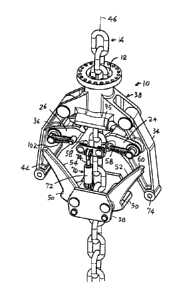
A chain connector for holding a chain (14) that moors a vessel to the sea floor under perhaps 2000 tons tension, which can be quickly disconnected in an emergency by applying a moderate disconnecting force such as 50 tons. The chain is held by ratchets (24, 26) that are mounted on arms (34, 36). The arms have upper ends (35) that are pivotally mounted on a housing (38) and have free lower ends (44), with the lower ends being held by cams (50) on locking dogs (52) that have locking dog lower ends (51) pivotally mounted on the housing and free upper ends (60). A hydraulic actuator (70) has pins (58) that engage the upper ends of the locking dogs to prevent the arms and dogs from pivoting apart until the locking dog upper ends (60) are raised.


French Abstract

Connecteur de chaîne servant à maintenir une chaîne (14) pouvant amarrer un vaisseau jusqu'au fond de la mer sous éventuellement 2 000 tonnes de tension, qui peut être rapidement déconnecté en cas d'urgence par l'application d'une force de déconnexion modérée, par exemple 50 tonnes. La chaîne est maintenue par des rochets (24, 26) qui sont montés sur des bras (34, 36). Les bras ont des extrémités supérieures (35) qui sont montées de manière pivotante sur un logement (38) et ont des extrémités inférieures libres (44), maintenues par des cames (50) sur des griffes de blocage (52) dont les extrémités inférieures (51) sont montées de manière pivotante sur le logement et dont les extrémités supérieures (60) sont libres. Un actionneur hydraulique (70) possède des axes (58) qui viennent en prise avec les extrémités supérieures des griffes de verrouillage pour empêcher l'écart de pivotement entre les bras et les griffes jusqu'à ce que les extrémités supérieures de la griffe de blocage (60) soient levées.

Claims

Note: Claims are shown in the official language in which they were submitted.


-5-

WHAT IS CLAIMED IS:

1. A chain connector comprising:
a housing (36) that has at least a partially vertical chain passage (12)
through which a chain extends;
a pair of arms (34, 36) each having an upper end (34) pivotally mounted on
said housing about a different arm axis (40, 42), each arm having a lower end
(44);
a pair of ratchets (24, 26) each coupled to one of said arms, said ratchets
each being engageable with said chain to support the chain and each ratchet
being
disengageable from said chain to release it;
a pair of locking dogs (52), each having a lower end (44) pivotally mounted
on said housing and each dog having a free upper end (60), each dog forming a
cam (50) that engages the lower end of one of said arms so when the dog upper
ends are released to move apart they release the arm lower ends to move apart;
an activation device (70) mounted on said housing, said device having a pair
of pins (58) that each engages one of said locking dog upper ends to prevent
said
locking dog upper ends from pivoting apart, said activation device being
moveable
to release said locking dog upper ends.
2. The chain connector described in claim 1 wherein:
said body has a center plane (90) and said locking dogs move in said center
plane when said dogs pivot, and said chain has alternate aligned links (92)
and
perpendicular links (95);
a portion of said chain that lies in said chain passage has aligned links that

lie in said center plane;
each of said ratchets has a concave chain-engaging surface (94) that is
curved to make area contact with the lower end of one of said aligned links.
3. The chain connector described in claim 1 wherein:
said activation device includes a hydraulic cylinder (72) mounted on said
housing below the height of said locking dog free upper ends, and a piston
(74)
having a lower portion lying in said cylinder and a vertically slideable upper
end,


-6-
said piston upper end carrying a pair of pins (58) that each lies against one
of said
dog upper ends (60) when said locking dogs are not pivoted apart, to prevent
said
locking dogs from pivoting apart until said pins are raised.

Description

Note: Descriptions are shown in the official language in which they were submitted.


CA 02865128 2014-08-20
WO 2013/124717
PCT/1B2013/000082
CHAIN CONNECTOR
BACKGROUND OF THE INVENTION
A vessel or other floating body is commonly moored to the sea floor by a
chain that passes though a chain connector on the floating body and down to
the
sea floor. Although a few chains may be used to moor the vessel, the tension
in
each chain may be very high, such as 2000 tons. Previously, tension in the
chain
had to be reduced before the chain could be disconnected, and large forces
were
required. The force required to disconnect the chain while it is under
tension,
should be moderate. Also, the chain connector should be of moderate size. A
chain connector of moderate size that allowed emergency disconnection of a
chain
using only a moderate force, such as no more than 5% of the chain tension for
the
disconnection, would be of value.
SUMMARY OF THE INVENTION
In accordance with one embodiment of the invention, a chain connector is
provided that holds a chain that may be subjected to a very high tension such
as
2000 tons, and that allows the chain to be disconnected from a floating body
or the
like by applying only a moderate release force such 50 tons. The chain extends
though a housing and one of its chain links is supported by ratchets. The
ratchets
are mounted on first levers in the form of arms that have upper ends pivotally

connected to the chain connector housing and that have free lower ends. The
chain connector also has a pair of second levers, or locking dogs, that have
lower
ends forming cams that hold or release the arm lower ends. The locking dogs
have
upper ends that are held together by pins. When the pins are raised, they
release
the locking dog upper ends. This allows the locking dog upper ends to move
apart,
so the cams on the locking dog lower ends release the arms to pivot apart and
release the ratchets to release the chain.
The ratchets are pivotally supported on the arms. The ratchets have
concave upper ends that receive the convex lower ends of alternate chain
links, to
distribute the load.
The novel features of the invention are set forth with particularity in the

CA 02865128 2014-08-20
WO 2013/124717
PCT/1B2013/000082
-2-
appended claims. The invention will be best understood from the following
description when read in conjunction with the accompanying drawings.
BRIEF DESCRIPTION OF THE DRAWINGS
Fig. 1 is an isometric view of a chain connector, with an unsupported chain
extending though a passage therein.
Fig. 2 is an isometric view of the chain connector of Fig. 1, with an upper
part
of the housing removed for clarity and with the chain supported.
Fig. 3 is a sectional side view of the chain connector of Fig. 1 with the left
side of Fig. 3 taken on a centerline of the connector and the right side taken
from
in front of the locking dogs.
Fig. 4 is a front elevation view of the chain connector of Fig. 3.
Fig. 5 is a side view of the chain connector of Fig. 4.
DESCRIPTION OF THE PREFERRED EMBODIMENTS
Fig. 1 shows a chain connector 10 of the invention, which has a passage 12
though which a chain 14 usually extends. The chain connector 10 is usually
mounted on a floating body such as a vessel, with the chain extending down to
the
sea floor and anchored thereat to limit drift of the vessel. However, the
chain is
useful in a variety of applications. Occasionally , the chain must be
disconnected
from the chain connector, as to allow the replacement of a mooring leg,
maintenance, or to allow the vessel to drift or sail away from its moored
location.
In that case, the chain may be under a high tension such as 2000 tons. The
present chain connector is designed to disconnect the tensioned chain from the
chain connector using only a moderate force such as 10% of the chain tension
for
a chain connector of moderate length.
Fig. 3 shows that the chain is supported by upper ends 22 of ratchets 24, 26.
The ratchets are pivotally mounted about axes 30, 32 on arms 34, 36, The arms
have upper ends 35 pivotally mounted on the chain connector housing 38, about
axes 40, 42. The arms have lower ends 44 that are prevented from moving away
from a connector axis 46 by cams 50 that are formed on locking dogs 52, 54
(Fig.
1). The locking dogs each has a lower end that forms a cam 50 and has an upper

CA 02865128 2014-08-20
WO 2013/124717
PCT/1B2013/000082
-3-
end 60. When a pin 56,58 is moved up and away from the upper ends 60 of the
locking dogs, then the locking dog upper ends are free to move apart, to the
positions shown in Fig. 1. As the locking dogs move apart, their cams 50
release
the arms 34, 36 and the arms also move apart. Movement of the arms away from
each other, to the position of Fig. 1, moves the ratchets 24, 26 away from the
chain
so the chain is free to move down though the housing passage 12.
The disconnection process is performed by energizing an activating device,
preferably an hydraulic jack 70 (Fig. 1) which has a cylinder 72 mounted on
the
housing and a piston 74 that can be forcefully moved up. The upper end of the
piston holds two pins 58. As shown in Fig. 3, each pin 58, lies against the
upper
end 60 of one of the locking dogs 52, 54.
The combinations of arms and locking dogs enable the chain to be released
by using only a moderate force such as an upward force of 50 tons applied by
the
jack 70. Instead of using the arms 34,36 combined with the locking dogs 52,
54,
it would be possible to use very long arms. However, it is important to
minimize the
size of the chain connector and the presence of the locking dogs limits the
height
of the chain connector. The fact that the chain can be released while under
high
tension allows a release without first reducing chain tension.
The housing has a center plane 90 (Fig. 5) and the chain has aligned links
such as 92 that are widest along the center plane and has alternate
perpendicular
links such as 94 that are widest along a plane that is perpendicular to the
center
plane. The ratchets (Fig. 3) have concave upper faces 95 that are curved about
two
axes to distribute the downward force of a chain link over a wide area. The
ratchets
engage only the aligned links 92. The ratchets are pivoted to move against and
away from the chain by the aligned chain links 92 pushing below the ratchets
when
pulling on the chain. Levers 102 that engage housing surface 104, are
pivotally
mounted on the arms and help control arm position.
Thus, the invention provides a chain connector that enables its
disconnection from a chain that is under a high tension (on the order of
magnitude
of 2000 tons), by applying only a moderate force that is less than 10% and
preferably less than 5% of the chain tension. The chain connector includes
ratchets mounted on arms that have upper ends pivotally mounted on the control

CA 02865128 2014-08-20
WO 2013/124717
PCT/1B2013/000082
-4-
housing. The lower ends of the arms are held against pivoting apart by cams
that
are located on locking dogs. The locking dogs have upper ends that are held
close
to the housing axis by pins on a jack. The jack can be operated to raise the
pins
out of engagement with the locking dogs to allow the arms and dogs to pivot
apart
and thereby release the chain.
Thus, the invention provides a chain connector of moderate size, which can
disconnect from a chain while the chain is under high tension. The connector
includes arms with upper ends that are pivotally mounted on the housing and
with
free lower arm ends. The connector also includes locking dogs with lower ends
that
are pivotally mounted on the housing and with free upper ends. The lower ends
of
the locking dogs form cams that release the arm free lower ends to pivot apart

when the dog upper ends are released to move apart. Ratchets that engage the
links have upper faces that are curved about two perpendicular axes to provide

large area engagement with the links.
Although particular embodiments of the invention have been described and
illustrated herein, it is recognized that modifications and variations may
readily
occur to those skilled in the art, and consequently, it is intended that the
claims be
interpreted to cover such modifications and equivalents.

Representative Drawing
A single figure which represents the drawing illustrating the invention.
Administrative Status

For a clearer understanding of the status of the application/patent presented on this page, the site Disclaimer , as well as the definitions for Patent , Administrative Status , Maintenance Fee  and Payment History  should be consulted.

Administrative Status

Title Date
Forecasted Issue Date 2019-07-02
(86) PCT Filing Date 2013-01-23
(87) PCT Publication Date 2013-08-29
(85) National Entry 2014-08-20
Examination Requested 2018-01-05
(45) Issued 2019-07-02
Deemed Expired 2021-01-25

Abandonment History

There is no abandonment history.

Payment History

Fee Type Anniversary Year Due Date Amount Paid Paid Date
Application Fee $400.00 2014-08-20
Maintenance Fee - Application - New Act 2 2015-01-23 $100.00 2014-08-20
Registration of a document - section 124 $100.00 2014-10-17
Maintenance Fee - Application - New Act 3 2016-01-25 $100.00 2015-12-17
Maintenance Fee - Application - New Act 4 2017-01-23 $100.00 2017-01-09
Request for Examination $800.00 2018-01-05
Maintenance Fee - Application - New Act 5 2018-01-23 $200.00 2018-01-09
Maintenance Fee - Application - New Act 6 2019-01-23 $200.00 2019-01-08
Final Fee $300.00 2019-05-15
Maintenance Fee - Patent - New Act 7 2020-01-23 $200.00 2020-01-03
Owners on Record

Note: Records showing the ownership history in alphabetical order.

Current Owners on Record
SINGLE BUOY MOORINGS, INC.
Past Owners on Record
None
Past Owners that do not appear in the "Owners on Record" listing will appear in other documentation within the application.
Documents

To view selected files, please enter reCAPTCHA code :


To view images, click a link in the Document Description column. To download the documents, select one or more checkboxes in the first column and then click the "Download Selected in PDF format (Zip Archive)" or the "Download Selected as Single PDF" button.

List of published and non-published patent-specific documents on the CPD .

If you have any difficulty accessing content, you can call the Client Service Centre at 1-866-997-1936 or send them an e-mail at CIPO Client Service Centre.


Document
Description 
Date
(yyyy-mm-dd) 
Number of pages   Size of Image (KB) 
Abstract 2014-08-20 2 72
Claims 2014-08-20 2 55
Drawings 2014-08-20 2 72
Description 2014-08-20 4 195
Representative Drawing 2014-08-20 1 24
Cover Page 2015-01-27 2 50
Request for Examination 2018-01-05 2 45
Final Fee 2019-05-15 2 52
Representative Drawing 2019-06-03 1 11
Cover Page 2019-06-03 1 44
PCT 2014-08-20 2 50
Assignment 2014-08-20 6 188
Correspondence 2014-10-17 2 80
Assignment 2014-10-17 4 117