Language selection

Search

Patent 2875043 Summary

Third-party information liability

Some of the information on this Web page has been provided by external sources. The Government of Canada is not responsible for the accuracy, reliability or currency of the information supplied by external sources. Users wishing to rely upon this information should consult directly with the source of the information. Content provided by external sources is not subject to official languages, privacy and accessibility requirements.

Claims and Abstract availability

Any discrepancies in the text and image of the Claims and Abstract are due to differing posting times. Text of the Claims and Abstract are posted:

  • At the time the application is open to public inspection;
  • At the time of issue of the patent (grant).
(12) Patent: (11) CA 2875043
(54) English Title: HEATING CABLES
(54) French Title: CABLES CHAUFFANTS
Status: Granted
Bibliographic Data
(51) International Patent Classification (IPC):
  • H05B 3/58 (2006.01)
  • F16L 53/38 (2018.01)
(72) Inventors :
  • HEISE, LORNE R. (Canada)
  • MYERS, CHUCK H. (United States of America)
(73) Owners :
  • HEAT-LINE CORPORATION (Canada)
(71) Applicants :
  • HEAT-LINE CORPORATION (Canada)
(74) Agent: BLAKE, CASSELS & GRAYDON LLP
(74) Associate agent:
(45) Issued: 2019-08-20
(22) Filed Date: 2014-12-12
(41) Open to Public Inspection: 2015-06-12
Examination requested: 2019-06-12
Availability of licence: N/A
(25) Language of filing: English

Patent Cooperation Treaty (PCT): No

(30) Application Priority Data:
Application No. Country/Territory Date
61/915,335 United States of America 2013-12-12

Abstracts

English Abstract

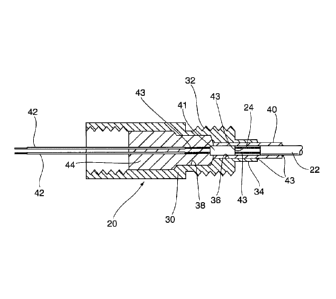
A heating assembly for use in a fluid line has a heating cable including electrical resistance wires encapsulated in a metal sheath. The cable passes through a fitting where it is connected to a power supply. The connection between the power supply and the heating cable is encapsulated within the fitting, and the metal sheath is secured to the fitting with a permanent connection. A bushing is provided to support the connection between the resistance wires and the power supply within the fitting. The elongate sheath may be inserted into a fluid line and the fitting connected to that line using a mechanical connection.


French Abstract

Ensemble de chauffage conçu pour être utilisé dans une conduite liquide et présentant un câble chauffant comportant des câbles à résistance électrique encapsulés dans une gaine de métal. Le câble passe par un accessoire, où il est raccordé à une alimentation. La connexion entre lalimentation et le câble chauffant est encapsulée dans laccessoire et la gaine de métal est fixée à laccessoire par un raccord permanent. Une bague est prévue pour maintenir la connexion entre les câbles de résistance et lalimentation, dans laccessoire. La gaine allongée peut être insérée dans une conduite liquide et laccessoire raccordé à cette conduite par une connexion mécanique.

Claims

Note: Claims are shown in the official language in which they were submitted.


Claims
1. A heater assembly for use in a fluid line, said assembly including a
fitting for connection
to said fluid line, a heating cable secured to said fitting and including an
electrical resistance wire
encapsulated in a sheath, a power cable to supply electrical power to said
resistance wire, a
bushing located in a bore in said fitting, said sheath being received in said
bushing and a
connection between said power cable and said resistance wire being located
within said bushing,
said bushing being secured to said fitting and to said sheath to establish a
connection between
said fitting and said sheath, said power cable being connected to said
resistance wire through a
spacer located in said bushing and spaced from said sheath, said spacer having
intermediate
wires extending therethrough, with said resistance wires connected to said
intermediate wires on
one side of said bushing and said power supply connected to said intermediate
wires on the
opposite side of said spacer.
2. A heater assembly according to claim 1 wherein said connection of said
power supply to
said intermediate wire is located within said fitting.
3. A heater assembly according to claim 2 wherein said fitting has a
counterbore and said
connection of said power supply to said intermediate wire is located in said
counterbore.
4. A heater assembly according to claim 3 wherein said counterbore is
filled with a curable
filler to encapsulate said connection.
5. A heater assembly according to any one of claims 1 to 4, wherein said
intermediate wires
are of greater diameter than said resistance wires.
6. A heater assembly according to any one of claims 1 to 5, wherein said
bushing is
connected to said fitting and to said sheath at spaced locations.
7. A heater assembly according to any one of claims 1 to 6, wherein said
sheath is metal.
-6-

Description

Note: Descriptions are shown in the official language in which they were submitted.


HEATING CABLES
FIELD OF THE INVENTION
[0001] The present invention relates to heaters for heating fluid lines
such as oil lines,
hydraulic lines, and the like.
[0002] One of the challenges facing the operation of machinery in low
temperature
environments is the significant increase of viscosity of fluid, such as oil,
within the machine
when it is left unused.
[0003] Starting the machine in a cold state may result in starving of the
flow of lubricating
oils through the machine due to its increased viscosity that may lead to rapid
deterioration and
failure of the machine.
[0004] It is known to provide heating blankets and the like over such
machines but these are
relatively energy intensive as they are attempting to maintain the whole
machine at an elevated
temperature, rather than specific areas of the machine.
[0005] Mineral filled heating cables have a pair of resistance wires within
a metal outer
sheath with a mineral powder filling to insulate the wires from the sheath.
They can therefore be
used to provide localised heating to the exterior of machines, but again this
is relatively
inefficient due to the heat loss to the surroundings. The cables are also
vulnerable when used
externally, making their use in arduous conditions difficult.
100061 Self-regulating heating cables, that is heating cables which
regulate the current
supplied to the heating cable in proportion to the ambient conditions, are
used with water supply
pipes as a freeze prevention device. The heat loss to the surrounding
environment is mitigated
and the supply pipe may be insulated if appropriate. Such cables however are
intended for low
-2-
22654803.2
CA 2875043 2019-06-12

CA 02875043 2014-12-12
pressure applications and can operate in a relatively restricted temperature
range. A maximum
operating temperature of 185 . F is typical for such cables, which is too low
for many machinery
applications.
[0007] Mineral insulated heating cables are capable of operating
temperatures up to 1000.F
are mechanically robust enough to withstand elevated operating pressures.
However, when used
with low voltage sources, such as those typically found in mobile machinery
applications, the
resistance wires are of very small diameter and therefore fragile, requiring
protection if they are
to be used in the robust operating conditions required for many machine
applications.
[0008] It is therefore an object of the present invention to obviate or
mitigate the above
disadvantages.
SUMMARY OF THE INVENTION
[0009] According to the present invention there is provided a heating cable
for use in a fluid
line including electrical resistance wires encapsulated in a metal sheath. The
cable passes
through a fitting where it is connected to a power supply. The connection
between the power
supply and the heating cable is encapsulated within the fitting, and the metal
sheath is secured to
the fitting with a permanent connection. The elongate sheath may be inserted
into a fluid line
and the fitting connected to that line using a mechanical connection.
BRIEF DESCRIPTION OF THE DRAWINGS
[0010] Embodiments of the invention will now be described by way of example
only with
reference to the accompanying drawings in which:
[0011] FIG. 1 is a schematic representation of an earth moving machine;
[0012] FIG. 2 is a section on the line 1141 of Figure 1; and
[0013] FIG. 3 is a schematic representation of the assembly of the
components of the heating
cable shown in Figure 2.
-3-
22654803.1

CA 02875043 2014-12-12
[0014] Referring therefore to Figure 1, an earth moving machine 10 has an
engine 12 and an
oil supply conduit 14 that runs external of the vehicle. The oil conduit 14
may convey oil from a
reservoir to the engine or to a pump driven by the engine, and may be either a
flexible conduit or
a rigid metal conduit depending upon the particular application. To avoid an
unacceptable
increase in the viscosity of oil carried by conduit 12, a heater assembly 20
is inserted into the
conduit 14 to maintain the fluid at an elevated temperature.
[0015] The heater assembly 20 may be seen in greater detail in Figures 2
and 3. The heater
assembly 20 includes a heating cable 22 that has a pair of heater wires 24 and
an outer steel
sheath 26. An insulating powder, such as magnesium oxide is located in the
sheath 26 to prevent
contact between the wires and the sheath. The end of the tube 26 is sealed
with an end seal 28 to
inhibit ingress of oil within the tube 26. The sheath 26 is malleable so it
may adapt to the
configuration of the conduit 12. Typically, the sheath 26 is made from
stainless steel or a
material with similar physical properties.
[0016] The heater assembly 20 includes a fitting 30 having an external
threaded boss 32
which conveniently is of a standard pipe thread form such as a JIC Fitting.
The boss 32 has an
extended nose 34 with a pilot hole 36 extending along the axis of the fitting
through the nose 34.
The pilot hole extends into a counter bore 38 in the fitting 30.
[0017] The pilot hole 36 is dimensioned to receive an annular bushing 40
whose internal
diameter corresponds to the external diameter of the metal sheath 26. A spacer
41 is located in
the bushing 40 adjacent the counter bore 38 to provide a void between the
sheath 26 and the
spacer. Intermediate wires 43 extend through and to both sides of the spacer
41 and are
connected in the void to the wires 24 of the heater cable 22. The wires 43 are
connected on the
opposite side to power supply wires 42. It is convenient for the spacer 41 to
be formed from a
short section of mineral insulated heating cable having larger diameter wires
than the wires 24 of
the cable 22.
[0018] As can be best seen in Figure 3, the heater assembly 20 is assembled
by initially
connecting the wires 42 to the heater wires 24 by crimping to the wires 43 on
either side of the
spacer 41. The bushing 40 is slid on to the sheath 26 and positioned over the
splice between the
-4--
22654803.1

CA 02875043 2014-12-12
wires 43 and 24. In this position, as seen in Fig 2, the sheath 26 and spacer
41 is located within
the bushing 40, with the connection of the wires 43 to the power supply line
outside the bushing
40: The fitting 30 is then slid over the wires 42 until the bushing 40 is
located in the pilot hole
36 with the spacer 41 adjacent to the counterbore 38. In this position, the
connection of the wires
43 to the power cable 42 is within the counterbore 38. The bushing 40 is
silver soldered or
welded to the nose 34 and also silver soldered or welded to the sheathing 26
to provide a
permanent connection between the fitting and the sheathing.
[0019] With the sheathing 26 secured to the fitting 30, the splices remain
in the void and in
the counter bore 38. The counterbore 38 is then filled with an epoxy 44 to
maintain the heater
cables separated and insulated.
[0020] To use the heater cable, a threaded fitting, such as a T, is
provided in the duct 12.
The metal sheath 26 is fed through the access port provided by one branch of
the T and along the
duct until the fitting 30 can be threaded into the access port. In this
configuration, the cable
extends along the duct within the hydraulic fluid or oil that will be
contained in the duct.
[0021] The heater wires 24 are then connected to a low voltage, typically
24 volt power
source, to provide energy to the heater cable to maintain the temperature of
the oil within the
duct.
[0022] The use of the spacer 41 permits larger diameter conductors to be
used for connection
to the power supply 42 and the bushing 40 provides a mechanical support within
the fitting 36
for the connection to the resistance wires 24 of the cable 22. The bushing
also provides spaced
connections for the attachment to the fitting and the sheath, allowing welding
or silver soldering
to be performed in a convenient manner.
-5-
22654803.1

Representative Drawing
A single figure which represents the drawing illustrating the invention.
Administrative Status

For a clearer understanding of the status of the application/patent presented on this page, the site Disclaimer , as well as the definitions for Patent , Administrative Status , Maintenance Fee  and Payment History  should be consulted.

Administrative Status

Title Date
Forecasted Issue Date 2019-08-20
(22) Filed 2014-12-12
(41) Open to Public Inspection 2015-06-12
Examination Requested 2019-06-12
(45) Issued 2019-08-20

Abandonment History

There is no abandonment history.

Maintenance Fee

Last Payment of $210.51 was received on 2023-11-10


 Upcoming maintenance fee amounts

Description Date Amount
Next Payment if standard fee 2024-12-12 $347.00
Next Payment if small entity fee 2024-12-12 $125.00

Note : If the full payment has not been received on or before the date indicated, a further fee may be required which may be one of the following

  • the reinstatement fee;
  • the late payment fee; or
  • additional fee to reverse deemed expiry.

Patent fees are adjusted on the 1st of January every year. The amounts above are the current amounts if received by December 31 of the current year.
Please refer to the CIPO Patent Fees web page to see all current fee amounts.

Payment History

Fee Type Anniversary Year Due Date Amount Paid Paid Date
Registration of a document - section 124 $100.00 2014-12-12
Application Fee $400.00 2014-12-12
Maintenance Fee - Application - New Act 2 2016-12-12 $100.00 2016-09-09
Maintenance Fee - Application - New Act 3 2017-12-12 $100.00 2017-09-13
Maintenance Fee - Application - New Act 4 2018-12-12 $100.00 2018-09-10
Request for Examination $800.00 2019-06-12
Final Fee $300.00 2019-07-05
Maintenance Fee - Patent - New Act 5 2019-12-12 $200.00 2019-10-08
Maintenance Fee - Patent - New Act 6 2020-12-14 $200.00 2020-11-26
Maintenance Fee - Patent - New Act 7 2021-12-13 $204.00 2021-09-16
Maintenance Fee - Patent - New Act 8 2022-12-12 $203.59 2022-09-23
Maintenance Fee - Patent - New Act 9 2023-12-12 $210.51 2023-11-10
Owners on Record

Note: Records showing the ownership history in alphabetical order.

Current Owners on Record
HEAT-LINE CORPORATION
Past Owners on Record
None
Past Owners that do not appear in the "Owners on Record" listing will appear in other documentation within the application.
Documents

To view selected files, please enter reCAPTCHA code :


To view images, click a link in the Document Description column. To download the documents, select one or more checkboxes in the first column and then click the "Download Selected in PDF format (Zip Archive)" or the "Download Selected as Single PDF" button.

List of published and non-published patent-specific documents on the CPD .

If you have any difficulty accessing content, you can call the Client Service Centre at 1-866-997-1936 or send them an e-mail at CIPO Client Service Centre.


Document
Description 
Date
(yyyy-mm-dd) 
Number of pages   Size of Image (KB) 
Maintenance Fee Payment 2022-09-23 1 33
Abstract 2014-12-12 1 15
Description 2014-12-12 4 166
Claims 2014-12-12 2 42
Drawings 2014-12-12 3 167
Representative Drawing 2015-05-20 1 33
Cover Page 2015-06-23 1 61
Maintenance Fee Payment 2018-09-10 1 33
Request for Examination / PPH Request / Amendment 2019-06-12 13 402
Description 2019-06-12 4 166
Claims 2019-06-12 1 40
Drawings 2019-06-12 3 41
Amendment after Allowance 2019-06-19 4 110
Claims 2019-06-19 1 41
Final Fee 2019-07-05 4 98
Assignment 2014-12-12 10 327
Representative Drawing 2019-07-23 1 6
Cover Page 2019-07-23 1 33
Maintenance Fee Payment 2023-11-10 1 33