Sélection de la langue

Search

Sommaire du brevet 2875043 

Énoncé de désistement de responsabilité concernant l'information provenant de tiers

Une partie des informations de ce site Web a été fournie par des sources externes. Le gouvernement du Canada n'assume aucune responsabilité concernant la précision, l'actualité ou la fiabilité des informations fournies par les sources externes. Les utilisateurs qui désirent employer cette information devraient consulter directement la source des informations. Le contenu fourni par les sources externes n'est pas assujetti aux exigences sur les langues officielles, la protection des renseignements personnels et l'accessibilité.

Disponibilité de l'Abrégé et des Revendications

L'apparition de différences dans le texte et l'image des Revendications et de l'Abrégé dépend du moment auquel le document est publié. Les textes des Revendications et de l'Abrégé sont affichés :

  • lorsque la demande peut être examinée par le public;
  • lorsque le brevet est émis (délivrance).
(12) Brevet: (11) CA 2875043
(54) Titre français: CABLES CHAUFFANTS
(54) Titre anglais: HEATING CABLES
Statut: Octroyé
Données bibliographiques
(51) Classification internationale des brevets (CIB):
  • H05B 3/58 (2006.01)
  • F16L 53/38 (2018.01)
(72) Inventeurs :
  • HEISE, LORNE R. (Canada)
  • MYERS, CHUCK H. (Etats-Unis d'Amérique)
(73) Titulaires :
  • HEAT-LINE CORPORATION (Canada)
(71) Demandeurs :
  • HEAT-LINE CORPORATION (Canada)
(74) Agent: BLAKE, CASSELS & GRAYDON LLP
(74) Co-agent:
(45) Délivré: 2019-08-20
(22) Date de dépôt: 2014-12-12
(41) Mise à la disponibilité du public: 2015-06-12
Requête d'examen: 2019-06-12
Licence disponible: S.O.
(25) Langue des documents déposés: Anglais

Traité de coopération en matière de brevets (PCT): Non

(30) Données de priorité de la demande:
Numéro de la demande Pays / territoire Date
61/915,335 Etats-Unis d'Amérique 2013-12-12

Abrégés

Abrégé français

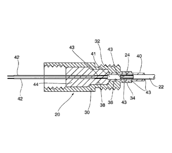
Ensemble de chauffage conçu pour être utilisé dans une conduite liquide et présentant un câble chauffant comportant des câbles à résistance électrique encapsulés dans une gaine de métal. Le câble passe par un accessoire, où il est raccordé à une alimentation. La connexion entre lalimentation et le câble chauffant est encapsulée dans laccessoire et la gaine de métal est fixée à laccessoire par un raccord permanent. Une bague est prévue pour maintenir la connexion entre les câbles de résistance et lalimentation, dans laccessoire. La gaine allongée peut être insérée dans une conduite liquide et laccessoire raccordé à cette conduite par une connexion mécanique.


Abrégé anglais

A heating assembly for use in a fluid line has a heating cable including electrical resistance wires encapsulated in a metal sheath. The cable passes through a fitting where it is connected to a power supply. The connection between the power supply and the heating cable is encapsulated within the fitting, and the metal sheath is secured to the fitting with a permanent connection. A bushing is provided to support the connection between the resistance wires and the power supply within the fitting. The elongate sheath may be inserted into a fluid line and the fitting connected to that line using a mechanical connection.

Revendications

Note : Les revendications sont présentées dans la langue officielle dans laquelle elles ont été soumises.


Claims
1. A heater assembly for use in a fluid line, said assembly including a
fitting for connection
to said fluid line, a heating cable secured to said fitting and including an
electrical resistance wire
encapsulated in a sheath, a power cable to supply electrical power to said
resistance wire, a
bushing located in a bore in said fitting, said sheath being received in said
bushing and a
connection between said power cable and said resistance wire being located
within said bushing,
said bushing being secured to said fitting and to said sheath to establish a
connection between
said fitting and said sheath, said power cable being connected to said
resistance wire through a
spacer located in said bushing and spaced from said sheath, said spacer having
intermediate
wires extending therethrough, with said resistance wires connected to said
intermediate wires on
one side of said bushing and said power supply connected to said intermediate
wires on the
opposite side of said spacer.
2. A heater assembly according to claim 1 wherein said connection of said
power supply to
said intermediate wire is located within said fitting.
3. A heater assembly according to claim 2 wherein said fitting has a
counterbore and said
connection of said power supply to said intermediate wire is located in said
counterbore.
4. A heater assembly according to claim 3 wherein said counterbore is
filled with a curable
filler to encapsulate said connection.
5. A heater assembly according to any one of claims 1 to 4, wherein said
intermediate wires
are of greater diameter than said resistance wires.
6. A heater assembly according to any one of claims 1 to 5, wherein said
bushing is
connected to said fitting and to said sheath at spaced locations.
7. A heater assembly according to any one of claims 1 to 6, wherein said
sheath is metal.
-6-

Description

Note : Les descriptions sont présentées dans la langue officielle dans laquelle elles ont été soumises.


HEATING CABLES
FIELD OF THE INVENTION
[0001] The present invention relates to heaters for heating fluid lines
such as oil lines,
hydraulic lines, and the like.
[0002] One of the challenges facing the operation of machinery in low
temperature
environments is the significant increase of viscosity of fluid, such as oil,
within the machine
when it is left unused.
[0003] Starting the machine in a cold state may result in starving of the
flow of lubricating
oils through the machine due to its increased viscosity that may lead to rapid
deterioration and
failure of the machine.
[0004] It is known to provide heating blankets and the like over such
machines but these are
relatively energy intensive as they are attempting to maintain the whole
machine at an elevated
temperature, rather than specific areas of the machine.
[0005] Mineral filled heating cables have a pair of resistance wires within
a metal outer
sheath with a mineral powder filling to insulate the wires from the sheath.
They can therefore be
used to provide localised heating to the exterior of machines, but again this
is relatively
inefficient due to the heat loss to the surroundings. The cables are also
vulnerable when used
externally, making their use in arduous conditions difficult.
100061 Self-regulating heating cables, that is heating cables which
regulate the current
supplied to the heating cable in proportion to the ambient conditions, are
used with water supply
pipes as a freeze prevention device. The heat loss to the surrounding
environment is mitigated
and the supply pipe may be insulated if appropriate. Such cables however are
intended for low
-2-
22654803.2
CA 2875043 2019-06-12

CA 02875043 2014-12-12
pressure applications and can operate in a relatively restricted temperature
range. A maximum
operating temperature of 185 . F is typical for such cables, which is too low
for many machinery
applications.
[0007] Mineral insulated heating cables are capable of operating
temperatures up to 1000.F
are mechanically robust enough to withstand elevated operating pressures.
However, when used
with low voltage sources, such as those typically found in mobile machinery
applications, the
resistance wires are of very small diameter and therefore fragile, requiring
protection if they are
to be used in the robust operating conditions required for many machine
applications.
[0008] It is therefore an object of the present invention to obviate or
mitigate the above
disadvantages.
SUMMARY OF THE INVENTION
[0009] According to the present invention there is provided a heating cable
for use in a fluid
line including electrical resistance wires encapsulated in a metal sheath. The
cable passes
through a fitting where it is connected to a power supply. The connection
between the power
supply and the heating cable is encapsulated within the fitting, and the metal
sheath is secured to
the fitting with a permanent connection. The elongate sheath may be inserted
into a fluid line
and the fitting connected to that line using a mechanical connection.
BRIEF DESCRIPTION OF THE DRAWINGS
[0010] Embodiments of the invention will now be described by way of example
only with
reference to the accompanying drawings in which:
[0011] FIG. 1 is a schematic representation of an earth moving machine;
[0012] FIG. 2 is a section on the line 1141 of Figure 1; and
[0013] FIG. 3 is a schematic representation of the assembly of the
components of the heating
cable shown in Figure 2.
-3-
22654803.1

CA 02875043 2014-12-12
[0014] Referring therefore to Figure 1, an earth moving machine 10 has an
engine 12 and an
oil supply conduit 14 that runs external of the vehicle. The oil conduit 14
may convey oil from a
reservoir to the engine or to a pump driven by the engine, and may be either a
flexible conduit or
a rigid metal conduit depending upon the particular application. To avoid an
unacceptable
increase in the viscosity of oil carried by conduit 12, a heater assembly 20
is inserted into the
conduit 14 to maintain the fluid at an elevated temperature.
[0015] The heater assembly 20 may be seen in greater detail in Figures 2
and 3. The heater
assembly 20 includes a heating cable 22 that has a pair of heater wires 24 and
an outer steel
sheath 26. An insulating powder, such as magnesium oxide is located in the
sheath 26 to prevent
contact between the wires and the sheath. The end of the tube 26 is sealed
with an end seal 28 to
inhibit ingress of oil within the tube 26. The sheath 26 is malleable so it
may adapt to the
configuration of the conduit 12. Typically, the sheath 26 is made from
stainless steel or a
material with similar physical properties.
[0016] The heater assembly 20 includes a fitting 30 having an external
threaded boss 32
which conveniently is of a standard pipe thread form such as a JIC Fitting.
The boss 32 has an
extended nose 34 with a pilot hole 36 extending along the axis of the fitting
through the nose 34.
The pilot hole extends into a counter bore 38 in the fitting 30.
[0017] The pilot hole 36 is dimensioned to receive an annular bushing 40
whose internal
diameter corresponds to the external diameter of the metal sheath 26. A spacer
41 is located in
the bushing 40 adjacent the counter bore 38 to provide a void between the
sheath 26 and the
spacer. Intermediate wires 43 extend through and to both sides of the spacer
41 and are
connected in the void to the wires 24 of the heater cable 22. The wires 43 are
connected on the
opposite side to power supply wires 42. It is convenient for the spacer 41 to
be formed from a
short section of mineral insulated heating cable having larger diameter wires
than the wires 24 of
the cable 22.
[0018] As can be best seen in Figure 3, the heater assembly 20 is assembled
by initially
connecting the wires 42 to the heater wires 24 by crimping to the wires 43 on
either side of the
spacer 41. The bushing 40 is slid on to the sheath 26 and positioned over the
splice between the
-4--
22654803.1

CA 02875043 2014-12-12
wires 43 and 24. In this position, as seen in Fig 2, the sheath 26 and spacer
41 is located within
the bushing 40, with the connection of the wires 43 to the power supply line
outside the bushing
40: The fitting 30 is then slid over the wires 42 until the bushing 40 is
located in the pilot hole
36 with the spacer 41 adjacent to the counterbore 38. In this position, the
connection of the wires
43 to the power cable 42 is within the counterbore 38. The bushing 40 is
silver soldered or
welded to the nose 34 and also silver soldered or welded to the sheathing 26
to provide a
permanent connection between the fitting and the sheathing.
[0019] With the sheathing 26 secured to the fitting 30, the splices remain
in the void and in
the counter bore 38. The counterbore 38 is then filled with an epoxy 44 to
maintain the heater
cables separated and insulated.
[0020] To use the heater cable, a threaded fitting, such as a T, is
provided in the duct 12.
The metal sheath 26 is fed through the access port provided by one branch of
the T and along the
duct until the fitting 30 can be threaded into the access port. In this
configuration, the cable
extends along the duct within the hydraulic fluid or oil that will be
contained in the duct.
[0021] The heater wires 24 are then connected to a low voltage, typically
24 volt power
source, to provide energy to the heater cable to maintain the temperature of
the oil within the
duct.
[0022] The use of the spacer 41 permits larger diameter conductors to be
used for connection
to the power supply 42 and the bushing 40 provides a mechanical support within
the fitting 36
for the connection to the resistance wires 24 of the cable 22. The bushing
also provides spaced
connections for the attachment to the fitting and the sheath, allowing welding
or silver soldering
to be performed in a convenient manner.
-5-
22654803.1

Dessin représentatif
Une figure unique qui représente un dessin illustrant l'invention.
États administratifs

Pour une meilleure compréhension de l'état de la demande ou brevet qui figure sur cette page, la rubrique Mise en garde , et les descriptions de Brevet , États administratifs , Taxes périodiques et Historique des paiements devraient être consultées.

États administratifs

Titre Date
Date de délivrance prévu 2019-08-20
(22) Dépôt 2014-12-12
(41) Mise à la disponibilité du public 2015-06-12
Requête d'examen 2019-06-12
(45) Délivré 2019-08-20

Historique d'abandonnement

Il n'y a pas d'historique d'abandonnement

Taxes périodiques

Dernier paiement au montant de 347,00 $ a été reçu le 2024-05-30


 Montants des taxes pour le maintien en état à venir

Description Date Montant
Prochain paiement si taxe générale 2025-12-12 347,00 $
Prochain paiement si taxe applicable aux petites entités 2025-12-12 125,00 $

Avis : Si le paiement en totalité n'a pas été reçu au plus tard à la date indiquée, une taxe supplémentaire peut être imposée, soit une des taxes suivantes :

  • taxe de rétablissement ;
  • taxe pour paiement en souffrance ; ou
  • taxe additionnelle pour le renversement d'une péremption réputée.

Les taxes sur les brevets sont ajustées au 1er janvier de chaque année. Les montants ci-dessus sont les montants actuels s'ils sont reçus au plus tard le 31 décembre de l'année en cours.
Veuillez vous référer à la page web des taxes sur les brevets de l'OPIC pour voir tous les montants actuels des taxes.

Historique des paiements

Type de taxes Anniversaire Échéance Montant payé Date payée
Enregistrement de documents 100,00 $ 2014-12-12
Le dépôt d'une demande de brevet 400,00 $ 2014-12-12
Taxe de maintien en état - Demande - nouvelle loi 2 2016-12-12 100,00 $ 2016-09-09
Taxe de maintien en état - Demande - nouvelle loi 3 2017-12-12 100,00 $ 2017-09-13
Taxe de maintien en état - Demande - nouvelle loi 4 2018-12-12 100,00 $ 2018-09-10
Requête d'examen 800,00 $ 2019-06-12
Taxe finale 300,00 $ 2019-07-05
Taxe de maintien en état - brevet - nouvelle loi 5 2019-12-12 200,00 $ 2019-10-08
Taxe de maintien en état - brevet - nouvelle loi 6 2020-12-14 200,00 $ 2020-11-26
Taxe de maintien en état - brevet - nouvelle loi 7 2021-12-13 204,00 $ 2021-09-16
Taxe de maintien en état - brevet - nouvelle loi 8 2022-12-12 203,59 $ 2022-09-23
Taxe de maintien en état - brevet - nouvelle loi 9 2023-12-12 210,51 $ 2023-11-10
Taxe de maintien en état - brevet - nouvelle loi 10 2024-12-12 347,00 $ 2024-05-30
Titulaires au dossier

Les titulaires actuels et antérieures au dossier sont affichés en ordre alphabétique.

Titulaires actuels au dossier
HEAT-LINE CORPORATION
Titulaires antérieures au dossier
S.O.
Les propriétaires antérieurs qui ne figurent pas dans la liste des « Propriétaires au dossier » apparaîtront dans d'autres documents au dossier.
Documents

Pour visionner les fichiers sélectionnés, entrer le code reCAPTCHA :


Pour visualiser une image, cliquer sur un lien dans la colonne description du document. Pour télécharger l'image (les images), cliquer l'une ou plusieurs cases à cocher dans la première colonne et ensuite cliquer sur le bouton "Télécharger sélection en format PDF (archive Zip)" ou le bouton "Télécharger sélection (en un fichier PDF fusionné)".

Liste des documents de brevet publiés et non publiés sur la BDBC .

Si vous avez des difficultés à accéder au contenu, veuillez communiquer avec le Centre de services à la clientèle au 1-866-997-1936, ou envoyer un courriel au Centre de service à la clientèle de l'OPIC.


Description du
Document 
Date
(yyyy-mm-dd) 
Nombre de pages   Taille de l'image (Ko) 
Paiement de taxe périodique 2022-09-23 1 33
Abrégé 2014-12-12 1 15
Description 2014-12-12 4 166
Revendications 2014-12-12 2 42
Dessins 2014-12-12 3 167
Dessins représentatifs 2015-05-20 1 33
Page couverture 2015-06-23 1 61
Paiement de taxe périodique 2018-09-10 1 33
Requête d'examen / Requête ATDB (PPH) / Modification 2019-06-12 13 402
Description 2019-06-12 4 166
Revendications 2019-06-12 1 40
Dessins 2019-06-12 3 41
Modification après acceptation 2019-06-19 4 110
Revendications 2019-06-19 1 41
Taxe finale 2019-07-05 4 98
Cession 2014-12-12 10 327
Dessins représentatifs 2019-07-23 1 6
Page couverture 2019-07-23 1 33
Paiement de taxe périodique 2023-11-10 1 33