Language selection

Search

Patent 2915061 Summary

Third-party information liability

Some of the information on this Web page has been provided by external sources. The Government of Canada is not responsible for the accuracy, reliability or currency of the information supplied by external sources. Users wishing to rely upon this information should consult directly with the source of the information. Content provided by external sources is not subject to official languages, privacy and accessibility requirements.

Claims and Abstract availability

Any discrepancies in the text and image of the Claims and Abstract are due to differing posting times. Text of the Claims and Abstract are posted:

  • At the time the application is open to public inspection;
  • At the time of issue of the patent (grant).
(12) Patent: (11) CA 2915061
(54) English Title: DEVICE FOR PREVENTING ACCIDENTS CAUSED BY REAR COLLISIONS AND OPERATING SYSTEM THEREOF
(54) French Title: DISPOSITIF POUR LA PREVENTION D'ACCIDENTS PAR COLLISION ARRIERE ET SON SYSTEME DE FONCTIONNEMENT
Status: Granted
Bibliographic Data
(51) International Patent Classification (IPC):
  • B60Q 1/44 (2006.01)
(72) Inventors :
  • PINO MENDEZ, JUAN JOSE (Spain)
(73) Owners :
  • PINO MENDEZ, JUAN JOSE (Spain)
(71) Applicants :
  • PINO MENDEZ, JUAN JOSE (Spain)
(74) Agent: SMART & BIGGAR LP
(74) Associate agent:
(45) Issued: 2021-09-21
(86) PCT Filing Date: 2014-06-10
(87) Open to Public Inspection: 2014-12-18
Examination requested: 2016-11-14
Availability of licence: N/A
(25) Language of filing: English

Patent Cooperation Treaty (PCT): Yes
(86) PCT Filing Number: PCT/ES2014/000093
(87) International Publication Number: WO2014/198971
(85) National Entry: 2015-12-10

(30) Application Priority Data:
Application No. Country/Territory Date
P201300843 Spain 2013-06-10

Abstracts

English Abstract

The invention relates to a device for preventing accidents caused by rear-end collisions, comprising a an electronic control unit connected to the electronic circuit of the vehicle and provided with a signal receiver and transmitter. The electronic control unit performs the following functions together with the GPS antenna, the accelerator encoder and the third brake light, namely: Activation of the third brake light so that said light to flashes when the vehicle is travelling below the minimum speed limit on a dual-carriageway or motorway; activation of the third brake light by the accelerator encoder 0.5 seconds before the brake pedal is pressed; and activation of the third brake light in response to a sudden reduction in speed.


French Abstract

La présente invention concerne un dispositif constitué à partir d'une centrale électronique connectée au circuit électrique du véhicule, équipée d'un récepteur et d'un émetteur de signaux, qui met en oeuvre, en collaboration avec l'antenne GPS, le codeur de l'accélérateur, et la troisième lumière du frein, les fonctions suivantes: il active la troisième lumière du frein en la faisant clignoter, quand le véhicule circule sur une voie rapide ou sur l'autoroute à une vitesse inférieure à la vitesse minimale autorisée, 0,5 secondes avant d'appuyer sur la pédale de frein, le codeur de l'accélérateur active la troisième lumière de frein et s'il se produit une diminution brusque de la vitesse, il active également la troisième lumière de frein.

Claims

Note: Claims are shown in the official language in which they were submitted.

- 7 -
Claims
1. An arrangement for avoiding rear-end collisions and a
corresponding operating system formed by a control unit
connected with an electronic circuit of a vehicle comprising a
signal receiver and a signal generator and a GPS antenna, wherein
the following functions are performed in conjunction with an
accelerator pedal encoder and a third brake light:
- when the vehicle is traveling on a highway or an expressway
at a speed lower than the minimum posted speed, the control unit
receives a signal from the GPS antenna, which is forwarded to
the signal generator and activates the LEDs of the third brake
light such that it blinks;
- 0.5 seconds before stepping on the brake pedal, the accelerator
pedal encoder detects that the driver of the vehicle has
retracted the foot abruptly from the accelerator pedal and sends
a signal to the control unit, such that the control unit in turn
sends a signal to the third brake light such that it blinks;
- if there is a sudden decrease in a speed of the vehicle even
without touching or actuating the brake pedal, the control unit
receives a signal from the electronic circuit of the vehicle or
from an ABS computer of the vehicle, and signals the signal
generator to send a signal to the third brake light such that
it blinks.
Date Recue/Date Received 2020-10-09

Description

Note: Descriptions are shown in the official language in which they were submitted.


CA 02915061 2015-12-10
,
,
DEVICEFORPREVENTINGACCIDENTSCAUSEDBYREARCOLLISIONSAND
OPERTATINGSYSTEMTHEREOF
FIELD OF THE INVENTION
The present invention relates to an arrangement which by
blinking of the third brake light warns following vehicles
that there is a risk of collisions, wherein said signal is
issued temporarily based on three assumptions: Firstly, if the
preceding vehicle is preparing to brake, secondly, when the
preceding vehicle greatly reduced its speed and thirdly, if
the traffic flows with unusually low speed.
This invention solves the problem of rear-end collisions,
which are generated on roads and highways due to severe
braking, due to reduced speed or simply due to braking.
The arrangement according to the invention provides
significant advantages over prior art braking signal
arrangements, the most important being the simplicity of
construction and utilization of electrical and electronic
vehicle components.
Another important advantage is the use of the GPS system to
recognize the type of road on which the vehicle is traveling
in order to cause the control unit to activate the light
signal of the third brake light in the event of unusually slow
driving on highways and expressways.
BACKGROUND OF THE INVENTION
Currently there exists a system, with which some vehicles are
equipped, by means of which the emergency lighting is
activated when the ABS system comes into operation at a sudden

CA 02915061 2015-12-10
, .
. .
- 2 -
braking operation. Furthermore, the installation of high-
brightness LEDs in the brake lights is known, especially in
the third brake light, which are activated within a fraction
of a second before of a conventional bulb.
Although no invention was found that is identical with the
present invention, the documents retrieved representing the
prior art relating to the present invention are described
below.
Document ES 2 051 336 T3 relates to a vehicle deceleration
warning apparatus which comprises a piezoelectric sensor
device connected with the accelerator pedal or the bottom
plate for outputting a first signal when subjected to a
corresponding load; contact devices, which are connected with
each other or with the accelerator pedal or the bottom plate
for contacting the piezoelectric sensor upon release of the
accelerator pedal, to cause the sensor means to output a first
signal in response to the change of the load caused by the
contact means to the piezoelectric sensor device; and
switching means connected with the brake lights and to the
piezoelectric sensor means for analyzing said first signal
generated by the piezoelectric sensor means and for actuating
the brake lights in response to the analysis when the first
signal is above a predetermined threshold value. Although the
problem of the deceleration of the preceding vehicle is
solved, this is done very differently from the proposed
invention.
Document ES 2 138 898 Al describes an automatic system for
preventing accidents in every type of vehicle, which comprises
a circuit system connected with the electrical circuit of the
vehicle, comprising: at least one integrated circuit
comprising a device for detecting the safety distance or the

CA 029061 213112-10
- 3 -
distance between a vehicle and another preceding vehicle
and/or an obstacle lying ahead whose distance is related to
the speed of the vehicle, wherein commands are automatically
triggered in order to slow down and/or stop the vehicle to
avoid a collision, and means for temporarily switching off the
drive means. Even with its automatism, the problem is
certainly not solved with the reliability and simplicity as
with the proposed invention.
ES 1 066 558 U shall solve the problem by means of a recording
device that records images on a variety of cameras located in
the vehicle, a data microprocessor and a warning to the driver
of the vehicle in that the cameras record the presence and
position of an obstacle in front of or behind the vehicle and
send data on the presence and the position of the obstacle to
the microprocessor, which calculates the position and the
relative speed of the obstacle relative to the vehicle by
means of the data obtained by the camera, and emits a warning
to the driver in accordance with predetermined values of the
position and the relative approaching speed between the
obstacle and the vehicle and further enables protective
devices according to other predetermined values of the
position and the relative approaching speed between the
obstacle and the vehicle. The solution is very different to
that proposed by the present invention.
DESCRIPTION OF THE INVENTION
The arrangement according to the invention for avoiding
rear-end collisions is formed of an electronic control unit
which is connected with the electronic circuit of the vehicle,
and equipped with a signal receiver and a signal generator and
programmed in a way such that the following functions are

CA 029061 213112-10
. .
- 4 -
performed in conjunction with a GPS antenna (4), an
accelerator pedal encoder (7) and the third brake light (5):
- when the vehicle is traveling on a highway or an expressway
at a speed lower than the minimum allowed speed, the control
unit receives a signal from the GPS, which is forwarded to the
signal generator and activates the LEDs of the third brake
light such that it blinks.
- 0.5 seconds before stepping on the brake pedal, the
accelerator pedal encoder detects that the driver of the
vehicle has retracted the foot abruptly (x pulses per second)
from the accelerator pedal and sends a signal to the control
unit, such that the control unit in turn sends a signal to the
third brake light such that it blinks.
- if there is a sudden decrease in the vehicle speed even
without touching or actuating the brake, the control unit
receives a signal from the electronic circuit of the vehicle
(multiplexing vehicle) or the ABS computer (in the case of
non-existent multiplexing) and signals the signal generator to
send a signal to the third brake light (5) such that it
blinks.
BRIEF DESCRIPTION OF THE DRAWINGS
In the following, reference is made to a figure, which allows
to better understand the description of a particular and non-
limiting embodiment of the present invention.
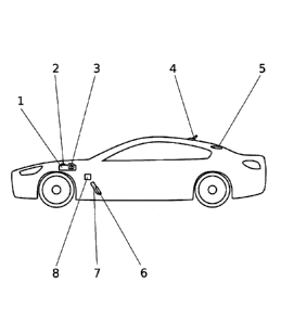
Figure 1: Schematic representation of the vehicle and the
reference numbers.
In this figure, the following reference numbers refer to:

CA 02915061 2015-12-10
-5-
1. Control unit
2. Signal receiver
3. Signal generator
4. GPS antenna
5. Third brake light
6. Brake pedal
7. Accelerator pedal encoder
8. Accelerator pedal
DESCRIPTION OF A PREFERRED EMBODIMENT
Hereinafter, a preferred embodiment of the invention, which is
only one of a variety of construction methods and which is
suitable for industrial realization, as well as an above-
described structure will be described.
A preferred embodiment of the arrangement according to the
invention for avoiding rear-end collisions can be realized
based on an electronic control unit (1) connected with the
electronic circuit of the vehicle and which is equipped with a
signal receiver (2) and a signal generator (3), and which is
programmed in a way that the following functions are carried
out in collaboration with the GPS antenna (4), the gas pedal
encoder (7) and the third brake light (5):
- when the vehicle is traveling on a highway or an expressway
at a speed lower than the minimum allowed speed, the control
unit (1) receives a signal from the GPS antenna (4), which is
forwarded to the signal generator (3) and activates the LEDs
of the third brake light (9) such that it blinks.
- 0.5 seconds before stepping on the brake pedal (6), the
accelerator pedal encoder (7) detects that the driver of the

CA 02915061 2015-12-10
. .
- 6 -
vehicle has retracted the foot abruptly (x pulses per second)
from the accelerator pedal (8) and sends a signal to the
control unit (1), such that the control unit (1) in turn sends
a signal to the third brake light (5) such that it blinks.
- if there is a sudden decrease in the vehicle speed even
without touching or actuating the brake (6), the control unit
(1) receives a signal from the electronic circuit of the
vehicle (multiplexing vehicle) or the ABS computer (in the
case of non-existent multiplexing) and signals the signal
generator (7) to send a signal to the third brake light (5)
such that it blinks.

Representative Drawing
A single figure which represents the drawing illustrating the invention.
Administrative Status

For a clearer understanding of the status of the application/patent presented on this page, the site Disclaimer , as well as the definitions for Patent , Administrative Status , Maintenance Fee  and Payment History  should be consulted.

Administrative Status

Title Date
Forecasted Issue Date 2021-09-21
(86) PCT Filing Date 2014-06-10
(87) PCT Publication Date 2014-12-18
(85) National Entry 2015-12-10
Examination Requested 2016-11-14
(45) Issued 2021-09-21

Abandonment History

Abandonment Date Reason Reinstatement Date
2018-06-11 FAILURE TO PAY APPLICATION MAINTENANCE FEE 2019-06-07

Maintenance Fee

Last Payment of $210.51 was received on 2023-06-02


 Upcoming maintenance fee amounts

Description Date Amount
Next Payment if small entity fee 2024-06-10 $125.00
Next Payment if standard fee 2024-06-10 $347.00

Note : If the full payment has not been received on or before the date indicated, a further fee may be required which may be one of the following

  • the reinstatement fee;
  • the late payment fee; or
  • additional fee to reverse deemed expiry.

Patent fees are adjusted on the 1st of January every year. The amounts above are the current amounts if received by December 31 of the current year.
Please refer to the CIPO Patent Fees web page to see all current fee amounts.

Payment History

Fee Type Anniversary Year Due Date Amount Paid Paid Date
Application Fee $400.00 2015-12-10
Maintenance Fee - Application - New Act 2 2016-06-10 $100.00 2016-05-10
Request for Examination $800.00 2016-11-14
Maintenance Fee - Application - New Act 3 2017-06-12 $100.00 2017-06-07
Reinstatement: Failure to Pay Application Maintenance Fees $200.00 2019-06-07
Maintenance Fee - Application - New Act 4 2018-06-11 $100.00 2019-06-07
Maintenance Fee - Application - New Act 5 2019-06-10 $200.00 2019-06-07
Maintenance Fee - Application - New Act 6 2020-06-10 $200.00 2020-06-05
Maintenance Fee - Application - New Act 7 2021-06-10 $204.00 2021-06-04
Final Fee 2021-07-26 $306.00 2021-07-21
Maintenance Fee - Patent - New Act 8 2022-06-10 $203.59 2022-07-15
Late Fee for failure to pay new-style Patent Maintenance Fee 2022-07-15 $150.00 2022-07-15
Maintenance Fee - Patent - New Act 9 2023-06-12 $210.51 2023-06-02
Owners on Record

Note: Records showing the ownership history in alphabetical order.

Current Owners on Record
PINO MENDEZ, JUAN JOSE
Past Owners on Record
None
Past Owners that do not appear in the "Owners on Record" listing will appear in other documentation within the application.
Documents

To view selected files, please enter reCAPTCHA code :


To view images, click a link in the Document Description column. To download the documents, select one or more checkboxes in the first column and then click the "Download Selected in PDF format (Zip Archive)" or the "Download Selected as Single PDF" button.

List of published and non-published patent-specific documents on the CPD .

If you have any difficulty accessing content, you can call the Client Service Centre at 1-866-997-1936 or send them an e-mail at CIPO Client Service Centre.


Document
Description 
Date
(yyyy-mm-dd) 
Number of pages   Size of Image (KB) 
Amendment 2019-11-22 5 144
Claims 2019-11-22 1 30
Examiner Requisition 2020-06-10 3 128
Amendment 2020-10-09 8 225
Claims 2020-10-09 1 30
Final Fee 2021-07-21 4 126
Representative Drawing 2021-08-23 1 5
Cover Page 2021-08-23 1 39
Electronic Grant Certificate 2021-09-21 1 2,527
Abstract 2015-12-10 1 74
Claims 2015-12-10 1 30
Drawings 2015-12-10 1 10
Description 2015-12-10 6 191
Representative Drawing 2015-12-10 1 9
Cover Page 2016-01-26 2 42
Examiner Requisition 2017-09-27 4 230
Amendment 2018-03-27 10 332
Claims 2018-03-27 1 28
Examiner Requisition 2019-06-27 3 179
International Search Report 2015-12-10 4 156
National Entry Request 2015-12-10 5 125
Request for Examination 2016-11-14 1 35