Sélection de la langue

Search

Sommaire du brevet 2915061 

Énoncé de désistement de responsabilité concernant l'information provenant de tiers

Une partie des informations de ce site Web a été fournie par des sources externes. Le gouvernement du Canada n'assume aucune responsabilité concernant la précision, l'actualité ou la fiabilité des informations fournies par les sources externes. Les utilisateurs qui désirent employer cette information devraient consulter directement la source des informations. Le contenu fourni par les sources externes n'est pas assujetti aux exigences sur les langues officielles, la protection des renseignements personnels et l'accessibilité.

Disponibilité de l'Abrégé et des Revendications

L'apparition de différences dans le texte et l'image des Revendications et de l'Abrégé dépend du moment auquel le document est publié. Les textes des Revendications et de l'Abrégé sont affichés :

  • lorsque la demande peut être examinée par le public;
  • lorsque le brevet est émis (délivrance).
(12) Brevet: (11) CA 2915061
(54) Titre français: DISPOSITIF POUR LA PREVENTION D'ACCIDENTS PAR COLLISION ARRIERE ET SON SYSTEME DE FONCTIONNEMENT
(54) Titre anglais: DEVICE FOR PREVENTING ACCIDENTS CAUSED BY REAR COLLISIONS AND OPERATING SYSTEM THEREOF
Statut: Octroyé
Données bibliographiques
(51) Classification internationale des brevets (CIB):
  • B60Q 1/44 (2006.01)
(72) Inventeurs :
  • PINO MENDEZ, JUAN JOSE (Espagne)
(73) Titulaires :
  • PINO MENDEZ, JUAN JOSE (Espagne)
(71) Demandeurs :
  • PINO MENDEZ, JUAN JOSE (Espagne)
(74) Agent: SMART & BIGGAR LP
(74) Co-agent:
(45) Délivré: 2021-09-21
(86) Date de dépôt PCT: 2014-06-10
(87) Mise à la disponibilité du public: 2014-12-18
Requête d'examen: 2016-11-14
Licence disponible: S.O.
(25) Langue des documents déposés: Anglais

Traité de coopération en matière de brevets (PCT): Oui
(86) Numéro de la demande PCT: PCT/ES2014/000093
(87) Numéro de publication internationale PCT: WO2014/198971
(85) Entrée nationale: 2015-12-10

(30) Données de priorité de la demande:
Numéro de la demande Pays / territoire Date
P201300843 Espagne 2013-06-10

Abrégés

Abrégé français

La présente invention concerne un dispositif constitué à partir d'une centrale électronique connectée au circuit électrique du véhicule, équipée d'un récepteur et d'un émetteur de signaux, qui met en oeuvre, en collaboration avec l'antenne GPS, le codeur de l'accélérateur, et la troisième lumière du frein, les fonctions suivantes: il active la troisième lumière du frein en la faisant clignoter, quand le véhicule circule sur une voie rapide ou sur l'autoroute à une vitesse inférieure à la vitesse minimale autorisée, 0,5 secondes avant d'appuyer sur la pédale de frein, le codeur de l'accélérateur active la troisième lumière de frein et s'il se produit une diminution brusque de la vitesse, il active également la troisième lumière de frein.


Abrégé anglais

The invention relates to a device for preventing accidents caused by rear-end collisions, comprising a an electronic control unit connected to the electronic circuit of the vehicle and provided with a signal receiver and transmitter. The electronic control unit performs the following functions together with the GPS antenna, the accelerator encoder and the third brake light, namely: Activation of the third brake light so that said light to flashes when the vehicle is travelling below the minimum speed limit on a dual-carriageway or motorway; activation of the third brake light by the accelerator encoder 0.5 seconds before the brake pedal is pressed; and activation of the third brake light in response to a sudden reduction in speed.

Revendications

Note : Les revendications sont présentées dans la langue officielle dans laquelle elles ont été soumises.


- 7 -
Claims
1. An arrangement for avoiding rear-end collisions and a
corresponding operating system formed by a control unit
connected with an electronic circuit of a vehicle comprising a
signal receiver and a signal generator and a GPS antenna, wherein
the following functions are performed in conjunction with an
accelerator pedal encoder and a third brake light:
- when the vehicle is traveling on a highway or an expressway
at a speed lower than the minimum posted speed, the control unit
receives a signal from the GPS antenna, which is forwarded to
the signal generator and activates the LEDs of the third brake
light such that it blinks;
- 0.5 seconds before stepping on the brake pedal, the accelerator
pedal encoder detects that the driver of the vehicle has
retracted the foot abruptly from the accelerator pedal and sends
a signal to the control unit, such that the control unit in turn
sends a signal to the third brake light such that it blinks;
- if there is a sudden decrease in a speed of the vehicle even
without touching or actuating the brake pedal, the control unit
receives a signal from the electronic circuit of the vehicle or
from an ABS computer of the vehicle, and signals the signal
generator to send a signal to the third brake light such that
it blinks.
Date Recue/Date Received 2020-10-09

Description

Note : Les descriptions sont présentées dans la langue officielle dans laquelle elles ont été soumises.

CA 02915061 2015-12-10
,
,
DEVICEFORPREVENTINGACCIDENTSCAUSEDBYREARCOLLISIONSAND
OPERTATINGSYSTEMTHEREOF
FIELD OF THE INVENTION
The present invention relates to an arrangement which by
blinking of the third brake light warns following vehicles
that there is a risk of collisions, wherein said signal is
issued temporarily based on three assumptions: Firstly, if the
preceding vehicle is preparing to brake, secondly, when the
preceding vehicle greatly reduced its speed and thirdly, if
the traffic flows with unusually low speed.
This invention solves the problem of rear-end collisions,
which are generated on roads and highways due to severe
braking, due to reduced speed or simply due to braking.
The arrangement according to the invention provides
significant advantages over prior art braking signal
arrangements, the most important being the simplicity of
construction and utilization of electrical and electronic
vehicle components.
Another important advantage is the use of the GPS system to
recognize the type of road on which the vehicle is traveling
in order to cause the control unit to activate the light
signal of the third brake light in the event of unusually slow
driving on highways and expressways.
BACKGROUND OF THE INVENTION
Currently there exists a system, with which some vehicles are
equipped, by means of which the emergency lighting is
activated when the ABS system comes into operation at a sudden

CA 02915061 2015-12-10
, .
. .
- 2 -
braking operation. Furthermore, the installation of high-
brightness LEDs in the brake lights is known, especially in
the third brake light, which are activated within a fraction
of a second before of a conventional bulb.
Although no invention was found that is identical with the
present invention, the documents retrieved representing the
prior art relating to the present invention are described
below.
Document ES 2 051 336 T3 relates to a vehicle deceleration
warning apparatus which comprises a piezoelectric sensor
device connected with the accelerator pedal or the bottom
plate for outputting a first signal when subjected to a
corresponding load; contact devices, which are connected with
each other or with the accelerator pedal or the bottom plate
for contacting the piezoelectric sensor upon release of the
accelerator pedal, to cause the sensor means to output a first
signal in response to the change of the load caused by the
contact means to the piezoelectric sensor device; and
switching means connected with the brake lights and to the
piezoelectric sensor means for analyzing said first signal
generated by the piezoelectric sensor means and for actuating
the brake lights in response to the analysis when the first
signal is above a predetermined threshold value. Although the
problem of the deceleration of the preceding vehicle is
solved, this is done very differently from the proposed
invention.
Document ES 2 138 898 Al describes an automatic system for
preventing accidents in every type of vehicle, which comprises
a circuit system connected with the electrical circuit of the
vehicle, comprising: at least one integrated circuit
comprising a device for detecting the safety distance or the

CA 029061 213112-10
- 3 -
distance between a vehicle and another preceding vehicle
and/or an obstacle lying ahead whose distance is related to
the speed of the vehicle, wherein commands are automatically
triggered in order to slow down and/or stop the vehicle to
avoid a collision, and means for temporarily switching off the
drive means. Even with its automatism, the problem is
certainly not solved with the reliability and simplicity as
with the proposed invention.
ES 1 066 558 U shall solve the problem by means of a recording
device that records images on a variety of cameras located in
the vehicle, a data microprocessor and a warning to the driver
of the vehicle in that the cameras record the presence and
position of an obstacle in front of or behind the vehicle and
send data on the presence and the position of the obstacle to
the microprocessor, which calculates the position and the
relative speed of the obstacle relative to the vehicle by
means of the data obtained by the camera, and emits a warning
to the driver in accordance with predetermined values of the
position and the relative approaching speed between the
obstacle and the vehicle and further enables protective
devices according to other predetermined values of the
position and the relative approaching speed between the
obstacle and the vehicle. The solution is very different to
that proposed by the present invention.
DESCRIPTION OF THE INVENTION
The arrangement according to the invention for avoiding
rear-end collisions is formed of an electronic control unit
which is connected with the electronic circuit of the vehicle,
and equipped with a signal receiver and a signal generator and
programmed in a way such that the following functions are

CA 029061 213112-10
. .
- 4 -
performed in conjunction with a GPS antenna (4), an
accelerator pedal encoder (7) and the third brake light (5):
- when the vehicle is traveling on a highway or an expressway
at a speed lower than the minimum allowed speed, the control
unit receives a signal from the GPS, which is forwarded to the
signal generator and activates the LEDs of the third brake
light such that it blinks.
- 0.5 seconds before stepping on the brake pedal, the
accelerator pedal encoder detects that the driver of the
vehicle has retracted the foot abruptly (x pulses per second)
from the accelerator pedal and sends a signal to the control
unit, such that the control unit in turn sends a signal to the
third brake light such that it blinks.
- if there is a sudden decrease in the vehicle speed even
without touching or actuating the brake, the control unit
receives a signal from the electronic circuit of the vehicle
(multiplexing vehicle) or the ABS computer (in the case of
non-existent multiplexing) and signals the signal generator to
send a signal to the third brake light (5) such that it
blinks.
BRIEF DESCRIPTION OF THE DRAWINGS
In the following, reference is made to a figure, which allows
to better understand the description of a particular and non-
limiting embodiment of the present invention.
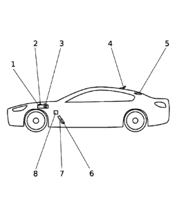
Figure 1: Schematic representation of the vehicle and the
reference numbers.
In this figure, the following reference numbers refer to:

CA 02915061 2015-12-10
-5-
1. Control unit
2. Signal receiver
3. Signal generator
4. GPS antenna
5. Third brake light
6. Brake pedal
7. Accelerator pedal encoder
8. Accelerator pedal
DESCRIPTION OF A PREFERRED EMBODIMENT
Hereinafter, a preferred embodiment of the invention, which is
only one of a variety of construction methods and which is
suitable for industrial realization, as well as an above-
described structure will be described.
A preferred embodiment of the arrangement according to the
invention for avoiding rear-end collisions can be realized
based on an electronic control unit (1) connected with the
electronic circuit of the vehicle and which is equipped with a
signal receiver (2) and a signal generator (3), and which is
programmed in a way that the following functions are carried
out in collaboration with the GPS antenna (4), the gas pedal
encoder (7) and the third brake light (5):
- when the vehicle is traveling on a highway or an expressway
at a speed lower than the minimum allowed speed, the control
unit (1) receives a signal from the GPS antenna (4), which is
forwarded to the signal generator (3) and activates the LEDs
of the third brake light (9) such that it blinks.
- 0.5 seconds before stepping on the brake pedal (6), the
accelerator pedal encoder (7) detects that the driver of the

CA 02915061 2015-12-10
. .
- 6 -
vehicle has retracted the foot abruptly (x pulses per second)
from the accelerator pedal (8) and sends a signal to the
control unit (1), such that the control unit (1) in turn sends
a signal to the third brake light (5) such that it blinks.
- if there is a sudden decrease in the vehicle speed even
without touching or actuating the brake (6), the control unit
(1) receives a signal from the electronic circuit of the
vehicle (multiplexing vehicle) or the ABS computer (in the
case of non-existent multiplexing) and signals the signal
generator (7) to send a signal to the third brake light (5)
such that it blinks.

Dessin représentatif
Une figure unique qui représente un dessin illustrant l'invention.
États administratifs

Pour une meilleure compréhension de l'état de la demande ou brevet qui figure sur cette page, la rubrique Mise en garde , et les descriptions de Brevet , États administratifs , Taxes périodiques et Historique des paiements devraient être consultées.

États administratifs

Titre Date
Date de délivrance prévu 2021-09-21
(86) Date de dépôt PCT 2014-06-10
(87) Date de publication PCT 2014-12-18
(85) Entrée nationale 2015-12-10
Requête d'examen 2016-11-14
(45) Délivré 2021-09-21

Historique d'abandonnement

Date d'abandonnement Raison Reinstatement Date
2018-06-11 Taxe périodique sur la demande impayée 2019-06-07

Taxes périodiques

Dernier paiement au montant de 210,51 $ a été reçu le 2023-06-02


 Montants des taxes pour le maintien en état à venir

Description Date Montant
Prochain paiement si taxe applicable aux petites entités 2024-06-10 125,00 $
Prochain paiement si taxe générale 2024-06-10 347,00 $

Avis : Si le paiement en totalité n'a pas été reçu au plus tard à la date indiquée, une taxe supplémentaire peut être imposée, soit une des taxes suivantes :

  • taxe de rétablissement ;
  • taxe pour paiement en souffrance ; ou
  • taxe additionnelle pour le renversement d'une péremption réputée.

Les taxes sur les brevets sont ajustées au 1er janvier de chaque année. Les montants ci-dessus sont les montants actuels s'ils sont reçus au plus tard le 31 décembre de l'année en cours.
Veuillez vous référer à la page web des taxes sur les brevets de l'OPIC pour voir tous les montants actuels des taxes.

Historique des paiements

Type de taxes Anniversaire Échéance Montant payé Date payée
Le dépôt d'une demande de brevet 400,00 $ 2015-12-10
Taxe de maintien en état - Demande - nouvelle loi 2 2016-06-10 100,00 $ 2016-05-10
Requête d'examen 800,00 $ 2016-11-14
Taxe de maintien en état - Demande - nouvelle loi 3 2017-06-12 100,00 $ 2017-06-07
Rétablissement: taxe de maintien en état non-payées pour la demande 200,00 $ 2019-06-07
Taxe de maintien en état - Demande - nouvelle loi 4 2018-06-11 100,00 $ 2019-06-07
Taxe de maintien en état - Demande - nouvelle loi 5 2019-06-10 200,00 $ 2019-06-07
Taxe de maintien en état - Demande - nouvelle loi 6 2020-06-10 200,00 $ 2020-06-05
Taxe de maintien en état - Demande - nouvelle loi 7 2021-06-10 204,00 $ 2021-06-04
Taxe finale 2021-07-26 306,00 $ 2021-07-21
Taxe de maintien en état - brevet - nouvelle loi 8 2022-06-10 203,59 $ 2022-07-15
Surtaxe pour omission de payer taxe de maintien en état - nouvelle Loi 2022-07-15 150,00 $ 2022-07-15
Taxe de maintien en état - brevet - nouvelle loi 9 2023-06-12 210,51 $ 2023-06-02
Titulaires au dossier

Les titulaires actuels et antérieures au dossier sont affichés en ordre alphabétique.

Titulaires actuels au dossier
PINO MENDEZ, JUAN JOSE
Titulaires antérieures au dossier
S.O.
Les propriétaires antérieurs qui ne figurent pas dans la liste des « Propriétaires au dossier » apparaîtront dans d'autres documents au dossier.
Documents

Pour visionner les fichiers sélectionnés, entrer le code reCAPTCHA :


Pour visualiser une image, cliquer sur un lien dans la colonne description du document. Pour télécharger l'image (les images), cliquer l'une ou plusieurs cases à cocher dans la première colonne et ensuite cliquer sur le bouton "Télécharger sélection en format PDF (archive Zip)" ou le bouton "Télécharger sélection (en un fichier PDF fusionné)".

Liste des documents de brevet publiés et non publiés sur la BDBC .

Si vous avez des difficultés à accéder au contenu, veuillez communiquer avec le Centre de services à la clientèle au 1-866-997-1936, ou envoyer un courriel au Centre de service à la clientèle de l'OPIC.


Description du
Document 
Date
(yyyy-mm-dd) 
Nombre de pages   Taille de l'image (Ko) 
Modification 2019-11-22 5 144
Revendications 2019-11-22 1 30
Demande d'examen 2020-06-10 3 128
Modification 2020-10-09 8 225
Revendications 2020-10-09 1 30
Taxe finale 2021-07-21 4 126
Dessins représentatifs 2021-08-23 1 5
Page couverture 2021-08-23 1 39
Certificat électronique d'octroi 2021-09-21 1 2 527
Abrégé 2015-12-10 1 74
Revendications 2015-12-10 1 30
Dessins 2015-12-10 1 10
Description 2015-12-10 6 191
Dessins représentatifs 2015-12-10 1 9
Page couverture 2016-01-26 2 42
Demande d'examen 2017-09-27 4 230
Modification 2018-03-27 10 332
Revendications 2018-03-27 1 28
Demande d'examen 2019-06-27 3 179
Rapport de recherche internationale 2015-12-10 4 156
Demande d'entrée en phase nationale 2015-12-10 5 125
Requête d'examen 2016-11-14 1 35